EP0872282A2 - Filterzentrifuge - Google Patents
Filterzentrifuge Download PDFInfo
- Publication number
- EP0872282A2 EP0872282A2 EP98105704A EP98105704A EP0872282A2 EP 0872282 A2 EP0872282 A2 EP 0872282A2 EP 98105704 A EP98105704 A EP 98105704A EP 98105704 A EP98105704 A EP 98105704A EP 0872282 A2 EP0872282 A2 EP 0872282A2
- Authority
- EP
- European Patent Office
- Prior art keywords
- centrifuge
- drum
- reflection
- axis
- ultrasonic sensor
- Prior art date
- Legal status (The legal status is an assumption and is not a legal conclusion. Google has not performed a legal analysis and makes no representation as to the accuracy of the status listed.)
- Granted
Links
Images


Classifications
-
- B—PERFORMING OPERATIONS; TRANSPORTING
- B04—CENTRIFUGAL APPARATUS OR MACHINES FOR CARRYING-OUT PHYSICAL OR CHEMICAL PROCESSES
- B04B—CENTRIFUGES
- B04B11/00—Feeding, charging, or discharging bowls
- B04B11/04—Periodical feeding or discharging; Control arrangements therefor
- B04B11/043—Load indication with or without control arrangements
-
- G—PHYSICS
- G01—MEASURING; TESTING
- G01F—MEASURING VOLUME, VOLUME FLOW, MASS FLOW OR LIQUID LEVEL; METERING BY VOLUME
- G01F23/00—Indicating or measuring liquid level or level of fluent solid material, e.g. indicating in terms of volume or indicating by means of an alarm
- G01F23/22—Indicating or measuring liquid level or level of fluent solid material, e.g. indicating in terms of volume or indicating by means of an alarm by measuring physical variables, other than linear dimensions, pressure or weight, dependent on the level to be measured, e.g. by difference of heat transfer of steam or water
- G01F23/28—Indicating or measuring liquid level or level of fluent solid material, e.g. indicating in terms of volume or indicating by means of an alarm by measuring physical variables, other than linear dimensions, pressure or weight, dependent on the level to be measured, e.g. by difference of heat transfer of steam or water by measuring the variations of parameters of electromagnetic or acoustic waves applied directly to the liquid or fluent solid material
- G01F23/296—Acoustic waves
- G01F23/2962—Measuring transit time of reflected waves
Definitions
- the invention relates to a device for measuring the fill level in a centrifuge drum according to the preamble of patent claim 1.
- Low frequency ultrasonic sensors used in hazardous areas Areas can be used, but require a minimum distance of 300mm. Furthermore, built-in components inside the Centrifuge space, such as with inverting filter centrifuges the spacer bolts between the drum cover and the moving floor are given, the sound reflections are destroyed.
- the invention is therefore based on the object in ultrasonic measuring devices of the type mentioned their applicability in determining the To improve the level in centrifuge drums, in particular dead spaces should be avoided, minimum distances between ultrasonic sensors and filling surface even with small drum diameters be created. In addition, interference from the centrifuge drum co-rotating centrifuge components avoided or be largely reduced.
- Reflecting surface Due to the deflection via a arranged inside the centrifuge drum Reflecting surface is the problem with ultrasonic sensors minimum distance to be met. According to the invention counts as Distance the sum of the distances between the filling surface and the reflecting surface on the one hand and between the reflecting surface and the ultrasonic sensor on the other hand.
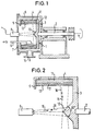
- FIG. 1 and 2 show a filter centrifuge with a filter drum 1, which consists of drum shaft 2, drum base 3, screen jacket 4 and drum rim 5 composed.
- the drum shaft 2 is the filter drum 1 enclosing centrifuge housing 6 stored.
- In the housing cover 7 are an ultrasonic sensor 8 and one inside the filter drum 1 projecting suspension filling pipe 9 is arranged.
- On the inside of the A reflective cone 10 is arranged on the drum base 3.
- the filter drum 1 is filled with a suspension, the solid components of which are in have settled in a solid layer or in a solid cake 11, Over which the liquid layer 12 consisting of filtrate with the Filling surface 13 is located.
- the filtrate penetrates in the operation of the Filter centrifuge the solid cake 11 and is 4 thrown out and through the outlet opening 14 of the centrifuge housing 6 derived.
- the solids of the remaining solid cake 11 can are discharged by a peeling device (not shown).
- FIG. 2 shows the sound signal 15 emitted by the ultrasonic sensor 8 (arrow with a solid line), which is deflected by 90 ° at the reflection cone 10.
- the sound signal 15 is reflected on the filling surface 13 and returns as an echo signal 16 (arrow with a broken line) to the ultrasonic sensor 8, where it is registered by its receiver unit.
- the distance between ultrasonic sensor 8 and filling surface is determined from the echo propagation time of sound signal 15 and echo signal 16, and the thickness of the filling layer is then determined.
- FIG. 3 shows a variant of the reflection cone 10a with a concave trained lateral surface. This tells them about the ultrasonic sensor 8 emitted sound signals 15 and those from the filling surface 13 reflected echo signals 16 a bundle, resulting in the receiver unit of the ultrasonic sensor 8 receive a stronger echo signal 16 can be.
- FIG. 4 shows a partial representation of the filter drum 101 of an inverting filter centrifuge, consisting of drum shaft 102, drum base 103, Sieve jacket 104, moving floor 105, sealing cover 106 and spacer bolts 107 composed.
- the cover 106 protrudes in a rotationally fixed manner Suspension filling pipe 109 in the inside of the filter drum 1 protruding end of the ultrasonic sensor 108 is arranged. That from the ultrasonic sensor 108 transmitted sound signal 115 is in the same way 1 and 2 radially fanned out as in the embodiment according to FIGS the inverting filter centrifuge at the drum peripheral speed rotating air column enclosed in the centrifuge drum he follows.
- the sound signal is not destroyed at the spacer bolts 107, but only experiences a slight weakening. Approx. 90% of the sound signal 115 pass freely between the spacer bolts 107 and generated a sufficiently strong one to evaluate the echo propagation time Echo signal 116.
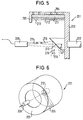
- FIG. 5 and 6 show in partial representation a filter drum 201, which is composed of drum shaft 202, drum base 203, screen jacket 204 and drum rim 205.
- a plane reflecting plate 210 On the inside of the drum base 203 in the center of a plane reflecting plate 210 is arranged, which includes the axis of rotation of the filter drum 201 at an angle of 45 o.
- the sound signal 215 emitted by the ultrasonic sensor 208 and the echo signal 216 reflected by the filling surface circulate with the filter drum 201, that is to say the sound signal 215 is only applied to a specific area of the filling surface 213, which affects this embodiment Particularly suitable for centrifuges that have components rotating in the centrifuge drum 201.
- the reflection plate can also be concave (not shown) be, whereby a bundling of sound and echo signal 215, 216 can be achieved.
- FIG. 7 shows a filter drum 301, which is composed of drum shaft 302, drum base 303, screen jacket 304 and drum rim 305.
- a reflecting surface 310 On the inside of the drum base 303 in the center of a reflecting surface 310 is disposed in a truncated cone shape of the lateral surface, which includes the axis of rotation of the filter drum 301 at an angle of 45 o.
- the ultrasonic sensor 308 is not arranged in alignment with the axis of rotation of the filter drum 301, but at a parallel distance therefrom, so that the sound signal 315 hits the reflection surface 310 and there by 90 ° to the filling surface 313 is redirected.
- the sound signal 315 always hits the filling surface 313 at one point with respect to the centrifuge housing (not shown).
- FIG. 8 shows a filter drum 401, which is composed of drum shaft 402, drum base 403, screen jacket 404 and drum rim 405.
- the drum shaft 402 is designed as a hollow shaft, through whose hollow channel the sound signal 415 emitted by the ultrasonic sensor 408 runs. This is deflected 90 ° to the filling surface 413 on a reflection surface 410 arranged on the housing wall of the centrifuge in alignment with the axis of rotation of the filter drum 401 and from there it returns as an echo signal 416 to the receiver part of the ultrasound sensor 408 which is stationary outside the centrifuge.
- the reflection surface on a the hollow channel opposite drum wall (not shown) arranged be.
- This configuration can be advantageous for centrifuge types where in certain operating phases, e.g. with an inverting filter centrifuge, the interior of the centrifuge drum is completely enclosed is.
- the arrangement of a hollow shaft can be advantageous for cases in which just an occasional check of the level inside Centrifuge drum is necessary, e.g. for setting the centrifuge control for a specific product.
- the ultrasonic sensor 408 is used only as needed, whereby, depending on the design, the ultrasonic pulse and the ultrasonic echo on a housing-fixed or on a drum-proof reflection surface.
Landscapes
- Physics & Mathematics (AREA)
- Acoustics & Sound (AREA)
- Electromagnetism (AREA)
- Thermal Sciences (AREA)
- Fluid Mechanics (AREA)
- General Physics & Mathematics (AREA)
- Centrifugal Separators (AREA)
- Measurement Of Levels Of Liquids Or Fluent Solid Materials (AREA)
Abstract
Description
- Fig. 1
- den Schnitt durch eine Filterzentrifuge,
- Fig. 2
- einen Teilausschnitt der Filterzentrifuge nach Fig. 1 mit ei nem geraden Reflexionskonus,
- Fig. 3
- einen Teilausschnitt nach Fig. 2 jedoch mit einem konkaven Reflexionskonus,
- Fig. 4
- einen Schnitt durch die Filtertrommel einer Stülpfilterzentrifuge,
- Fig. 5
- einen Teilausschnitt durch eine Filtertrommel mit einer ebenen Reflexionsfläche,
- Fig. 6
- die perspektivische Ansicht der Filtertrommel nach Fig. 5,
- Fig. 7
- den Schnitt durch eine Filtertrommel mit der Mantelfläche eines Kegelstumpfes als Reflexionsfläche und
- Fig. 8
- eine Filterzentrifuge mit einer Hohlwelle durch deren Hohlkanal die Ultraschallimpulse von außen in den Innenraum der Zentrifugentrommel gesendet werden.
Claims (15)
- Vorrichtung zur Messung der Füllstandshöhe in einer Zentrifugentrommel mittels eines Ultraschallsensors, dessen Ultraschallimpulse im wesentlichen senkrecht auf die Füllungsoberfläche der Zentrifugentrommel gerichtet sind, wobei über den aus der Echolaufzeit des Ultraschallimpulses ermittelbaren Abstand des Ultraschallsensors von der Füllungsoberfläche die Füllstandshöhe bestimmbar ist, dadurch gekennzeichnet, daß der Ultraschallimpuls über eine im Inneren der Zentrifugentrommel (1,101,201,301,401) angeordnete Reflexionsfläche (10,10a,110,210,310, 410) auf die Füllungsoberfläche (13,113,213,313,413) gerichtet wird.
- Vorrichtung nach Anspruch 1, dadurch gekennzeichnet, daß die Reflexionsfläche (10,10a) aus einem Reflexionskonus besteht, der am Trommelboden (3) der Zentrifugentrommel (1) angeordnet ist, wobei die Achse des Reflexionskonuses und die Strahlungsachse des Ultraschallsensors (8) mit der Rotationsachse der Zentrifugentrommel (1) fluchten.
- Vorrichtung nach Anspruch 2, dadurch gekennzeichnet, daß der Reflexionskonus (10) einen Konuswinkel von 90o einschließt.
- Vorrichtung nach Anspruch 2, dadurch gekennzeichnet, daß die Mantelfläche des Reflexionskonuses (10a) konkav ausgebildet ist.
- Vorrichtung nach Anspruch 1, dadurch gekennzeichnet, daß die Reflexionsfläche (310) die Mantelfläche eines Kegelstumpfes ist, der am Trommelboden (303) der Zentrifugentrommel (301) angeordnet ist, wobei die Achse des Kegelstumpfes mit der Rotationsachse der Zentrifugentrommel (301) fluchtet und die Strahlungsachse des Ultraschallsensors (308) im Parallelversatz zur Rotationsachse auf die Mantelfläche gerichtet ist.
- Vorrichtung nach Anspruch 5, dadurch gekennzeichnet, daß die Mantelfläche des Kegelstumpfes einen Kegelwinkel von 90o einschließt.
- Vorrichtung nach Anspruch 5, dadurch gekennzeichnet, daß die Mantelfläche des Kegelstumpfes konkav ausgebildet ist.
- Vorrichtung nach Anspruch 1, dadurch gekennzeichnet, daß die Reflexionsfläche aus einer ebenen Reflexionsplatte (210) besteht, die im Zentrum des Trommelbodens (203) der Zentrifugentrommel (201) angeordnet ist und mit der Rotationsachse der Zentrifugentrommel (201) einen Winkel von 45o einschließt, wobei die Strahlungsachse des Ultraschallsensors (208) mit der Rotationsachse fluchtet.
- Vorrichtung nach Anspruch 8, dadurch gekennzeichnet, daß die Reflexionsfläche aus einer konkaven Reflexionsplatte (210) besteht.
- Vorrichtung nach einem der Ansprüche 1 bis 9, dadurch gekennzeichnet, daß der Ultraschallsensor (8,208,308) in der dem Trommelboden (3,203,303) der Zentrifugentrommel (1,201,301) gegenüberliegenden Wandung des Zentrifugengehäuses angeordnet ist.
- Vorrichtung nach Anspruch 10, dadurch gekennzeichnet, daß der Ultraschallsensor in der Gehäusetür des Zentrifugengehäuses angeordnet ist.
- Vorrichtung nach einem der Ansprüche 1 bis 9, dadurch gekennzeichnet, daß bei einer Zentrifuge mit allseits umschlossenen Zentrifugeninnenraum der Ultraschallsensor (108) an dem drehfest in den Zentrifugeninnenraum ragenden Ende des Füllrohres (109) angeordnet ist.
- Vorrichtung nach Anspruch 1, dadurch gekennzeichnet, daß die Welle der Zentrifugentrommel (401) eine Hohlwelle (402) ist, durch deren Hohlkanal der Ultraschallimpuls von dem außerhalb der Hohlwelle (402) stationär angeordneten Ultraschallsensor (408) in die im Inneren der Zentrifugentrommel (401) angeordnete Reflexionsfläche gerichtet ist.
- Vorrichtung nach Anspruch 13, dadurch gekennzeichnet, daß die Reflexionsfläche auf der der Hohlwelle gegenüberliegenden Wandung der Zentrifugentrommel (401) angeordnet ist.
- Vorrichtung nach Anspruch 13, dadurch gekennzeichnet, daß die Reflexionsfläche (410) auf der der Hohlwelle gegenüberliegenden Wandung des Zentrifugengehäuses angeordnet ist.
Applications Claiming Priority (2)
| Application Number | Priority Date | Filing Date | Title |
|---|---|---|---|
| DE19716129 | 1997-04-17 | ||
| DE19716129A DE19716129C1 (de) | 1997-04-17 | 1997-04-17 | Filterzentrifuge |
Publications (3)
| Publication Number | Publication Date |
|---|---|
| EP0872282A2 true EP0872282A2 (de) | 1998-10-21 |
| EP0872282A3 EP0872282A3 (de) | 1999-09-01 |
| EP0872282B1 EP0872282B1 (de) | 2002-02-27 |
Family
ID=7826834
Family Applications (1)
| Application Number | Title | Priority Date | Filing Date |
|---|---|---|---|
| EP98105704A Expired - Lifetime EP0872282B1 (de) | 1997-04-17 | 1998-03-28 | Filterzentrifuge |
Country Status (2)
| Country | Link |
|---|---|
| EP (1) | EP0872282B1 (de) |
| DE (2) | DE19716129C1 (de) |
Cited By (2)
| Publication number | Priority date | Publication date | Assignee | Title |
|---|---|---|---|---|
| CN106334631A (zh) * | 2016-09-30 | 2017-01-18 | 江苏牡丹离心机制造有限公司 | 一种带反应槽的过滤离心机 |
| KR20170134391A (ko) * | 2015-04-08 | 2017-12-06 | 만 운트 훔멜 게엠베하 | 원심분리기 |
Families Citing this family (1)
| Publication number | Priority date | Publication date | Assignee | Title |
|---|---|---|---|---|
| DE19919118C2 (de) * | 1999-04-27 | 2003-02-27 | Krauss Maffei Process Technolo | Verfahren zur Messung der Füllstandshöhe in einer Zentrifugentrommel einer Filterzentrifuge und Vorrichtung zur Durchführung des Verfahrens |
Family Cites Families (2)
| Publication number | Priority date | Publication date | Assignee | Title |
|---|---|---|---|---|
| DE3020211A1 (de) * | 1980-05-28 | 1981-12-03 | Krauss-Maffei AG, 8000 München | Verfahren zum entwaessern von in suspensionen enthaltenen farbstoffen |
| DE4414602A1 (de) * | 1994-04-27 | 1995-11-02 | Pfeifer & Langen | Verfahren zur Steuerung des Nutzungsgrades einer diskontinuierlich arbeitenden Zentrifuge, insbesondere einer Zuckerzentrifuge |
-
1997
- 1997-04-17 DE DE19716129A patent/DE19716129C1/de not_active Expired - Fee Related
-
1998
- 1998-03-28 EP EP98105704A patent/EP0872282B1/de not_active Expired - Lifetime
- 1998-03-28 DE DE59803162T patent/DE59803162D1/de not_active Expired - Lifetime
Cited By (5)
| Publication number | Priority date | Publication date | Assignee | Title |
|---|---|---|---|---|
| KR20170134391A (ko) * | 2015-04-08 | 2017-12-06 | 만 운트 훔멜 게엠베하 | 원심분리기 |
| US10357788B2 (en) | 2015-04-08 | 2019-07-23 | Mann+Hummel Gmbh | Centrifugal separator having a self-powered service readiness indicator |
| KR102483005B1 (ko) | 2015-04-08 | 2022-12-29 | 만 운트 훔멜 게엠베하 | 원심분리기 |
| DE112015006428B4 (de) * | 2015-04-08 | 2025-05-28 | Mann+Hummel Gmbh | Zentrifugalseparator |
| CN106334631A (zh) * | 2016-09-30 | 2017-01-18 | 江苏牡丹离心机制造有限公司 | 一种带反应槽的过滤离心机 |
Also Published As
| Publication number | Publication date |
|---|---|
| EP0872282A3 (de) | 1999-09-01 |
| EP0872282B1 (de) | 2002-02-27 |
| DE19716129C1 (de) | 1998-10-15 |
| DE59803162D1 (de) | 2002-04-04 |
Similar Documents
| Publication | Publication Date | Title |
|---|---|---|
| DE2713921C2 (de) | Vorrichtung zum Messen der radialen Abmessungen eines Rohres mittels Ultraschall | |
| DE3812293C2 (de) | ||
| EP0903563B1 (de) | Vorrichtung zur Feststellung und/oder Überwachung eines vorbestimmten Füllstands in einem Behälter | |
| DE3633047C2 (de) | ||
| EP0766070B1 (de) | Ultraschallwandler | |
| DE3016323C3 (de) | Gerät zur akustischen Messung der Dichte einer Flüssigkeit | |
| EP2440888B1 (de) | Verfahren zum messen einer messgrösse | |
| DE4419462C2 (de) | Berührungsloser Füllstandsmesser | |
| DE102008029772A1 (de) | Verfahren und Messsystem zur Bestimmung und/oder Überwachung des Durchflusses eines Messmediums durch ein Messrohr | |
| EP1480023B1 (de) | Messgerät mit Vorrichtung zur Erkennung des angeschlossenenen Ultraschallsensors | |
| DE4306193B4 (de) | Füllstandssensor | |
| DE19839942A1 (de) | Einparkhilfe für ein Kraftfahrzeug | |
| EP3343185B1 (de) | Ultraschalldurchflussmessgerät und verfahren zur messung des durchflusses | |
| EP0872282B1 (de) | Filterzentrifuge | |
| EP1344052B1 (de) | Verfahren und rollenprüfkopf zur ultraschallprüfung von überlappschweissnaehten zwischen blechen nach dem impulsverfahren | |
| DE4011923A1 (de) | Verfahren zur detektion von phasengrenzflaechen oder schichtungen von unterschiedlichen nicht mischbaren und sich durch schwerkraftseparation trennenden fluessigkeiten | |
| EP0138017B1 (de) | Verfahren zur Ultraschall-Durchflussmessung nach dem Dopplerprinzip mit verbesserter Ortsauflösung | |
| DE19516789B4 (de) | Blutreservoirfüllstand-Überwachungsvorrichtung | |
| DE10356114A1 (de) | Vorrichtung zur Bestimmung und/oder Überwachung des Volumen- und/oder Massendurchflusses eines Messmediums | |
| DE10350084A1 (de) | Sensoreinrichtung zum Erfassen eines Füllstands und Verfahren zum Betreiben der Sensoreinrichtung | |
| DE2653864C3 (de) | Verfahren zur Bestimmung des Endpunktes eines Prozesses sowie Meßeinrichtung für die Durchführung eines solchen Verfahrens | |
| DE102023113539A1 (de) | Ultraschall-Durchflussmessvorrichtung zum Bestimmen eines Durchflusses eines fluiden Mediums durch eine Rohrleitung | |
| DE2950237C2 (de) | Vorrichtung zum Prüfen von Punktschweißungen an Rädern | |
| DE4437684C2 (de) | Vorrichtung zur Messung der Konzentration einer in einem Behältnis befindlichen, sich zeitlich stofflich verändernden Flüssigkeit | |
| EP1063016B1 (de) | Verfahren und Vorrichtung zur Messung der Füllstandshöhe in einer Filterzentrifuge |
Legal Events
| Date | Code | Title | Description |
|---|---|---|---|
| PUAI | Public reference made under article 153(3) epc to a published international application that has entered the european phase |
Free format text: ORIGINAL CODE: 0009012 |
|
| AK | Designated contracting states |
Kind code of ref document: A2 Designated state(s): CH DE GB IE IT LI |
|
| AX | Request for extension of the european patent |
Free format text: AL;LT;LV;MK;RO;SI |
|
| PUAL | Search report despatched |
Free format text: ORIGINAL CODE: 0009013 |
|
| AK | Designated contracting states |
Kind code of ref document: A3 Designated state(s): AT BE CH DE DK ES FI FR GB GR IE IT LI LU MC NL PT SE |
|
| AX | Request for extension of the european patent |
Free format text: AL;LT;LV;MK;RO;SI |
|
| RAP1 | Party data changed (applicant data changed or rights of an application transferred) |
Owner name: MANNESMANN DEMAG KRAUSS-MAFFEI AG |
|
| 17P | Request for examination filed |
Effective date: 20000301 |
|
| AKX | Designation fees paid |
Free format text: CH DE GB IE IT LI |
|
| GRAG | Despatch of communication of intention to grant |
Free format text: ORIGINAL CODE: EPIDOS AGRA |
|
| GRAG | Despatch of communication of intention to grant |
Free format text: ORIGINAL CODE: EPIDOS AGRA |
|
| GRAH | Despatch of communication of intention to grant a patent |
Free format text: ORIGINAL CODE: EPIDOS IGRA |
|
| 17Q | First examination report despatched |
Effective date: 20010711 |
|
| GRAH | Despatch of communication of intention to grant a patent |
Free format text: ORIGINAL CODE: EPIDOS IGRA |
|
| REG | Reference to a national code |
Ref country code: GB Ref legal event code: IF02 |
|
| GRAA | (expected) grant |
Free format text: ORIGINAL CODE: 0009210 |
|
| RAP1 | Party data changed (applicant data changed or rights of an application transferred) |
Owner name: KRAUSS-MAFFEI PROCESS TECHNOLOGY AG |
|
| AK | Designated contracting states |
Kind code of ref document: B1 Designated state(s): CH DE GB IE IT LI |
|
| REG | Reference to a national code |
Ref country code: CH Ref legal event code: EP |
|
| GBT | Gb: translation of ep patent filed (gb section 77(6)(a)/1977) |
Effective date: 20020227 |
|
| REF | Corresponds to: |
Ref document number: 59803162 Country of ref document: DE Date of ref document: 20020404 |
|
| REG | Reference to a national code |
Ref country code: CH Ref legal event code: NV Representative=s name: KIRKER & CIE SA |
|
| PLBE | No opposition filed within time limit |
Free format text: ORIGINAL CODE: 0009261 |
|
| STAA | Information on the status of an ep patent application or granted ep patent |
Free format text: STATUS: NO OPPOSITION FILED WITHIN TIME LIMIT |
|
| 26N | No opposition filed |
Effective date: 20021128 |
|
| PG25 | Lapsed in a contracting state [announced via postgrant information from national office to epo] |
Ref country code: DE Free format text: LAPSE BECAUSE OF NON-PAYMENT OF DUE FEES Effective date: 20111001 |
|
| PGFP | Annual fee paid to national office [announced via postgrant information from national office to epo] |
Ref country code: IE Payment date: 20130315 Year of fee payment: 16 |
|
| REG | Reference to a national code |
Ref country code: IE Ref legal event code: MM4A |
|
| PG25 | Lapsed in a contracting state [announced via postgrant information from national office to epo] |
Ref country code: IE Free format text: LAPSE BECAUSE OF NON-PAYMENT OF DUE FEES Effective date: 20140328 |
|
| PGFP | Annual fee paid to national office [announced via postgrant information from national office to epo] |
Ref country code: GB Payment date: 20150324 Year of fee payment: 18 |
|
| GBPC | Gb: european patent ceased through non-payment of renewal fee |
Effective date: 20160328 |
|
| PG25 | Lapsed in a contracting state [announced via postgrant information from national office to epo] |
Ref country code: GB Free format text: LAPSE BECAUSE OF NON-PAYMENT OF DUE FEES Effective date: 20160328 |
|
| PGFP | Annual fee paid to national office [announced via postgrant information from national office to epo] |
Ref country code: CH Payment date: 20170327 Year of fee payment: 20 |
|
| PGFP | Annual fee paid to national office [announced via postgrant information from national office to epo] |
Ref country code: DE Payment date: 20170525 Year of fee payment: 20 |
|
| PGFP | Annual fee paid to national office [announced via postgrant information from national office to epo] |
Ref country code: IT Payment date: 20170323 Year of fee payment: 20 |
|
| REG | Reference to a national code |
Ref country code: DE Ref legal event code: R071 Ref document number: 59803162 Country of ref document: DE |
|
| REG | Reference to a national code |
Ref country code: CH Ref legal event code: PL |