EP0872322A2 - Procédé et dispositif pour traiter des déchets à base de matières plastiques - Google Patents
Procédé et dispositif pour traiter des déchets à base de matières plastiques Download PDFInfo
- Publication number
- EP0872322A2 EP0872322A2 EP98106868A EP98106868A EP0872322A2 EP 0872322 A2 EP0872322 A2 EP 0872322A2 EP 98106868 A EP98106868 A EP 98106868A EP 98106868 A EP98106868 A EP 98106868A EP 0872322 A2 EP0872322 A2 EP 0872322A2
- Authority
- EP
- European Patent Office
- Prior art keywords
- grinding
- waste
- storage space
- products
- air
- Prior art date
- Legal status (The legal status is an assumption and is not a legal conclusion. Google has not performed a legal analysis and makes no representation as to the accuracy of the status listed.)
- Granted
Links
Images


Classifications
-
- B—PERFORMING OPERATIONS; TRANSPORTING
- B29—WORKING OF PLASTICS; WORKING OF SUBSTANCES IN A PLASTIC STATE IN GENERAL
- B29B—PREPARATION OR PRETREATMENT OF THE MATERIAL TO BE SHAPED; MAKING GRANULES OR PREFORMS; RECOVERY OF PLASTICS OR OTHER CONSTITUENTS OF WASTE MATERIAL CONTAINING PLASTICS
- B29B17/00—Recovery of plastics or other constituents of waste material containing plastics
- B29B17/04—Disintegrating plastics, e.g. by milling
- B29B17/0404—Disintegrating plastics, e.g. by milling to powder
-
- B—PERFORMING OPERATIONS; TRANSPORTING
- B02—CRUSHING, PULVERISING, OR DISINTEGRATING; PREPARATORY TREATMENT OF GRAIN FOR MILLING
- B02C—CRUSHING, PULVERISING, OR DISINTEGRATING IN GENERAL; MILLING GRAIN
- B02C13/00—Disintegrating by mills having rotary beater elements ; Hammer mills
- B02C13/14—Disintegrating by mills having rotary beater elements ; Hammer mills with vertical rotor shaft, e.g. combined with sifting devices
-
- B—PERFORMING OPERATIONS; TRANSPORTING
- B29—WORKING OF PLASTICS; WORKING OF SUBSTANCES IN A PLASTIC STATE IN GENERAL
- B29B—PREPARATION OR PRETREATMENT OF THE MATERIAL TO BE SHAPED; MAKING GRANULES OR PREFORMS; RECOVERY OF PLASTICS OR OTHER CONSTITUENTS OF WASTE MATERIAL CONTAINING PLASTICS
- B29B17/00—Recovery of plastics or other constituents of waste material containing plastics
- B29B17/02—Separating plastics from other materials
-
- B—PERFORMING OPERATIONS; TRANSPORTING
- B02—CRUSHING, PULVERISING, OR DISINTEGRATING; PREPARATORY TREATMENT OF GRAIN FOR MILLING
- B02C—CRUSHING, PULVERISING, OR DISINTEGRATING IN GENERAL; MILLING GRAIN
- B02C13/00—Disintegrating by mills having rotary beater elements ; Hammer mills
- B02C13/14—Disintegrating by mills having rotary beater elements ; Hammer mills with vertical rotor shaft, e.g. combined with sifting devices
- B02C2013/145—Disintegrating by mills having rotary beater elements ; Hammer mills with vertical rotor shaft, e.g. combined with sifting devices with fast rotating vanes generating vortexes effecting material on material impact
-
- B—PERFORMING OPERATIONS; TRANSPORTING
- B29—WORKING OF PLASTICS; WORKING OF SUBSTANCES IN A PLASTIC STATE IN GENERAL
- B29B—PREPARATION OR PRETREATMENT OF THE MATERIAL TO BE SHAPED; MAKING GRANULES OR PREFORMS; RECOVERY OF PLASTICS OR OTHER CONSTITUENTS OF WASTE MATERIAL CONTAINING PLASTICS
- B29B17/00—Recovery of plastics or other constituents of waste material containing plastics
- B29B17/02—Separating plastics from other materials
- B29B2017/0213—Specific separating techniques
- B29B2017/0217—Mechanical separating techniques; devices therefor
- B29B2017/0224—Screens, sieves
-
- B—PERFORMING OPERATIONS; TRANSPORTING
- B29—WORKING OF PLASTICS; WORKING OF SUBSTANCES IN A PLASTIC STATE IN GENERAL
- B29B—PREPARATION OR PRETREATMENT OF THE MATERIAL TO BE SHAPED; MAKING GRANULES OR PREFORMS; RECOVERY OF PLASTICS OR OTHER CONSTITUENTS OF WASTE MATERIAL CONTAINING PLASTICS
- B29B17/00—Recovery of plastics or other constituents of waste material containing plastics
- B29B17/04—Disintegrating plastics, e.g. by milling
- B29B2017/0424—Specific disintegrating techniques; devices therefor
- B29B2017/0492—Projecting the material on stationary or moving impact surfaces or plates
-
- B—PERFORMING OPERATIONS; TRANSPORTING
- B29—WORKING OF PLASTICS; WORKING OF SUBSTANCES IN A PLASTIC STATE IN GENERAL
- B29L—INDEXING SCHEME ASSOCIATED WITH SUBCLASS B29C, RELATING TO PARTICULAR ARTICLES
- B29L2009/00—Layered products
- B29L2009/003—Layered products comprising a metal layer
-
- Y—GENERAL TAGGING OF NEW TECHNOLOGICAL DEVELOPMENTS; GENERAL TAGGING OF CROSS-SECTIONAL TECHNOLOGIES SPANNING OVER SEVERAL SECTIONS OF THE IPC; TECHNICAL SUBJECTS COVERED BY FORMER USPC CROSS-REFERENCE ART COLLECTIONS [XRACs] AND DIGESTS
- Y02—TECHNOLOGIES OR APPLICATIONS FOR MITIGATION OR ADAPTATION AGAINST CLIMATE CHANGE
- Y02W—CLIMATE CHANGE MITIGATION TECHNOLOGIES RELATED TO WASTEWATER TREATMENT OR WASTE MANAGEMENT
- Y02W30/00—Technologies for solid waste management
- Y02W30/50—Reuse, recycling or recovery technologies
- Y02W30/52—Mechanical processing of waste for the recovery of materials, e.g. crushing, shredding, separation or disassembly
-
- Y—GENERAL TAGGING OF NEW TECHNOLOGICAL DEVELOPMENTS; GENERAL TAGGING OF CROSS-SECTIONAL TECHNOLOGIES SPANNING OVER SEVERAL SECTIONS OF THE IPC; TECHNICAL SUBJECTS COVERED BY FORMER USPC CROSS-REFERENCE ART COLLECTIONS [XRACs] AND DIGESTS
- Y02—TECHNOLOGIES OR APPLICATIONS FOR MITIGATION OR ADAPTATION AGAINST CLIMATE CHANGE
- Y02W—CLIMATE CHANGE MITIGATION TECHNOLOGIES RELATED TO WASTEWATER TREATMENT OR WASTE MANAGEMENT
- Y02W30/00—Technologies for solid waste management
- Y02W30/50—Reuse, recycling or recovery technologies
- Y02W30/62—Plastics recycling; Rubber recycling
Definitions
- the invention relates to a method for processing Waste products based on plastics, Containing plastic composite materials, rejects Plastics, cellulose, light materials such as paper, cardboard, Light foams as well as metal waste and dirt particles as well as moisture, for the purpose of recovering recyclable and processable materials, especially plastic and optionally cellulose, in which the waste products by Removing the metal waste and dirt particles cleaned and to be crushed into a coarse raw meal and that Finely chopped raw material into a pourable waste material and is dried, the fine grinding at simultaneous separation of the composite materials in one Impact vortex mill with grinding air generating more energy Turbulence vortex takes place, which generates frictional heat and the moisture introduced into the evaporation products with the raw material is transferred and the grinding air and the raw material about one Inlet introduced into a grinding chamber and out through an outlet the grinding air, the finely divided waste and the the evaporation products are removed.
- the invention relates to a system for Carrying out the process for the preparation of Waste products based on plastic, Plastic composite materials and rejects including Cellulose, light materials, metal waste, dirt particles and Moisture
- a system for Carrying out the process for the preparation of Waste products based on plastic, Plastic composite materials and rejects including Cellulose, light materials, metal waste, dirt particles and Moisture comprising at least a first device for Pre-shredding the waste products into a raw material and where appropriate, facilities for cleaning and separating and Separate for those in waste products except plastics contained different materials and another Device for finely crushing the raw material in shape an impact vortex mill with a grinding chamber with an inlet for Grinding air and raw material and an outlet for grinding air and finely shredded waste.
- plastics for thermal processing required the plastic waste of dirt particles, Clean all types of impurities. Required here especially the removal of water and moisture as well as from Cellulose particles in the broadest sense from composite materials, Paper etc. as well as light foam particles, in particular Polystyrene particles, a lot of effort.
- Processes and plants for processing plastic waste are both the dirt particles and heavy particles as the cellulose and lightweight particles are also predominantly wet or sorted out floating with the help of water and severed. This requires a lot of water required, in particular the complete removal of Cellulose particles cause difficulties.
- shredders For shredding plastic waste Usually in a first stage for pre-shredding so-called shredders used, while for the Very fine crushing impact vortex mills can be used.
- Impact vortex mills for the fine grinding of Pre-shredded plastic waste is made, for example DE 35 43 370 A1 or the German utility models DE 295 15 434 U1 or DE 295 15 433 U1 known.
- the crushing principle of the impact vortex mill is based on one high air throughput, whereby the grinding air through the rotating and the fixed parts of the mill and a suitable one Air flow is placed in a considerable turbulence. This in the grinding air metered-in material to be ground becomes one Large number of rapidly repeated impact effects, shear effects and / or subjected to frictional effects and finely crushed.
- the invention has for its object an economic Process and a plant therefor for the preparation of Waste products based on plastics, light materials and To create cellulose that ends up being a materially clean pourable separated from all other materials Plastic powder is obtained that is dry and one low residual moisture, based on the plastic, and thus in the case of thermoplastic waste thermal recovery immediately, for example Extrusion, is feedable.
- the grinding air inside the Grinding chamber of the impact vortex mill used for the Very fine comminution of the raw material in the direction of the outlet suck off the impact vortex mill and the grinding air together with the evaporation products and that in the individual materials separated and finely comminuted waste from the Grinding room transferred into a storage space under pressure increase and in the storage space the evaporation products separated and together with the grinding air from the storage space be carried away and the individual materials of the separated, finely shredded waste in the storage space falling under the influence of gravity and from the Evaporation products liberate from the dry Storage space to be carried out.
- evaporation products is here also understood the moisture contained in the grinding air.
- the inventive method is characterized in that as a raw material only a pre-crushed and from Dirt particles and metal particles cleaned Waste product based on plastics and Plastic composite materials and / or rejects used that is still cellulose particles and also Lightweight particles, such as light foams, for example Polystyrene.
- cellulose particles are in the sense the invention understood paper, pulp, cardboard, etc., the as pollution or in combination with Plastic composite materials are included in the waste product.
- Rejects are waste from the paper industry predominantly contain cellulose and difficult to utilize are like waste paper, sections, laminated paper waste, Packaging waste, often with metal clips, Aluminum foil or plastic foil occur in the composite.
- the method according to the invention as residual material recycled plastic with a residual moisture of less than 1 % By weight, preferably less than 0.5% by weight, preferably less than 0.4% by weight based on the weight of the Plastic. This is essential of economic importance, for example plastic only thermoplastic processing such as extrusion if there is a residual moisture below 0.6% by weight contains.
- the temperature of the the grinding air leaving the grinding chamber in the direction of the storage space measure and depending on the measured temperature of the Grinding air for additional water in the grinding room Evaporation to lower the temperature of the grinding air introduce.
- This is when processing plastic and plastic waste introduced additional water to the Grinding air temperature at the measuring point in a range from 8 to 30 ° C below the boiling point of water at atmospheric pressure to keep, so at about 70 to 92 ° C.
- This is preferred additional water discontinuously at intervals or intermittently introduced into the grinding chamber, for example in the Injected air flow.
- the throughput of the raw material through the Mill can be increased if the dwell time is too short dimensioned, the raw material remains too moist, because not enough moisture is thrown out and evaporate can.
- preference is given to at least 1 bar, preferably about 2 bar higher pressure than within the Maintaining the grinding chamber pressure.
- the inventive method can be used for both Processing waste with up to 90% by weight Share of plastic waste as well as up to 70-80% by weight Proportion of cellulosic materials and only small proportions applied to plastic.
- the comminution of the raw material is proposed Impact vortex mill between the inlet area and the grinding chamber with a fan and between the grinding chamber and outlet area to equip with another fan, the Delivery capacity of the fan in the exit area is greater than that of the fan in the inlet area, so that a suction is generated in the direction of the outlet area in the grinding chamber and in the storage space above the inside of the grinding chamber Impact vortex mill lying pressure can be generated.
- the transportation of the raw material within the Impact vortex mill in one direction from inlet to outlet slow floating in the grinding air flow with an air suction ensured.
- the cellular wheel sluice is included connected to the pressure line of a pneumatic conveyor system and consists of a slow around a horizontal axis rotating cell wheel into which the solid particles from the Fall in silo and from the cell wheel evenly into the Pressure line are promoted.
- the cellular wheel takes over at the same time the seal between the silo and the Pressure line.
- the exhaust line for the grinding air including the vaporization products from the storage space be provided with a flap or the like, the Opening cross section is adjustable, so that here too the pressure in the storage space can be regulated accordingly.
- a temperature measuring device To the temperature of the emerging from the impact vortex mill Measuring grinding air is a temperature measuring device in the Area of the connecting line for the grinding air between the Outlet of the impact vortex mill and the storage space provided.
- the supply of additional water to the grinding chamber provided with the grinding air For influencing the temperature of the grinding air prefers the supply of additional water to the grinding chamber provided with the grinding air.
- a facility for Injecting water into the grinding chamber can, for example, in the The area where the grinding air is fed into the grinding chamber, i.e. to the impact vortex mill be arranged.
- the device for Injecting water to be introduced into the grinding chamber in relation to the quantity and the time dependence depending from that measured by means of the temperature measuring device
- the temperature of the grinding air when leaving the impact vortex mill increases Taxes.
- the system according to the invention can be used both for processing of mostly dry waste products as well as very wet and dirty waste products are used. If the system is used exclusively for the processing of predominantly dry waste products are to be used, a structure according to the characteristic features of the Claim 19 proposed.
- the impact reactor according to the invention is robust and simple built up by having a single wave that by means of a drive can be driven and both Fans as well as the grinding room and grinding stages forming parts are attached.
- the air suction between the entrance and output of the grinding chamber is through the two fans in the order of magnitude through appropriate training of the Fans with their blades - size, number - fixed set. So there is always a minimum air suction ensured. An additional regulation of the two Fans depending on each other is not required.
- Another control is carried out by the Impact vortex mill and the upper fan downstream Storage space, for example a silo, which creates a counter pressure. According to the counter pressure in the storage space is controlled so that no more grinding air is let out, as by the fan in the entrance area of the impact vortex mill is drawn in.
- the connecting line between the impact reactor and Storage space, in particular silo, preferably has at the outlet of the Impact reactor on a diffuser.
- a particularly high level of turbulence and eddy is created with the Formation of a profile on the inside of the drum the characterizing features of claim 17 achieved.
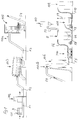
- Material feed device 101 for in compact form such as Bale B, delivered waste products.
- Waste products here are, for example, waste films made of thermoplastic Agricultural plastic or plastic bottles and Thermoplastic containers which Contain dirt particles, cellulose particles, paper and optionally also lightweight foam particles, such as styrofoam, Scrap metal or the like.
- the bales B are over a Conveyor F1, for example conveyor belt, one Bale solver 102 fed and from here the cut Bales by means of a further conveying device F2, for example conveyor belt, a device 103 for Material pre-cleaning, for example a sieve drum.
- the Scattered bale material is then added by means of another Conveyor F3, for example conveyor belt, one Precrushing device 105, for example one Shredder fed.
- one Precrushing device 105 for example one Shredder fed.
- Metal separator 104a for separating Metal parts (Fe) can be provided.
- Facilities such as Material feed 101, bale cutter 102, sieve drum 103, Metal separators 104a and shredders 105 are known.
- the waste product pre-shredded in the shredder 105 becomes via a further conveyor F4, for example a Conveyor belt or a pneumatic conveyor, one Reservoir 106 abandoned.
- a further conveyor F4 for example a Conveyor belt or a pneumatic conveyor
- the Storage container 106 can be another device for Metal deposition 104b - non-ferrous metals - on the delivery line F4 be arranged to deposit remaining metal parts. It both FE and non-ferrous metals from the waste material removed by means of the metal separator.
- the storage container 106 is then the result of pre-shredding, cleaning and metal separation obtained raw material, which now only the composite materials, plastic, cellulose and others Contains lightweight particles.
- This raw grist will then the impact reactor 200 for very fine comminution supplied, for example continuously by means of a Conveyor F5 in the form of a dosing screw.
- a Conveyor F5 in the form of a dosing screw.
- the Impact reactor is designed as an impact vortex mill. That the Waste material leaving impact reactor is in the individual Materials separated as solid particles and finely crushed. It becomes one including the grinding air Silo S fed via the connecting line F6.
- the Connection line is in the top area of the silo fed, the silo forms a storage space and contains in a cellular wheel sluice ZR in its lower area.
- the grinding air including the vaporization products and moisture from the silo S in the upper area via the discharge line F7 withdrawn and fed to a filter 107 and drained.
- the Waste remains dry, namely without the Evaporation products - water vapor.
- the ZR rotary valve of the silo S is used to convey the solid particles, namely the finely ground particles of the raw material in Shape of plastic powder particles, cellulose particles and other lightweight particles.
- These solid particles that from the finely ground raw material in the impact reactor are obtained by means of the rotary valve from the Silo discharged via a pneumatic conveyor line F8 and a dry separator 108 is supplied.
- Such Dry separators are for example from the Paper industry known for processing pulp.
- This Dry separator also works with negative pressure and counterflow and here are the lightweight particles and the cellulose particles from the silo over the rotary valve extracted waste is sucked off via the suction line F9 and the so cleaned and leftover residue, namely the plastic powder particles from the Dry separator 108, via the pneumatic Delivery line F10 discharged into a reservoir 109.
- the residual material arriving in the storage container 109 is cleaned and dry plastic powder with a Residual moisture below 1%, preferably below 0.5%, so that it immediately recycling, for example processing by extrusion or injection molding or the like, to new ones Products can be supplied.
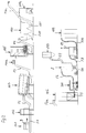
- the system When processing very dirty and wet waste products the system, as can be seen in FIG. 2, around a washing system 110 with heavy goods discharge 111 by means of a Conveyor F11 supplemented after the device 105 for the pre-shredding of the waste material and before Storage container 106 is arranged for the raw material.
- a dewatering press 111a For the Heavy goods discharge is also at the end of the Conveyor F11 a dewatering press 111a intended.
- this system a second device for metal deposition the reservoir 106 is eliminated. From the car wash leads then the conveyor 4a to the reservoir 106.
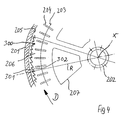
- an impact vortex mill 200 is preferred according to a construction according to the invention, as schematized 3 is used.
- An essential one Feature of the impact vortex mill - impact reactor - 200 is the installation of two fans, each in the entrance area and in the exit area, with different delivery rate such that the upper Fan 213 has a higher output than the lower one Fan 212 has.
- Impact reactor 200 has a stator a two-part drum 201 with upper part 201a and lower part 201b, and a drum base 218 and a cover 217.
- the rotor with shaft 202 is perpendicular with its shaft axis X. stored and is by means of a not shown Drive driven by the pulley 214.
- the receiving plates 203 with knives 204 are spaced from each other by partition plates 219, whereby a grinding stage M1 between the separating plates, M2, M3, M4, M5, M6 with a mounting plate 203 and knives 204 is formed.
- the receiving plates 203 also have large openings 207 so that in each grinding stage Grinding air including particles can swirl.
- a conveyor gap 206 remains in which the grinding air including the particles in the direction of the arrow from the bottom to the bottom worn from grinding stage to grinding stage up to discharge and be sucked.
- the grinding chamber is formed by an intermediate cover 220 with a central opening 221 opposite the top cover 217 of the drum covered.
- the intermediate cover has one central passage opening 221 for the grinding air and the Regrind.
- the profiling in the form of Saw teeth 300 is formed with two flanks 301, 302, the first flank 301 in the direction of rotation D of the shaft 202 each radially on one through the shaft axis X as The center of the radius R runs and the second Flank 302 an acute angle, for example about 40 to 50 ° with the first flank 301 at the sawtooth tip.
- Centrally on the drum base 218 is from one side over the Feed channel 210, the raw meal RM supplied and via a another feed channel 209 the grinding air ML.
- a fan 212 Between Drum bottom and first grinding stage M1 is a fan 212, equipped with fan blades attached to shaft 202 and arranged.
- the grinding air ML takes the raw material RM with it and enters it through the openings in the first grinding stage M1.
- the top grinding stage M6 which in turn by means of a Cutting disc 219 is covered, so that the grinding air and the Solid particles only through the conveyor gap 206 upwards another fan is on shaft 202 213 attached, the one with larger wings and thus with a higher output than the lower fan 212 is equipped.
- the diffuser 216 is the Connection line F6 connected to the silo, one Storage space for the grinding air and the finely divided particles Grist forms and in which a higher pressure than in Impact reactor 200 is maintained. That way the throughput can be controlled by the impact reactor 200, namely the dwell time of the raw material after it has been introduced into the impact reactor via inlet 208 until exit the same at outlet 201.
- the suction can flow into the feed gap 206 of the impact reactor be varied and thus the speed at which the Grinding air and the particles through the individual grinding stages whirl and out of these from grinding stage to grinding stage slowly lift the gap 206 and to be sucked in.
- a back pressure i.e. by arranging a Storage space after the impact reactor, via the connecting line a very low-wear comminution and separation of the Raw grinding material takes place in the impact reactor. It was found that a fine crushing practically only by collisions and Swirling the particles of the raw material together occurs and only to a small extent due to the collision with the fixed construction parts of the impact mill, i.e.
- the number of grinding stages as well as the number of knives each mounting plate of each grinding level depends on the desired performance of the impact reactor and according to manufacturing products.
- an impact reactor as shown with six grinding stages with a diameter of Mounting plates up to a meter at most, a height of one Provide grinding step of about 100 mm, with between 40 to 50 Knives are provided per grinding stage.
- Such an impact reactor can be loaded with one ton of raw meal per hour, 42,000 cbm of grinding air are passed through per hour.
- the silo downstream of the impact reactor should then be one Have storage space of at least 5 cbm.
- the Temperature control of the grinding air takes place, for example a temperature measuring device TM by means of a sensor in the area the exit from the impact reactor, for example on the diffuser 216, see Fig. 3.
- the supply of additional water W can for example via a feed device with controllable Valve 215 in the area of the feed channel 209 for the grinding air respectively.
- the water W is preferably intermittent injected, depending on that on the diffuser 216 measured temperature of the outflowing grinding air.
- thermoplastic plastics temperature control so set that when a grinding air temperature is exceeded of 90 ° C, measured with the temperature measuring device TM, water via the device 215 with the grinding air into the reactor is introduced to the grinding air temperature below 90 ° C hold.
- the amount and the intervals at which Water must also be supplied depend on the one with the Raw ground RM entrained moisture. Furthermore is this also dependent on the dwell time of the raw material in the Impact reactor, which in turn by means of the back pressure from the Storage space and the delivery capacity of the upper fan 213 is controllable.
- the warmth and warming of the grinding air ML within the reactor is controlled exclusively by the Frictional heat of the colliding in the air vortices Particles of the raw material produced during the fine grinding. This also evaporates the moisture inside the Raw meal and is together with the grinding air and the finely ground particles MG as regrind Evaporation product V removed with.
- the system shown schematically in FIG. 5 is suitable for example for the processing of mainly plastic containing waste, this in a relatively clean Condition are delivered, for example film waste processed dry.
- the waste material will for example in the form of a bale, as shown in FIG. 1, placed on a conveyor belt F1 and a bale breaker 102 fed to which a coarse shredder 102a, for example Shredder is subordinated by reducing the waste product to sizes is roughly crushed down to 50 mm. From here it will coarsely shredded material on a conveyor belt F2 transported and a magnetic separator 104a, for example a magnetic tape for iron - Fe - for deposition ferrous metal particles.
- a material pre-cleaning such as Sieve drum 103
- the foreign bodies such as stones, heavy goods, discharged on the underside via the discharge belt 103a and be removed.
- the waste material pre-cleaned in this way is then removed from the sieve drum 103 on a further conveyor belt
- F3 Magnet roller 103b passed and runs through Metal separator 104b for non-ferrous metals.
- a shredder which with Knives is equipped, fed and here on particles one Size smaller than 30 x 30 crushed, including threads be chopped up.
- the now finely shredded waste leaves the shredder 105 and is conveyed via a conveying line F4, which works pneumatically, fed to a storage bunker 106.
- the pre-shredded waste material is transferred from the storage bunker a conveyor line, for example a screw conveyor F5, the Impact reactor 200 fed.
- Impact reactor 200 is one Surround the soundproof hood 200a.
- the finely shredded and disassembled material in the impact reactor together with exhaust air and evaporation products Delivery line F6 is fed to the silo S forming the storage space.
- the evaporation products and exhaust gases leave the silo above via the exhaust duct F7 and become one Air washing device 107a supplied.
- the solid particles are from the silo S via the rotary valve ZR and the pneumatically working delivery line F8 one Dry separator supplied.
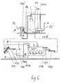
- a Vibrating sieve for separating the water 129 and another Screw conveyor 130 is returned to the system via the Delivery line F4b and then the impact reactor 200 for further Very fine comminution fed. This is a relatively wet waste to be processed in the impact reactor.
- the washing system is supplied with water via the Water inlet Z and water outlet A.
- FIG. 7 schematically shows a plant for processing so-called rejects, i.e. predominantly cellulose-containing Waste materials from the paper industry containing materials shown.
- the waste for example in bales is delivered and dissolved, is then on a conveyor F2 in turn is fed to a screen drum 103 and from here discharged and on the conveyor belt a magnetic separator 104a for Fe with two leveling devices 104c, 104d fed and then another metal separator 104b supplied for non-ferrous metals, which still with a Collection container 104e is equipped.
- the waste can also be between the two Metal separators 104a and 104b another shredder, for example, hammer mill or cutting device.
- Impact reactor 200 with motor 200b is one Surround the soundproof hood 200a. That in the impact protection reactor 200 finely crushed and separated waste, namely the Rejects are fed via the delivery line F6 with the Evaporation products and the exhaust air in the silo S brought in. The exhaust air and vaporization products are over the exhaust duct F7 is removed from the silo and one Air separation supplied with condenser, 107.
- the Solid particles are in the silo S down through a Cell wheel lock ZR carried out via the delivery line F8 and fed to a storage container.
- Drying agents are obtained here from dried cellulose subsequently of further solid particles, such as, for example Plastic particles in a dry separator can be exempted.
Landscapes
- Engineering & Computer Science (AREA)
- Environmental & Geological Engineering (AREA)
- Mechanical Engineering (AREA)
- Food Science & Technology (AREA)
- Crushing And Pulverization Processes (AREA)
- Processing And Handling Of Plastics And Other Materials For Molding In General (AREA)
- Processing Of Solid Wastes (AREA)
- Separation, Recovery Or Treatment Of Waste Materials Containing Plastics (AREA)
- Fertilizers (AREA)
- Combined Means For Separation Of Solids (AREA)
Applications Claiming Priority (2)
| Application Number | Priority Date | Filing Date | Title |
|---|---|---|---|
| DE1997115772 DE19715772C1 (de) | 1997-04-16 | 1997-04-16 | Verfahren und Vorrichtung zum Aufbereiten von Abfallprodukten auf Basis von Kunststoffen |
| DE19715772 | 1997-04-16 |
Publications (3)
| Publication Number | Publication Date |
|---|---|
| EP0872322A2 true EP0872322A2 (fr) | 1998-10-21 |
| EP0872322A3 EP0872322A3 (fr) | 2000-04-19 |
| EP0872322B1 EP0872322B1 (fr) | 2003-01-29 |
Family
ID=7826613
Family Applications (1)
| Application Number | Title | Priority Date | Filing Date |
|---|---|---|---|
| EP98106868A Expired - Lifetime EP0872322B1 (fr) | 1997-04-16 | 1998-04-16 | Procédé et dispositif pour traiter des déchets à base de matières plastiques |
Country Status (3)
| Country | Link |
|---|---|
| EP (1) | EP0872322B1 (fr) |
| AT (1) | ATE231779T1 (fr) |
| DE (3) | DE19715772C1 (fr) |
Cited By (5)
| Publication number | Priority date | Publication date | Assignee | Title |
|---|---|---|---|---|
| MD20130042A2 (ro) * | 2013-07-05 | 2015-01-31 | Институт Химии Академии Наук Молдовы | Procedeu de reciclare a deşeurilor de mase plastice organice |
| EP2788544B1 (fr) | 2011-12-09 | 2016-11-02 | Aerocycle GmbH | Procédé de traitement de vieux papiers |
| CN113306193A (zh) * | 2021-05-21 | 2021-08-27 | 新活力活性炭有限公司 | 一种挤压式活性炭棒制造机 |
| CN113878758A (zh) * | 2021-10-12 | 2022-01-04 | 韶关市中塑再生资源有限公司 | 一种废农地膜再生处理生产线 |
| EP4010122A4 (fr) * | 2019-08-05 | 2022-09-14 | Bernardo Gusman del Campo | Système de classification de broyage de particules et procédé d'utilisation correspondant |
Families Citing this family (10)
| Publication number | Priority date | Publication date | Assignee | Title |
|---|---|---|---|---|
| JP2002001141A (ja) * | 2000-06-23 | 2002-01-08 | Nisshin Seifun Group Inc | 機械式粉砕機 |
| JP4689016B2 (ja) * | 2000-09-12 | 2011-05-25 | 株式会社日清製粉グループ本社 | 機械式粉砕機 |
| DE10149515A1 (de) * | 2001-10-08 | 2003-04-17 | G & A Industrieanlagen Gmbh | Verfahren und Vorrichtung zur Herstellung eines Kunststoffproduktes aus recycelten, mit Zellulosebestandteilen behafteten Kunststoffabfällen |
| DE102006006096A1 (de) * | 2006-02-10 | 2007-08-16 | Altenburger Maschinen Jäckering GmbH | Vorrichtung und Verfahren zur Einspeisung von feuchten und/oder klebrigen Produkten, insbesondere Zellulose, in einer Luftwirbelmühle |
| DE102006034692B4 (de) | 2006-07-27 | 2008-11-20 | Thomas Adamec | Verfahren zum Zerkleinern von Verbundstoffmaterialien |
| DE102015003260A1 (de) | 2015-03-16 | 2016-09-22 | Pallmann Maschinenfabrik Gmbh & Co. Kg | Verfahren zur Zerkleinerung von wärmeempfindlichem Aufgabegut |
| DE102016115714A1 (de) | 2016-08-24 | 2018-03-01 | Schäfer E. Technik u. Sondermaschinen GmbH | Prallreaktor |
| DE102016120467A1 (de) * | 2016-10-26 | 2018-04-26 | Schäfer Elektrotechnik und Sondermaschinen GmbH | Prallreaktor zum Zerkleinern von Verbundmaterial und Verfahren zum Zerkleinern von Verbundmaterial |
| DE102016123543A1 (de) * | 2016-12-06 | 2018-06-07 | Jan Ritter | Verfahren und Vorrichtung zum Aufbereiten von Werkstoffen |
| WO2025221268A1 (fr) * | 2024-04-19 | 2025-10-23 | Equistar Chemicals, Lp | Tri de lldpe et de ldpe et procédés associés |
Family Cites Families (8)
| Publication number | Priority date | Publication date | Assignee | Title |
|---|---|---|---|---|
| US2963230A (en) * | 1954-06-30 | 1960-12-06 | Microcyclomat Co | Dry material pulverizer with integral classifier |
| NL269501A (fr) * | 1960-10-25 | 1900-01-01 | ||
| DE3543370A1 (de) * | 1985-12-07 | 1987-06-11 | Jackering Altenburger Masch | Muehle mit mehreren mahlstufen |
| DE4200827C2 (de) * | 1992-01-15 | 1997-09-04 | Jackering Altenburger Masch | Verfahren und Vorrichtung zur Erfassung von Kunststoff oder Gummi aus einem Abfallgemisch |
| EP0751831B1 (fr) * | 1994-03-23 | 1997-09-17 | Rudolf Engel | Procede et dispositif pour le traitement d'elements composites |
| US5510076A (en) * | 1994-12-02 | 1996-04-23 | Brooks; Thomas W. | Method and apparatus of recycling previously used agricultural plastic film mulch |
| DE29515434U1 (de) * | 1995-09-27 | 1995-11-23 | Mahltechnik Görgens GmbH, 41541 Dormagen | Micro-Wirbel-Mühle |
| DE29515433U1 (de) * | 1995-09-27 | 1995-11-30 | Mahltechnik Görgens GmbH, 41541 Dormagen | Micro-Wirbel-Mühle |
-
1997
- 1997-04-16 DE DE1997115772 patent/DE19715772C1/de not_active Expired - Fee Related
- 1997-04-23 DE DE29707269U patent/DE29707269U1/de not_active Expired - Lifetime
-
1998
- 1998-04-16 DE DE59807038T patent/DE59807038D1/de not_active Expired - Fee Related
- 1998-04-16 EP EP98106868A patent/EP0872322B1/fr not_active Expired - Lifetime
- 1998-04-16 AT AT98106868T patent/ATE231779T1/de not_active IP Right Cessation
Cited By (5)
| Publication number | Priority date | Publication date | Assignee | Title |
|---|---|---|---|---|
| EP2788544B1 (fr) | 2011-12-09 | 2016-11-02 | Aerocycle GmbH | Procédé de traitement de vieux papiers |
| MD20130042A2 (ro) * | 2013-07-05 | 2015-01-31 | Институт Химии Академии Наук Молдовы | Procedeu de reciclare a deşeurilor de mase plastice organice |
| EP4010122A4 (fr) * | 2019-08-05 | 2022-09-14 | Bernardo Gusman del Campo | Système de classification de broyage de particules et procédé d'utilisation correspondant |
| CN113306193A (zh) * | 2021-05-21 | 2021-08-27 | 新活力活性炭有限公司 | 一种挤压式活性炭棒制造机 |
| CN113878758A (zh) * | 2021-10-12 | 2022-01-04 | 韶关市中塑再生资源有限公司 | 一种废农地膜再生处理生产线 |
Also Published As
| Publication number | Publication date |
|---|---|
| ATE231779T1 (de) | 2003-02-15 |
| EP0872322A3 (fr) | 2000-04-19 |
| EP0872322B1 (fr) | 2003-01-29 |
| DE29707269U1 (de) | 1997-08-07 |
| DE19715772C1 (de) | 1998-07-02 |
| DE59807038D1 (de) | 2003-03-06 |
Similar Documents
| Publication | Publication Date | Title |
|---|---|---|
| EP0800445B2 (fr) | Procede et installation de traitement de plastiques mixtes | |
| EP0872322B1 (fr) | Procédé et dispositif pour traiter des déchets à base de matières plastiques | |
| EP0243747A2 (fr) | Procédé et dispositif pour traiter des déchets domestiques, industriels et analogues | |
| EP1047502B1 (fr) | Procede de traitement de dechets mixtes, et installation de traitement et silos tampons utilises a cet effet | |
| DE60300809T2 (de) | Vorrichtung zur Wiedergewinnung von Gipskartonplatten | |
| DE3105597C2 (de) | Abfallaufbereitung | |
| EP0243819B1 (fr) | Procédé et dispositif pour fractionner un mélange hétérogène de matières solides | |
| EP0607790A1 (fr) | Procédé et dispositif pour le traitement des déchets plastiques | |
| DE202012012571U1 (de) | Vorrichtung zum Aufbereiten von Kunststoffmaterial | |
| EP0064596A2 (fr) | Broyeur granulateur pour le broyage de carottes, de pièces moulées par injection, de corps creux soufflés, etc. | |
| WO2003103859A2 (fr) | Procede et dispositif pour le traitement de materiaux, de materiaux composites et de leurs composes | |
| EP0912310B1 (fr) | Procede et dispositif pour le traitement de matieres plastiques mixtes | |
| DE4206054C2 (de) | Verfahren und Vorrichtung zum Herstellen eines Tabakstranges | |
| DE3728899C2 (fr) | ||
| EP2393598B1 (fr) | Dispositif de broyage de matière plastique | |
| EP3895806A1 (fr) | Dispositif et procédé de broyage de matières solides | |
| DE3836608C2 (fr) | ||
| DE102017120043C5 (de) | Anlage und Verfahren zur Herstellung von beleimten Pflanzenpartikeln | |
| DE10336802B4 (de) | Verfahren und Anlage zum Trennen und Sortieren insbesondere von vorzerkleinerten Stoffen | |
| DE3508504A1 (de) | Verfahren zum reinigen von kunststoff-abfaellen | |
| DE2817304C2 (de) | Verfahren zum Gewinnen von festem Brennmaterial aus Abfall | |
| DE4420211C1 (de) | Verfahren und Vorrichtung zur Herstellung von Granulat aus Kunststoffen | |
| DE3201096A1 (de) | Schneidmuehle zum zerkleinern von anguessen, spritzgussteilen, geblasenen hohlkoerpern und dergleichen | |
| DE2547440A1 (de) | Verfahren zum aufbereiten der kunststoffbestandteile von ggf. vorsortierten abfallstoffen | |
| DE29721670U1 (de) | Anordnung zur Zerkleinerung von Körpern aus Hart- bzw. Strukturschaumstoff |
Legal Events
| Date | Code | Title | Description |
|---|---|---|---|
| PUAI | Public reference made under article 153(3) epc to a published international application that has entered the european phase |
Free format text: ORIGINAL CODE: 0009012 |
|
| AK | Designated contracting states |
Kind code of ref document: A2 Designated state(s): AT BE CH DE DK ES FI FR GB GR IT LI NL PT SE |
|
| AX | Request for extension of the european patent |
Free format text: AL;LT;LV;MK;RO;SI |
|
| PUAL | Search report despatched |
Free format text: ORIGINAL CODE: 0009013 |
|
| AK | Designated contracting states |
Kind code of ref document: A3 Designated state(s): AT BE CH CY DE DK ES FI FR GB GR IE IT LI LU MC NL PT SE |
|
| AX | Request for extension of the european patent |
Free format text: AL;LT;LV;MK;RO;SI |
|
| 17P | Request for examination filed |
Effective date: 20001017 |
|
| AKX | Designation fees paid |
Free format text: AT BE CH DE DK ES FI FR GB GR IT LI NL PT SE |
|
| AXX | Extension fees paid |
Free format text: SI PAYMENT 20001017 |
|
| 17Q | First examination report despatched |
Effective date: 20010608 |
|
| GRAG | Despatch of communication of intention to grant |
Free format text: ORIGINAL CODE: EPIDOS AGRA |
|
| GRAG | Despatch of communication of intention to grant |
Free format text: ORIGINAL CODE: EPIDOS AGRA |
|
| GRAH | Despatch of communication of intention to grant a patent |
Free format text: ORIGINAL CODE: EPIDOS IGRA |
|
| GRAH | Despatch of communication of intention to grant a patent |
Free format text: ORIGINAL CODE: EPIDOS IGRA |
|
| GRAA | (expected) grant |
Free format text: ORIGINAL CODE: 0009210 |
|
| AK | Designated contracting states |
Designated state(s): AT BE CH DE DK ES FI FR GB GR IT LI NL PT SE |
|
| AX | Request for extension of the european patent |
Extension state: SI |
|
| PG25 | Lapsed in a contracting state [announced via postgrant information from national office to epo] |
Ref country code: NL Free format text: LAPSE BECAUSE OF FAILURE TO SUBMIT A TRANSLATION OF THE DESCRIPTION OR TO PAY THE FEE WITHIN THE PRESCRIBED TIME-LIMIT Effective date: 20030129 Ref country code: IT Free format text: LAPSE BECAUSE OF FAILURE TO SUBMIT A TRANSLATION OF THE DESCRIPTION OR TO PAY THE FEE WITHIN THE PRESCRIBED TIME-LIMIT;WARNING: LAPSES OF ITALIAN PATENTS WITH EFFECTIVE DATE BEFORE 2007 MAY HAVE OCCURRED AT ANY TIME BEFORE 2007. THE CORRECT EFFECTIVE DATE MAY BE DIFFERENT FROM THE ONE RECORDED. Effective date: 20030129 Ref country code: GR Free format text: LAPSE BECAUSE OF FAILURE TO SUBMIT A TRANSLATION OF THE DESCRIPTION OR TO PAY THE FEE WITHIN THE PRESCRIBED TIME-LIMIT Effective date: 20030129 Ref country code: GB Free format text: LAPSE BECAUSE OF FAILURE TO SUBMIT A TRANSLATION OF THE DESCRIPTION OR TO PAY THE FEE WITHIN THE PRESCRIBED TIME-LIMIT Effective date: 20030129 Ref country code: FR Free format text: LAPSE BECAUSE OF FAILURE TO SUBMIT A TRANSLATION OF THE DESCRIPTION OR TO PAY THE FEE WITHIN THE PRESCRIBED TIME-LIMIT Effective date: 20030129 Ref country code: FI Free format text: LAPSE BECAUSE OF FAILURE TO SUBMIT A TRANSLATION OF THE DESCRIPTION OR TO PAY THE FEE WITHIN THE PRESCRIBED TIME-LIMIT Effective date: 20030129 |
|
| REG | Reference to a national code |
Ref country code: GB Ref legal event code: FG4D Free format text: NOT ENGLISH |
|
| REG | Reference to a national code |
Ref country code: CH Ref legal event code: EP |
|
| REF | Corresponds to: |
Ref document number: 59807038 Country of ref document: DE Date of ref document: 20030306 Kind code of ref document: P |
|
| PG25 | Lapsed in a contracting state [announced via postgrant information from national office to epo] |
Ref country code: AT Free format text: LAPSE BECAUSE OF NON-PAYMENT OF DUE FEES Effective date: 20030416 |
|
| PG25 | Lapsed in a contracting state [announced via postgrant information from national office to epo] |
Ref country code: SE Free format text: LAPSE BECAUSE OF FAILURE TO SUBMIT A TRANSLATION OF THE DESCRIPTION OR TO PAY THE FEE WITHIN THE PRESCRIBED TIME-LIMIT Effective date: 20030429 Ref country code: PT Free format text: LAPSE BECAUSE OF FAILURE TO SUBMIT A TRANSLATION OF THE DESCRIPTION OR TO PAY THE FEE WITHIN THE PRESCRIBED TIME-LIMIT Effective date: 20030429 Ref country code: DK Free format text: LAPSE BECAUSE OF FAILURE TO SUBMIT A TRANSLATION OF THE DESCRIPTION OR TO PAY THE FEE WITHIN THE PRESCRIBED TIME-LIMIT Effective date: 20030429 |
|
| PG25 | Lapsed in a contracting state [announced via postgrant information from national office to epo] |
Ref country code: LI Free format text: LAPSE BECAUSE OF NON-PAYMENT OF DUE FEES Effective date: 20030430 Ref country code: CH Free format text: LAPSE BECAUSE OF NON-PAYMENT OF DUE FEES Effective date: 20030430 Ref country code: BE Free format text: LAPSE BECAUSE OF NON-PAYMENT OF DUE FEES Effective date: 20030430 |
|
| NLV1 | Nl: lapsed or annulled due to failure to fulfill the requirements of art. 29p and 29m of the patents act | ||
| GBV | Gb: ep patent (uk) treated as always having been void in accordance with gb section 77(7)/1977 [no translation filed] |
Effective date: 20030129 |
|
| PG25 | Lapsed in a contracting state [announced via postgrant information from national office to epo] |
Ref country code: ES Free format text: LAPSE BECAUSE OF FAILURE TO SUBMIT A TRANSLATION OF THE DESCRIPTION OR TO PAY THE FEE WITHIN THE PRESCRIBED TIME-LIMIT Effective date: 20030730 |
|
| BERE | Be: lapsed |
Owner name: *CHWIEGER FRIEDHELM Effective date: 20030430 Owner name: *HERRMANN OTTO Effective date: 20030430 |
|
| PLBE | No opposition filed within time limit |
Free format text: ORIGINAL CODE: 0009261 |
|
| STAA | Information on the status of an ep patent application or granted ep patent |
Free format text: STATUS: NO OPPOSITION FILED WITHIN TIME LIMIT |
|
| REG | Reference to a national code |
Ref country code: CH Ref legal event code: PL |
|
| EN | Fr: translation not filed | ||
| 26N | No opposition filed |
Effective date: 20031030 |
|
| PGFP | Annual fee paid to national office [announced via postgrant information from national office to epo] |
Ref country code: DE Payment date: 20080421 Year of fee payment: 11 |
|
| PG25 | Lapsed in a contracting state [announced via postgrant information from national office to epo] |
Ref country code: DE Free format text: LAPSE BECAUSE OF NON-PAYMENT OF DUE FEES Effective date: 20091103 |