EP0872368A2 - Appareil de conditionnement pour véhicule - Google Patents
Appareil de conditionnement pour véhicule Download PDFInfo
- Publication number
- EP0872368A2 EP0872368A2 EP98302963A EP98302963A EP0872368A2 EP 0872368 A2 EP0872368 A2 EP 0872368A2 EP 98302963 A EP98302963 A EP 98302963A EP 98302963 A EP98302963 A EP 98302963A EP 0872368 A2 EP0872368 A2 EP 0872368A2
- Authority
- EP
- European Patent Office
- Prior art keywords
- thermal perception
- air
- conditioning apparatus
- air conditioning
- perception index
- Prior art date
- Legal status (The legal status is an assumption and is not a legal conclusion. Google has not performed a legal analysis and makes no representation as to the accuracy of the status listed.)
- Withdrawn
Links
Images





Classifications
-
- B—PERFORMING OPERATIONS; TRANSPORTING
- B60—VEHICLES IN GENERAL
- B60H—ARRANGEMENTS OF HEATING, COOLING, VENTILATING OR OTHER AIR-TREATING DEVICES SPECIALLY ADAPTED FOR PASSENGER OR GOODS SPACES OF VEHICLES
- B60H1/00—Heating, cooling or ventilating devices
- B60H1/00642—Control systems or circuits; Control members or indication devices for heating, cooling or ventilating devices
- B60H1/0073—Control systems or circuits characterised by particular algorithms or computational models, e.g. fuzzy logic or dynamic models
-
- B—PERFORMING OPERATIONS; TRANSPORTING
- B60—VEHICLES IN GENERAL
- B60H—ARRANGEMENTS OF HEATING, COOLING, VENTILATING OR OTHER AIR-TREATING DEVICES SPECIALLY ADAPTED FOR PASSENGER OR GOODS SPACES OF VEHICLES
- B60H1/00—Heating, cooling or ventilating devices
- B60H1/00642—Control systems or circuits; Control members or indication devices for heating, cooling or ventilating devices
- B60H1/00814—Control systems or circuits characterised by their output, for controlling particular components of the heating, cooling or ventilating installation
- B60H1/00821—Control systems or circuits characterised by their output, for controlling particular components of the heating, cooling or ventilating installation the components being ventilating, air admitting or air distributing devices
- B60H1/00828—Ventilators, e.g. speed control
-
- F—MECHANICAL ENGINEERING; LIGHTING; HEATING; WEAPONS; BLASTING
- F24—HEATING; RANGES; VENTILATING
- F24F—AIR-CONDITIONING; AIR-HUMIDIFICATION; VENTILATION; USE OF AIR CURRENTS FOR SCREENING
- F24F2120/00—Control inputs relating to users or occupants
- F24F2120/20—Feedback from users
Definitions
- the present invention relates to air conditioning apparatus for vehicles, and, more particularly, to air conditioning apparatus with which a passenger in a vehicle may set a desired thermal perception, and one which can maintain that thermal perception in a vehicle compartment precisely and comfortably.
- a known air conditioning apparatus 1' is shown.
- a blower which includes blower fan 7 and blower motor 6, evaporator 8, and heater core 9 are arranged in a sequential manner.
- Inside air inlet opening 3 and outside air inlet opening 4 are provided.
- Air introduced into ventilation duct 2 may be selected either from air inside the passenger compartment, or from air outside the passenger compartment, by switching damper 5, in accordance with a passenger's selection.
- three air discharge ports, 19, 20, and 21 (each corresponding to a specific output location, e.g., DEF, VENT, and FOOT, respectively) are provided.
- Each ofthrce air discharge ports 19, 20, and 21, is provided with damper 22, 23, and 24, respectively, which is opened or closed in accordance with the passenger's selection.
- Refrigerant circuit 11 comprises expansion valve 15, evaporator 8, variable capacity compressor 12, condenser 13, and reservoir tank 14.
- Suction pressure controller 16 regulates the suction pressure of the refrigerant gas sucked into variable capacity compressor 12, and thus adjusts the refrigerating power of refrigerant circuit 11. In other words, the ability of evaporator 8 to cool the air flowing within ventilation duct 2 is controlled by suction pressure controller 16.
- Air damper 17 is provided for heater core 9, and is located immediately downstream of heater core 9. Air mix damper 17 adjusts the relative quantities of air flowing through heater core 9 and air bypassing heater core 9. Air mix damper actuator 18 regulates the position of air mix damper 17. In other words, the ability of heater core 9 to heat the air flowing through ventilation duct 2 is controlled by air mix damper actuator 18.
- blower voltage controller 30 controls the voltage supplied to blower motor 6.
- Suction pressure controller 16 controls the degree of cooling of the air, and air mix damper actuator 18 controls the degree of warming of the air.
- Ambient temperature sensor 28, room temperature sensor 27, radiant light sensor 29, and room temperature setting unit 26 generate signals, and these signals are input into main controller 25.
- Main controller 25 processes these signals, and outputs control signals to the three controllers, i.e. , blower voltage controller 30, suction pressure controller 16, and air mix damper actuator 18.
- a signal processing chart of main controller 25 is shown.
- Ambient temperature sensor 28 sends ambient temperature signal AMB to main controller 25.
- Radiant light sensor 29 detects the amount of sunlight shining on sensor 29 and sends sunlight quantity signal RAD to main controller 25.
- Room temperature sensor 27 sends room temperature signal TR to main controller 25.
- Room temperature setting unit 26 sends objective room temperature signal TV to main controller 25.
- the value of control signals for the three controllers i.e. , blower voltage controller 30, suction pressure controller 16, and air mix damper actuator 18 are determined.
- TINh is given by: where f is an appropriately designed function, BLV is given by equation (2), and PS is given by equation (4), below.
- Known air conditioning apparatus 1' shows a typical responsive behavior against a change in an external condition.
- Fig. 3(a) a response of air conditioning apparatus 1' when a vehicle moves from the direct sunlight and into the shadows is illustrated.
- radiant light sensor 29 detects a decrease in direct sunlight quantity, and sends a corresponding signal, RAD, representing that information to main controller 25.
- Main controller 25 calculates objective outlet temperature TOs, which rises due to a decrease in RAD, the second term of equation (1) .
- the upper thin curve indicates objective outlet air temperature TOs, and the upper bold curve represents the actual outlet air temperature.
- the rise in the actual outlet air temperature is indicated by U1.
- the lower thin horizontal line indicates objective room temperature TV, and lower bold curve indicates room temperature TR.
- room temperature TR stays at approximately the same value.
- known air conditioning apparatus 1' maintains room temperature TR to be the same as objective room temperature TV, set in room temperature setting unit 26.
- known air conditional apparatus 1' controls the room temperature to become a desired value, which is set by the passenger, and continuously maintains this value.
- the degree of comfortableness afforded by an air conditioning apparatus does not depend solely on the room temperature.
- the degree of comfortableness a passenger perceives depends on several factors, including, inter alia , the passenger's metabolic rate, the amount of clothing the passenger is wearing, the air temperature, the radiation temperature, the air flow, and the humidity.
- the most important factors are the air temperature, the radiation temperature, the air flow, and the clothing amount. In other words, they are the room temperature in the vehicle, the ambient temperature outside the vehicle, the quantity of sunlight directed onto the outside the vehicle, the air flow quantity discharged from the air conditioning apparatus, and the amount of clothing the passenger is wearing,
- the PMV value is based on heat balance of the human body.
- a person is in thermal balance when the internal heat production in the body is equal to the loss of heat to the environment.
- a person's thermoregulator system will automatically try to modify the skin temperature and the sweat secretion to maintain heat balance.
- PMV (0.303 e -0.036 M + 0.028) [( M - W ) - 3.05 ⁇ 10 -3 ⁇ [5733 - 6.99 ( M - W ) - p a ] - 0.42 ⁇ [( M - W ) - 58.15] - 1.7 ⁇ 10 -5 M (5867 - p a ) - 0.0014 M (34 - t a ) - 3.96 ⁇ 10 -8 f cl ⁇ [( f cl + 273) 4 - t r + 273) 4 ] - f cl h c ( t cl - t a ) where
- the PMV value becomes a measurable quantity if assumptions concerning the value of some of the parameters (e.g. , the metabolic rate, clothing amount, and humidity) are made, or if these parameters are measured or otherwise determined and input.
- the lower bold curve indicates an estimated PMV value.
- D1 the PMV value decreases stepwisely when the vehicle moves from the direct sunlight and into shadow, indicating that the passenger experiences a thermal perception that is not the desired one.
- the room temperature does not change significantly, the passenger feels slightly cool and uncomfortable.
- a change in the PMV value may be caused by the changes in the air flow quantity or in the ambient temperature, giving the passenger an undesired thermal perception.
- This problem arises because the known air conditioning apparatus 1' controls the value for room temperature TR first. Accordingly, if it is possible to control the PMV value or other thermal perception index first instead of controlling the room temperature TR first, the performance of an air conditioning apparatus will improve.
- an air conditioning apparatus that controls a thermal perception index first. Accordingly, it is a technical advantage ofthe present invention to provide a vehicular air conditioning apparatus that conditions air, based on a thermal perception index. Another technical advantage ofthe present invention it that it provides a vehicular air conditioning apparatus that determines the thermal perception index inside of a vehicle, from several state variables, and controls the thermal perception index inside the vehicle to reach and maintain a passenger's desired level.
- the air conditioning apparatus of the present invention comprises a blower, an evaporator, a heater core, and an air mix damper, which are arranged sequentially within the ventilation duct, and a refrigeration circuit.
- Room temperature sensor, ambient temperature sensor, and radiant light sensor are connected to a main controller.
- a thermal perception index setting unit is further connected to the main controller.
- the main controller processes signals originating from these sensors, and provides control signals for a blower voltage controller, a suction pressure controller, and a air mix damper actuator.
- the air conditioning apparatus of the present invention presumes the current PMV value, i.e. , one type of thermal perception index, by calculating it from several state variables, and the controls the blower, the evaporator, and the air mix damper, based upon a difference between the presumed PMV value and the passenger's desired PMV value, set in a PMV value setting unit.
- Fig. 1 is a hardware diagram of a known air conditioning apparatus.
- Fig. 2 is a control flow diagram of a known air conditioning apparatus.
- Fig. 3 is a simulation diagram of response characteristics of a known air conditioning apparatus.
- Fig. 4 is a first control embodiment of the present invention of an air conditioning apparatus.
- Fig. 5 is a second control embodiment of the present invention of an air conditioning apparatus.
- Fig. 6 is a hardware diagram of an air conditioning apparatus according to the second control embodiment of the present invention.
- Fig. 7 is a control flow diagram of an air conditioning apparatus of Fig. 6 .
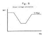
- Fig. 8 is a diagram of the functional relationship for determining the blower voltage.
- Fig. 9 is a simulation diagram of a response characteristic of an air conditioning apparatus of Fig. 6 .
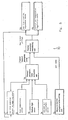
- a first control embodiment 60 of the present invention is shown.
- the current thermal perception index is calculated from room temperature sensor 61 and current blower voltage 62.
- a new blower control voltage and outlet air temperature are computed in box 65, and are sent to air flow quantity regulation means 66, and to outlet air temperature regulation means 67.
- a second control embodiment 70 of the present invention of an air conditioning apparatus is depicted.
- the current thermal perception index is calculated from current blower voltage 71, room temperature 72, direct sunlight quantity 73, and ambient temperature 74.
- new blower control voltage and outlet air temperature are computed in box 77, and are sent to air flow quantity regulation means 78 and outlet air temperature regulations means 79.
- TW is the engine coolant water temperature.
- PS f(TOS, BLV, TINe) where f is an appropriately designed function, which may be linear in TOS, BLV, and TINe, and has negative dependence on TINe.
- Constants a, b, c, d, e, g, h, i, j, Ki, Kp1, Kp2, and delta may be defined as shown in Table 1 : Constants Range of Values Meaning a about 0. 1 to about 0.5 Room temperature dependence b about 0.0 to about 0.1 Ambient temperature dependence c about 0.2 to about 0.8 Direct sunlight dependence d about-0.5 to about 0.0 Blower intensity dependence e about-20 to about +20 Total offset g about 0.0 to about 0. 1 Ambient temperature dependence h about 0.2 to about 0.8 Direct sunlight dependence i about 0.
- Air conditioning apparatus 1 shows a response characteristic, illustrated in Fig. 9 .
- the actual outlet air temperature rises more than in known air conditioning apparatus l' when the vehicle moves from direct sunlight and into the shadows (compare U1 in Fig. 3(a) and U2 in Fig. 9(a) .)
- room temperature TR indicated by the lower bold curve in Fig. 9(a) rises slightly (indicated by U3).
- the actual PMV value does not deviate substantially in response to a change in external condition, as seen from the bold curve in Fig. 9(b) . Therefore, the passenger senses little or no change in thermal perception In other words, even if the vehicle goes into shadow from direct sunlight, the passenger does not feel cooler because the control mechanism increases the room temperature by an appropriate amount.
- the passenger's thermal perception i.e. , the PMV value
- the PMV value the passenger's thermal perception
- a PMV value is adopted as a thermal perception index in an air conditioning apparatus, illustrated in Fig. 6
- this invention is not restricted thereto.
- action temperature, equivalent temperature, effective temperature, or new effective temperature may be employed as substitutes for a thermal perception index.
- equation (5) should be replaced by a corresponding equation.
- the PMV setting unit of an air conditioning apparatus of the present invention may have a range of from about -1.5 to about +1.5.
- any appropriate scale may be used on the PMV setting unit.
- An example of such a scale may be about +18 to about +32, where about +18 is equivalent to about a -1.5 PMV value, about +25 is equivalent to about a 0 PMV value, and about +32 is equivalent to about a +1.5 PMV value.
- Other scales, such as from about +65 to about +95, for example, may also be used.
Landscapes
- Physics & Mathematics (AREA)
- Engineering & Computer Science (AREA)
- Thermal Sciences (AREA)
- Mechanical Engineering (AREA)
- Fuzzy Systems (AREA)
- Mathematical Physics (AREA)
- Software Systems (AREA)
- Theoretical Computer Science (AREA)
- Air-Conditioning For Vehicles (AREA)
Applications Claiming Priority (3)
| Application Number | Priority Date | Filing Date | Title |
|---|---|---|---|
| JP11518797 | 1997-04-16 | ||
| JP11518797 | 1997-04-16 | ||
| JP115187/97 | 1997-04-16 |
Publications (2)
| Publication Number | Publication Date |
|---|---|
| EP0872368A2 true EP0872368A2 (fr) | 1998-10-21 |
| EP0872368A3 EP0872368A3 (fr) | 2000-03-22 |
Family
ID=14656517
Family Applications (1)
| Application Number | Title | Priority Date | Filing Date |
|---|---|---|---|
| EP98302963A Withdrawn EP0872368A3 (fr) | 1997-04-16 | 1998-04-16 | Appareil de conditionnement pour véhicule |
Country Status (2)
| Country | Link |
|---|---|
| EP (1) | EP0872368A3 (fr) |
| TW (1) | TW372268B (fr) |
Cited By (8)
| Publication number | Priority date | Publication date | Assignee | Title |
|---|---|---|---|---|
| EP0968855A1 (fr) * | 1998-06-04 | 2000-01-05 | Sanden Corporation | Appareil de conditionnement pour véhicule |
| EP1044834A1 (fr) * | 1999-04-13 | 2000-10-18 | GKR Gesellschaft für Fahrzeugklimaregelung mbH | Procédé pour régler la temperature intérieure d'un véhicule à moteur avec un dispositif de chauffage et de climatisation |
| EP0876930A3 (fr) * | 1997-05-07 | 2001-05-16 | Hella KG Hueck & Co. | Dispositif de climatisation pour l'habitacle d'un véhicle |
| EP1040945A3 (fr) * | 1999-03-31 | 2002-05-02 | Bayerische Motoren Werke Aktiengesellschaft | Procédé d'utilisation d'un dispositif de chauffage/climatisation d'un véhicule et dispositif pour la réalisation de ce procédé |
| EP1190877A3 (fr) * | 2000-09-25 | 2003-07-02 | Behr-Hella Thermocontrol GmbH | Dispositif de régulation de la capacité de chauffage et de refroidissement dans les installations de climatisation de véhicule |
| CN105196833A (zh) * | 2015-10-21 | 2015-12-30 | 惠州华阳通用电子有限公司 | 一种车载节能自动空调控制方法及装置 |
| CN105437923A (zh) * | 2015-11-26 | 2016-03-30 | 惠州华阳通用电子有限公司 | 一种车内湿度自动调节方法及系统 |
| CN109109887A (zh) * | 2018-09-04 | 2019-01-01 | 上海科泰运输制冷设备有限公司 | 一种车辆空调温度控制方法以及系统 |
Family Cites Families (5)
| Publication number | Priority date | Publication date | Assignee | Title |
|---|---|---|---|---|
| JPS62299421A (ja) * | 1986-06-18 | 1987-12-26 | Mazda Motor Corp | 車輛用空気調和装置 |
| EP0522561B2 (fr) * | 1991-07-10 | 2002-07-24 | Naldec Corporation | Méthode et dispositif de commande d'une installation de conditionnement d'air montée sur un véhicule |
| US5170935A (en) * | 1991-11-27 | 1992-12-15 | Massachusetts Institute Of Technology | Adaptable control of HVAC systems |
| IT1261538B (it) * | 1993-04-01 | 1996-05-23 | Fiat Auto Spa | Procedimento per il controllo delle condizioni termiche in un ambientee relativo sistema. |
| JP3429673B2 (ja) * | 1997-04-16 | 2003-07-22 | サンデン株式会社 | 車両用空調装置 |
-
1998
- 1998-04-15 TW TW087105704A patent/TW372268B/zh active
- 1998-04-16 EP EP98302963A patent/EP0872368A3/fr not_active Withdrawn
Non-Patent Citations (1)
| Title |
|---|
| None |
Cited By (9)
| Publication number | Priority date | Publication date | Assignee | Title |
|---|---|---|---|---|
| EP0876930A3 (fr) * | 1997-05-07 | 2001-05-16 | Hella KG Hueck & Co. | Dispositif de climatisation pour l'habitacle d'un véhicle |
| EP0968855A1 (fr) * | 1998-06-04 | 2000-01-05 | Sanden Corporation | Appareil de conditionnement pour véhicule |
| EP1040945A3 (fr) * | 1999-03-31 | 2002-05-02 | Bayerische Motoren Werke Aktiengesellschaft | Procédé d'utilisation d'un dispositif de chauffage/climatisation d'un véhicule et dispositif pour la réalisation de ce procédé |
| EP1044834A1 (fr) * | 1999-04-13 | 2000-10-18 | GKR Gesellschaft für Fahrzeugklimaregelung mbH | Procédé pour régler la temperature intérieure d'un véhicule à moteur avec un dispositif de chauffage et de climatisation |
| EP1190877A3 (fr) * | 2000-09-25 | 2003-07-02 | Behr-Hella Thermocontrol GmbH | Dispositif de régulation de la capacité de chauffage et de refroidissement dans les installations de climatisation de véhicule |
| CN105196833A (zh) * | 2015-10-21 | 2015-12-30 | 惠州华阳通用电子有限公司 | 一种车载节能自动空调控制方法及装置 |
| CN105437923A (zh) * | 2015-11-26 | 2016-03-30 | 惠州华阳通用电子有限公司 | 一种车内湿度自动调节方法及系统 |
| CN109109887A (zh) * | 2018-09-04 | 2019-01-01 | 上海科泰运输制冷设备有限公司 | 一种车辆空调温度控制方法以及系统 |
| CN109109887B (zh) * | 2018-09-04 | 2019-12-10 | 上海科泰运输制冷设备有限公司 | 一种车辆空调温度控制方法以及系统 |
Also Published As
| Publication number | Publication date |
|---|---|
| EP0872368A3 (fr) | 2000-03-22 |
| TW372268B (en) | 1999-10-21 |
Similar Documents
| Publication | Publication Date | Title |
|---|---|---|
| US6202934B1 (en) | Air conditioner for a vehicle having infrared ray sensor | |
| KR100867365B1 (ko) | 공기 조절 제어 장치 | |
| US6719624B2 (en) | Vehicle air conditioning system with seat air conditioner | |
| KR100292175B1 (ko) | 자동차 hvac 장치를 제어하는 방법 및 제어장치 | |
| US5209079A (en) | Control apparatus for air conditioner used for vehicles | |
| US20040164171A1 (en) | Dual zone automatic climate control algorithm utilizing heat flux analysis | |
| US20020125334A1 (en) | Regulation of the temperature, the speed and the distribution of the air blown into a motor-vehicle passenger compartment | |
| EP1588874B1 (fr) | Méthode de compensation du rayonnement solaire pour conditionneur d'air d'un véhicule | |
| EP0968855A1 (fr) | Appareil de conditionnement pour véhicule | |
| EP0872368A2 (fr) | Appareil de conditionnement pour véhicule | |
| KR100727352B1 (ko) | 차량용 공조시스템의 제어방법 | |
| JPH06457B2 (ja) | 空気調和装置の温度制御方法 | |
| JP2002127728A (ja) | 車両用空調装置 | |
| JP4443294B2 (ja) | 車両用空調装置 | |
| US5676204A (en) | Air conditioner for use in a vehicle | |
| EP0539508B1 (fr) | Dispositif de climatisation selective pour l'habitacle d'un vehicule automobile | |
| EP1362725B1 (fr) | Dispositif de contrôle | |
| JP3429673B2 (ja) | 車両用空調装置 | |
| JPH01289712A (ja) | 車両用空調装置の風量制御装置 | |
| JPH111112A (ja) | 車両用空調装置 | |
| JP2902472B2 (ja) | 空調制御装置 | |
| JP3155045B2 (ja) | 車両用空調装置 | |
| JP3493895B2 (ja) | 自動車用空調制御装置 | |
| JP2921290B2 (ja) | 自動車用空調装置 | |
| JP3471230B2 (ja) | 車両用空調装置 |
Legal Events
| Date | Code | Title | Description |
|---|---|---|---|
| PUAI | Public reference made under article 153(3) epc to a published international application that has entered the european phase |
Free format text: ORIGINAL CODE: 0009012 |
|
| AK | Designated contracting states |
Kind code of ref document: A2 Designated state(s): DE FR GB IT SE |
|
| AX | Request for extension of the european patent |
Free format text: AL;LT;LV;MK;RO;SI |
|
| PUAL | Search report despatched |
Free format text: ORIGINAL CODE: 0009013 |
|
| AK | Designated contracting states |
Kind code of ref document: A3 Designated state(s): AT BE CH CY DE DK ES FI FR GB GR IE IT LI LU MC NL PT SE |
|
| AX | Request for extension of the european patent |
Free format text: AL;LT;LV;MK;RO;SI |
|
| 17P | Request for examination filed |
Effective date: 20000912 |
|
| AKX | Designation fees paid |
Free format text: DE FR GB IT SE |
|
| 17Q | First examination report despatched |
Effective date: 20020430 |
|
| STAA | Information on the status of an ep patent application or granted ep patent |
Free format text: STATUS: THE APPLICATION IS DEEMED TO BE WITHDRAWN |
|
| 18D | Application deemed to be withdrawn |
Effective date: 20020911 |