EP0872376A2 - Sitzanordnung in einem Kraftfahrzeug und Kindersitz hierfür - Google Patents
Sitzanordnung in einem Kraftfahrzeug und Kindersitz hierfür Download PDFInfo
- Publication number
- EP0872376A2 EP0872376A2 EP98105572A EP98105572A EP0872376A2 EP 0872376 A2 EP0872376 A2 EP 0872376A2 EP 98105572 A EP98105572 A EP 98105572A EP 98105572 A EP98105572 A EP 98105572A EP 0872376 A2 EP0872376 A2 EP 0872376A2
- Authority
- EP
- European Patent Office
- Prior art keywords
- seat
- child seat
- vehicle
- child
- bracket
- Prior art date
- Legal status (The legal status is an assumption and is not a legal conclusion. Google has not performed a legal analysis and makes no representation as to the accuracy of the status listed.)
- Withdrawn
Links
- 238000010521 absorption reaction Methods 0.000 claims description 5
- 230000003213 activating effect Effects 0.000 claims description 2
- 238000012432 intermediate storage Methods 0.000 claims 1
- 230000004913 activation Effects 0.000 description 1
- 230000006378 damage Effects 0.000 description 1
- 230000006735 deficit Effects 0.000 description 1
- 230000000694 effects Effects 0.000 description 1
- 230000001771 impaired effect Effects 0.000 description 1
- 239000002184 metal Substances 0.000 description 1
- 230000007704 transition Effects 0.000 description 1
Images



Classifications
-
- B—PERFORMING OPERATIONS; TRANSPORTING
- B60—VEHICLES IN GENERAL
- B60N—SEATS SPECIALLY ADAPTED FOR VEHICLES; VEHICLE PASSENGER ACCOMMODATION NOT OTHERWISE PROVIDED FOR
- B60N2/00—Seats specially adapted for vehicles; Arrangement or mounting of seats in vehicles
- B60N2/24—Seats specially adapted for vehicles; Arrangement or mounting of seats in vehicles for particular purposes or particular vehicles
- B60N2/26—Seats specially adapted for vehicles; Arrangement or mounting of seats in vehicles for particular purposes or particular vehicles for children
- B60N2/28—Seats readily mountable on, and dismountable from, existing seats or other parts of the vehicle
- B60N2/2857—Seats readily mountable on, and dismountable from, existing seats or other parts of the vehicle characterised by the peculiar orientation of the child
- B60N2/286—Seats readily mountable on, and dismountable from, existing seats or other parts of the vehicle characterised by the peculiar orientation of the child forward facing
-
- B—PERFORMING OPERATIONS; TRANSPORTING
- B60—VEHICLES IN GENERAL
- B60N—SEATS SPECIALLY ADAPTED FOR VEHICLES; VEHICLE PASSENGER ACCOMMODATION NOT OTHERWISE PROVIDED FOR
- B60N2/00—Seats specially adapted for vehicles; Arrangement or mounting of seats in vehicles
- B60N2/24—Seats specially adapted for vehicles; Arrangement or mounting of seats in vehicles for particular purposes or particular vehicles
- B60N2/26—Seats specially adapted for vehicles; Arrangement or mounting of seats in vehicles for particular purposes or particular vehicles for children
- B60N2/28—Seats readily mountable on, and dismountable from, existing seats or other parts of the vehicle
- B60N2/2839—Seats readily mountable on, and dismountable from, existing seats or other parts of the vehicle having a front guard or barrier
-
- B—PERFORMING OPERATIONS; TRANSPORTING
- B60—VEHICLES IN GENERAL
- B60N—SEATS SPECIALLY ADAPTED FOR VEHICLES; VEHICLE PASSENGER ACCOMMODATION NOT OTHERWISE PROVIDED FOR
- B60N2/00—Seats specially adapted for vehicles; Arrangement or mounting of seats in vehicles
- B60N2/24—Seats specially adapted for vehicles; Arrangement or mounting of seats in vehicles for particular purposes or particular vehicles
- B60N2/26—Seats specially adapted for vehicles; Arrangement or mounting of seats in vehicles for particular purposes or particular vehicles for children
- B60N2/28—Seats readily mountable on, and dismountable from, existing seats or other parts of the vehicle
- B60N2/2887—Fixation to a transversal anchorage bar, e.g. isofix
Definitions
- the invention relates to a seat arrangement in a motor vehicle, especially in a passenger compartment of a passenger car, with a vehicle seat attached to a vehicle floor, which has a seat cushion and a backrest, and with a child seat that can be positioned on the vehicle seat and by means of a child-resistant fastener on at least a holder of the vehicle seat in its functional position can be locked, which is used to lock the child seat between the backrest and the seat cushion on the vehicle seat is, as well as a child seat to be fixed on a vehicle seat of a motor vehicle with a dimensionally stable plastic shell as well as upholstery for a seating area of the child seat.
- Such a seat arrangement is for a passenger seat of a passenger car well known. It is between one Backrest and a seat cushion of the front passenger seat are rigid arranged bracket provided with the one on a child seat Arranged lock can be locked as soon as the child seat brought into its functional position on the vehicle seat is. This locks the child seat directly with achieved the load-bearing parts of the vehicle seat.
- the object of the invention is a seat arrangement and a Child seat of the type mentioned to create an improved Allowing child safety in a motor vehicle.
- this object is achieved in that the Bracket on the vehicle seat between the functional position for locking of the child seat and one hidden by the backrest Rest position swiveling along a movement path is stored, for an unimpeded pivoting of the Bracket between the functional and the rest position on one Free space between the seat cushion and the backrest when folded down Condition is matched.
- the seating comfort on the vehicle seat is therefore not affected the protruding between the seat cushion and the backrest Bracket impaired.
- the bracket can in particular simply from their functional position to their rest position be pivoted by first moving the backrest forward folded down and then the bracket through the resulting Free space is pivoted backwards.
- the child seat fixed closure an actuator for unlocking the lock assigned to the child seat.
- the actuating element Through simple manual operation of the actuating element, the child seat can thus be made released its functional position on the vehicle seat and from the Vehicle are removed.
- At least one other Bracket for locking a child seat in the motor vehicle arranged fixed to the body.
- the at least one more Bracket can be in a hold and / or elsewhere in the car Motor vehicle be arranged fixed to the body.
- the fixed arrangement can be designed indirectly or directly on the body.
- the further holder in a footwell in the direction of travel in front of the vehicle seat Locking a child seat provided on the vehicle floor or is fixed to the vehicle seat.
- the bracket in the footwell is advantageously designed such that in the footwell the same child seat as on the vehicle seat is positionable.
- a wedge-shaped Support element provided in the footwell on the vehicle floor is positionable to the child seat in one of the functional position position in the footwell corresponding to the vehicle seat align.
- the wedge-shaped support element thus ensures that the child's sitting position in the child seat of the footwell from its inclination to the seating position of the child seat on the vehicle seat.
- a support tube frame is provided by the plastic shell is encased.
- the support tube frame can either partially or completely covered by the plastic shell.
- the Support tube frame integrated into the plastic shell increases the Stability and stiffness of the plastic shell considerably, so that the child seat without impairments increased loads is vulnerable.
- the support tube frame extends into all Areas of the plastic shell and thus both in a floor and also in a backrest area of the plastic shell as well in an armrest area.
- the holder is a electronic switch to activate or deactivate a Airbag unit arranged in front of the vehicle seat depending on the Locking the child seat assigned.
- a Airbag unit arranged in front of the vehicle seat depending on the Locking the child seat assigned.
- pivoting catch table is arranged on the catch table at least one strap end of a shoulder strap fixed, the one with its at least one opposite belt end in a backrest of the child seat is held. If two Shoulder strap parts are provided, these are preferably extendable and designed to be automatically retractable. At only A shoulder strap preferably runs diagonally from the Backrest to the opposite of the swivel bearing of the catch table Side of the catch table, which makes the shoulder strap does not have to have an automatic retraction device. In both In cases, the shoulder strap becomes advantageous with the pivoting the catch table in its safety position automatically in its Functional position transferred so that an additional belting of the child after the catch table is closed.
- the catch table has Baffle cushion on, the height adjustable - on a seat of the Child seat covered - is held on a catch table console.
- the impact cushion can also be used adjustable in width relative to the child's sitting position be, so that there is a combined height and width adjustability results.
- the impact cushion has several parallel and one above the other, in the direction of travel open slot recordings, each in their clear height identically designed and alternatively on one with the catching table console connected crossbar are plugged so that a Due to the slotted receptacle attached to one of the seating areas the back of the crossbar facing the child seat supports.
- the crossbar is below Interim storage of energy absorption elements on the collecting table console held. This will result in a vehicle collision the child's impact on the catch table and the impact cushion subdued.
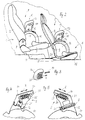
- a passenger car has one on a passenger side Vehicle seat 1 according to FIGS. 1 and 2, with a foldable Backrest 2 and a seat cushion 3 is provided.
- Vehicle seat 1 is on a vehicle floor by means of a seat console 4 of the passenger car.
- a footwell 6 which follows front through a cockpit (not shown) and a bulkhead is limited.
- a cockpit not shown
- Way integrated a passenger airbag unit In the cockpit is also not shown Way integrated a passenger airbag unit.
- the backrest 2 can be folded forward about a folding axis 7 in the direction of travel and from this folded position back to the upright position Swiveling seating position.
- a child seat 8 is positioned on the vehicle seat 1 from a stable support tube frame 9 and a stiff, the Carrier tube frame 9 encasing plastic shell 10 is formed.
- a seating area of the child seat 8 there is an unspecified one Upholstery provided.
- the child seat 8 has one Catching table 11 on the armrests of the unspecified Child seat 8 positioned using a catch table bracket 12 is and extends across the seating position of the child seat 8.
- the catching table 11 has an impact cushion 13 (FIG. 3), that can be plugged onto a crossbar 14 of the collecting table console 12 is.
- the baffle cushion 13 is not shown dimensionally stable insert in which three parallel and slot receptacles 26 arranged one above the other are provided, designed open to the sides and in the direction of travel are.
- the height of the three slot receptacles 26 is in each case designed identically and to the thickness of the crossbar 14 such adjusted that one of the slot receptacles 26 non-positively can be plugged onto the crossbar 14 in the direction of arrow A.
- the Attach in the direction of travel, so that the reason everyone Slot receptacle 26 on the seat area of the child seat 8 facing back of the crossbar 14 strikes.
- the Slot recordings of the impact cushion at different depths see above that the impact cushion can be attached to the crossbar at different distances is. This is a width adjustment of the impact cushion possible because the impact cushion in this way in different Clearances positioned to the backrest of the child seat is. Also by displacing the slot receptacles at an angle to each other there is a width adjustability, which by a oppositely sloping end facing the backrest the impact cushion surface can still be improved.
- the crossbar 14 is on its opposite side with each provide a guide carriage, not shown, of the corresponding sliding guides 23 of bases of the Collecting table bracket 12 is slidably held in the direction of arrow R. are (Figs. 4 and 5).
- the guide sled and thus the Crossbar 14 are via a pivot point 24 by means of an energy absorption element 22 fixed to the catching table console 12, that is deformable in the direction of the arrow R with absorption of energy is.
- each is Energy absorption element 22 as a meandering or bellows-like Sheet metal part designed that when appropriate loads occur is pulled apart in the direction of arrow R.
- the Catch table 11 on a side catch table console 12 by one Swivel axis S is pivotally mounted. This is the catch table 11 from its illustrated securing position into a Release position can be swiveled up for entry and exit is suitable for a child.
- a strap end 18 of a shoulder strap 17 which extends from the strap end 18th diagonally upwards towards the backrest of the child seat 8 extends and in the backrest, preferably on the support tube frame 9 held by means of a corresponding belt loop is.
- This arrangement of the shoulder strap 17 is the shoulder belt 17 automatically in its securing position, as soon as the catch table 11 is pivoted into its securing position is.
- the shoulder strap 17 is with a length adjustment device, not shown provided that the setting for different Children's sizes allowed.
- On the swivel bearing 25 and thus the side opposite the pivot axis S is the Swiveling table 8 by means of a lock 21 on a seat-fixed Base of the catching table console 12 can be fixed, the lock 21st can be released in a simple manner by an actuating button 15.
- the lock 21 represents a mechanical lock known per se represents, the pivoting part of the catch table 8 the actual Lock 21 and the base of the table console 12 a Lock tongue is assigned.
- the child seat 8 is on a vehicle seat-fixed bracket in its functional position on the vehicle seat 1 (Fig. 2) can be determined.
- the seat-fixed holder has two locking brackets 19 on, in their functional position between a lower edge of the backrest 2 and the seat cushion 3 project forward (Fig. 1 and 6 to 10).
- Both locking brackets are by means of appropriate Boom held on a common swivel shaft by one to the folding axis 7 parallel pivot axis 27 is rotatable.
- This pivot axis 27 are the two locking bracket 19 together the functional position can be pivoted back into a rest position and from this rest position back to the Function position swiveling.
- the locking brackets are in the rest position 19 behind the seat cushion 3 and behind the backrest 2 arranged.
- the locking bracket 19 along a path of movement indicated in FIG. 8 between the Backrest 2 and the seat cushion passed through.
- the backrest 2 is forward folded down so that they are in the positions shown in FIG. 7 to 9.
- the arched shape of the boom as an extension to the swivel shaft is designed such that the movement path the locking bracket 19 only passes through this free space.
- the booms also have a certain spring effect.
- FIGS. 8 and 9 In its functional position according to FIGS. 8 and 9, in which the Locking bracket 19 are preferably blocked, serve the locking bracket 19 for holding the child seat 8 on the vehicle seat 1 in its functional position.
- the receiving slots 19 corresponding receiving slots provided, in each of which a mechanical closure 29 provided in the form of a spring-loaded pawl is.
- the lock is integrated in the child seat.
- Via a central Lever joint 30 are the two pawls in the two Locking slots of the child seat 8 by an operating lever 31 releasable, the inside of the child seat 8 to the back of the Child seat protrudes and enables manual operation.
- an actuator can also other places on the child seat 8, which is a simple Enable accessibility.
- brackets 20 are fixed on the vehicle floor 5, which correspond to the locking brackets 19 in their function.
- the bracket However, 20 are not pivotable, but rigid on Vehicle floor 5 arranged and protrude forward into the footwell 6 into it.
- another is identical Child seat 8 designed for child seat 8 can be positioned in the footwell and lockable, so that on the passenger side two child seats can be arranged one behind the other.
- the brackets 20 is an electronic one, not shown Switch for activating and deactivating the passenger airbag assigned.
- a support wedge 16th under one foot of the child seat 8 the child seat so inclined that it also supports the backrest of the child seat 8 on a front edge of the seat cushion 3 of the Vehicle seat 1 takes place.
- a functional one Seating position also reached for the front child seat 8.
- the support wedge 16 is not required, it can be done in a simpler manner Way be removed from the vehicle interior.
Landscapes
- Engineering & Computer Science (AREA)
- Health & Medical Sciences (AREA)
- Child & Adolescent Psychology (AREA)
- General Health & Medical Sciences (AREA)
- Aviation & Aerospace Engineering (AREA)
- Transportation (AREA)
- Mechanical Engineering (AREA)
- Seats For Vehicles (AREA)
Abstract
Description
- Fig. 1
- zeigt eine perspektivische Darstellung einer Ausführungsform einer erfindungsgemäßen Sitzanordnung, wobei ein Kindersitz auf einem Fahrzeugsitz positioniert ist,
- Fig. 2
- eine Seitenansicht der Sitzanordnung nach Fig. 1, wobei sowohl der auf dem Fahrzeugsitz befindliche Kindersitz in seiner Funktionsposition arretiert ist, als auch in einem Fußraum vor dem Fahrzeugsitz ein weiterer Kindersitz positioniert ist,
- Fig. 3
- eine Seitenansicht eines Prallkissens eines Fangtisches des Kindersitzes nach den Fig. 1 und 2, der in Fahrtrichtung auf einen schematisiert dargestellten Quersteg einer Fangtischkonsole des Kindersitzes aufsteckbar ist,
- Fig. 4
- eine aufgebrochene Darstellung der Fangtischkonsole des Kindersitzes nach den Fig. 1 und 2 auf einer Schloßseite,
- Fig. 5
- in schematischer, aufgebrochener Darstellung die gegenüberliegene Seite der Fangtischkonsole im Bereich einer Schwenklagerung des Fangtisches,
- Fig. 6
- einen Ausschnitt des Fahrzeugsitzes nach den Fig. 1 und 2 im Übergangsbereich zwischen einem Sitzkissen und einer Rückenlehne, wobei ein Rastbügel einer Halterung für den Kindersitz in einer Ruheposition dargestellt ist,
- Fig. 7
- die Darstellung nach Fig. 6, wobei die Rückenlehne in ihre nach vorne umgeklappte Position verschwenkt ist,
- Fig. 8
- die Darstellung nach den Fig. 6 und 7, wobei der Rastbügel in seine Funktionsposition nach vorne verschwenkt ist,
- Fig. 9
- eine Darstellung ähnlich Fig. 8, wobei die Rückenlehne wieder in ihre aufrechte Sitzstellung zurückgeschwenkt wird, und
- Fig. 10
- schematisch in einer aufgebrochenen Seitenansicht die Arretierung des Kindersitzes an den Rastbügeln der fahrzeugsitzfesten Halterung.
Claims (14)
- Sitzanordnung in einem Kraftfahrzeug, insbesondere in einem Fahrgastraum eines Personenkraftwagens, mit einem an einem Fahrzeugboden festgelegten Fahrzeugsitz, der ein Sitzkissen sowie eine Rückenlehne aufweist, sowie mit einem Kindersitz, der auf dem Fahrzeugsitz positionierbar und mittels eines kindersitzfesten Verschlusses an wenigstens einer Halterung des Fahrzeugsitzes in seiner Funktionsposition arretierbar ist, die zur Arretierung des Kindersitzes zwischen der Rückenlehne und dem Sitzkissen am Fahrzeugsitz angeordnet ist,
dadurch gekennzeichnet,
daß die Halterung (19) am Fahrzeugsitz (1) zwischen der Funktionsposition zur Arretierung des Kindersitzes (8) und einer durch die Rückenlehne (2) verdeckten Ruheposition entlang einer Bewegungsbahn schwenkbeweglich gelagert ist, die für ein ungehindertes Verschwenken der Halterung (19) zwischen der Funktions- und der Ruheposition auf einen Freiraum zwischen dem Sitzkissen (3) und der Rückenlehne (2) im umgeklappten Zustand abgestimmt ist. - Sitzanordnung nach Anspruch 1,
dadurch gekennzeichnet,
daß die Halterung (19) wenigstens einen um eine parallel zur Klappachse (7) der Rückenlehne (2) verlaufende Schwenkachse (27) schwenkbeweglich gelagerten Rastbügel (19) aufweist, dem an einer Rückseite des Kindersitzes (8) wenigstens eine korrespondierende Rastaufnahme als Teil des kindersitzfesten Verschlusses (29) zugeordnet ist. - Sitzanordnung nach Anspruch 2,
dadurch gekennzeichnet,
daß der kindersitzfeste Verschluß (29) wenigstens eine mechanische Sperrklinke aufweist, die federbelastet selbsttätig in ihrer Rastposition an dem Rastbügel (19) einrastet. - Sitzanordnung nach Anspruch 2 oder 3,
dadurch gekennzeichnet,
daß dem kindersitzfesten Verschluß (29) ein Betätigungselement (31) zur Entriegelung der Arretierung des Kindersitzes (8) zugeordnet ist. - Sitzanordnung nach einem der vorhergehenden Ansprüche,
dadurch gekennzeichnet,
daß wenigstens eine weitere Halterung (20) zur Arretierung eines Kindersitzes in dem Kraftfahrzeug karosseriefest angeordnet ist. - Sitzanordnung nach Anspruch 5,
dadurch gekennzeichnet,
daß die weitere Halterung (20) zur Arretierung eines Kindersitzes (8) in einem Fußraum (6) in Fahrtrichtung vor dem Fahrzeugsitz (1) vorgesehen und am Fahrzeugboden (5) oder am Fahrzeugsitz festgelegt ist. - Sitzanordnung nach Anspruch 6,
dadurch gekennzeichnet,
daß die Halterung wenigstens einen Haltebügel (20) aufweist, an dem der Kindersitz (8) mittels seiner korrespondierenden Rastaufnahme festlegbar ist. - Kindersitz nach einem der vorhergehenden Ansprüche,
dadurch gekennzeichnet,
daß der Halterung (19) ein elektronischer Schalter (28) zur Aktivierung oder Deaktivierung einer vor dem Fahrzeugsitz (1) angeordneten Airbageinheit abhängig von der Arretierung des Kindersitzes (8) zugeordnet ist. - Sitzanordnung nach einem der vorhergehenden Ansprüche,
dadurch gekennzeichnet,
daß ein keilförmiges Stützelement (16) vorgesehen ist, das im Fußraum (6) auf dem Fahrzeugboden (5) positionierbar ist, um den Kindersitz (8) in einer der Funktionsposition auf dem Fahrzeugsitz (1) entsprechenden Position im Fußraum (6) auszurichten. - Kindersitz zur Festlegung auf einem Fahrzeugsitz eines Kraftfahrzeugs, insbesondere für eine Sitzanordnung nach dem Oberbegriff des Anspruchs 1 oder nach einem der vorhergehenden Ansprüche, mit einer formstabilen Kunststoffschale sowie einer Polsterung für einen Sitzbereich des Kindersitzes,
dadurch gekennzeichnet,
daß ein Tragrohrgestell (9) vorgesehen ist, das von der Kunststoffschale (10) ummantelt ist. - Kindersitz nach dem Oberbegriff des Anspruchs 9 oder nach Anspruch 10, wobei am Kindersitz ein zwischen einer Sicherungsposition und einer Freigabeposition schwenkbeweglicher Fangtisch angeordnet ist,
dadurch gekennzeichnet,
daß an dem Fangtisch (11) wenigstens ein Gurtende (18) eines Schultergurtes (17) festgelegt ist, der mit seinem wenigstens einen gegenüberliegenen Gurtende in einer Rückenlehne des Kindersitzes (8) gehalten ist. - Kindersitz nach dem Oberbegriff des Anspruchs 10 oder nach Anspruch 11,
dadurch gekennzeichnet,
daß der Fangtisch (11) ein Prallkissen (13) aufweist, das höhenverstellbar - auf eine Sitzfläche des Kindersitzes (8) bezogen - an einer Fangtischkonsole (12) gehalten ist. - Kindersitz nach Anspruch 12,
dadurch gekennzeichnet,
daß das Prallkissen (13) mehrere parallel und übereinander angeordnete, in Fahrtrichtung offene Schlitzaufnahmen (26) aufweist, die in ihrer lichten Höhe jeweils identisch gestaltet und alternativ auf einen mit der Fangtischkonsole (12) verbundenen Quersteg (14) derart aufsteckbar sind, daß ein Grund der jeweils aufgesteckten Schlitzaufnahme (26) sich an einer dem Sitzbereich des Kindersitzes (8) zugewandten Rückseite des Quersteges (14) abstützt. - Kindersitz nach Anspruch 11 oder 12,
dadurch gekennzeichnet,
daR der Quersteg (14) unter Zwischenlagerung von Energieabsorptionselementen (22) an der Fangtischkonsole (12) gehalten ist.
Applications Claiming Priority (2)
| Application Number | Priority Date | Filing Date | Title |
|---|---|---|---|
| DE19715875 | 1997-04-16 | ||
| DE1997115875 DE19715875C1 (de) | 1997-04-16 | 1997-04-16 | Sitzanordnung in einem Kraftfahrzeug und Kindersitz hierfür |
Publications (2)
| Publication Number | Publication Date |
|---|---|
| EP0872376A2 true EP0872376A2 (de) | 1998-10-21 |
| EP0872376A3 EP0872376A3 (de) | 1999-02-24 |
Family
ID=7826685
Family Applications (1)
| Application Number | Title | Priority Date | Filing Date |
|---|---|---|---|
| EP98105572A Withdrawn EP0872376A3 (de) | 1997-04-16 | 1998-03-27 | Sitzanordnung in einem Kraftfahrzeug und Kindersitz hierfür |
Country Status (2)
| Country | Link |
|---|---|
| EP (1) | EP0872376A3 (de) |
| DE (1) | DE19715875C1 (de) |
Cited By (1)
| Publication number | Priority date | Publication date | Assignee | Title |
|---|---|---|---|---|
| CN101683829A (zh) * | 2008-09-08 | 2010-03-31 | 哥伦布贸易合伙有限公司 | 用于车辆中的儿童座椅的安全装置 |
Families Citing this family (2)
| Publication number | Priority date | Publication date | Assignee | Title |
|---|---|---|---|---|
| DE10331618B3 (de) * | 2003-07-12 | 2005-02-03 | Daimlerchrysler Ag | Fahrzeugsitz |
| DE202008008884U1 (de) | 2008-10-20 | 2009-01-02 | Curt Würstl Vermögensverwaltungs-Gmbh & Co. Kg | Mittel zum Absorbieren der auf einen Sicherheitsgurt an einem Kindersicherheitssitz auftretenden Aufprallkräfte |
Citations (1)
| Publication number | Priority date | Publication date | Assignee | Title |
|---|---|---|---|---|
| DE9409377U1 (de) | 1994-06-09 | 1994-08-18 | HS Technik und Design Technische Entwicklungen GmbH, 82234 Weßling | Rückhalteeinrichtung für Kinder, welche mittels eines Sicherheitsgurtsystems an einem Fahrzeugsitz befestigbar ist |
Family Cites Families (8)
| Publication number | Priority date | Publication date | Assignee | Title |
|---|---|---|---|---|
| FR2266616A1 (en) * | 1974-04-05 | 1975-10-31 | Peugeot & Renault | Child's seat for vehicles - has seat and back of sides linked to belt and front of sides with energy absorbers |
| US4655506A (en) * | 1985-02-04 | 1987-04-07 | Gerber Products Company | Child's car seat restraint system |
| FR2647727B1 (fr) * | 1989-06-02 | 1994-10-28 | Ampafrance | Siege pour enfant de largeur reglable |
| US5265828A (en) * | 1991-11-08 | 1993-11-30 | Bennington Thomas E | Child safety seat adaptable to aircraft seat attach points |
| DE9206604U1 (de) * | 1992-05-15 | 1993-09-16 | Farmont, Rolf, Dr., 4000 Düsseldorf | Sicherheits-Kindersitz |
| DE4243826A1 (de) * | 1992-12-23 | 1994-06-30 | Opel Adam Ag | Kraftfahrzeug mit mindestens einem Fahrzeugsitz und ein dazugehöriger Kindersitz |
| US5511850A (en) * | 1995-01-03 | 1996-04-30 | Coursey; Jimmy M. | Child's automobile safety seat |
| DE19650087C1 (de) * | 1996-12-03 | 1997-12-04 | Faure Bertrand Sitztech Gmbh | Vorrichtung zur lösbaren Befestigung von Gegenständen, insbesondere von Kindersitzen, an einem Fahrzeugsitz mit klappbarer Rückenlehne |
-
1997
- 1997-04-16 DE DE1997115875 patent/DE19715875C1/de not_active Expired - Fee Related
-
1998
- 1998-03-27 EP EP98105572A patent/EP0872376A3/de not_active Withdrawn
Patent Citations (1)
| Publication number | Priority date | Publication date | Assignee | Title |
|---|---|---|---|---|
| DE9409377U1 (de) | 1994-06-09 | 1994-08-18 | HS Technik und Design Technische Entwicklungen GmbH, 82234 Weßling | Rückhalteeinrichtung für Kinder, welche mittels eines Sicherheitsgurtsystems an einem Fahrzeugsitz befestigbar ist |
Cited By (2)
| Publication number | Priority date | Publication date | Assignee | Title |
|---|---|---|---|---|
| CN101683829A (zh) * | 2008-09-08 | 2010-03-31 | 哥伦布贸易合伙有限公司 | 用于车辆中的儿童座椅的安全装置 |
| CN105711451A (zh) * | 2008-09-08 | 2016-06-29 | 赛贝克斯有限公司 | 用于车辆中的儿童座椅的安全装置 |
Also Published As
| Publication number | Publication date |
|---|---|
| EP0872376A3 (de) | 1999-02-24 |
| DE19715875C1 (de) | 1998-10-08 |
Similar Documents
| Publication | Publication Date | Title |
|---|---|---|
| DE19906547B4 (de) | Kindersitz zur mobilen Verwendung in einem Flugzeug | |
| DE69802385T2 (de) | Kinderrückhaltesystem für Fahrzeuge | |
| DE69108791T2 (de) | Kraftfahrzeugsitz, mit einem umklappbaren zentralen Teil, zur Aufnahme eines Kindersitzes. | |
| DE102006017797B4 (de) | Fahrzeugsitz-Löseanordnung | |
| EP0771690B1 (de) | Sitz für Fahrzeuge | |
| DE10145467B4 (de) | Sitzkonstruktion zur Befestigung auf dem Boden eines Fahrzeuges | |
| DE102009025923B4 (de) | Fahrzeugsitz | |
| EP0003354A1 (de) | Rücksitzbank für Kraftfahrzeuge | |
| DE19744978C2 (de) | Adapter | |
| DE69505923T2 (de) | Fahrzeug-Sicherheitsgurtsystem | |
| DE3527152A1 (de) | Sitzverstellung in einem kraftwagen | |
| DE69104451T2 (de) | Fahrzeug und geteilte Klapprückenlehne für einen Fahrzeugsitz. | |
| DE2803574C2 (de) | Rücksitzbank für Kraftfahrzeuge | |
| DE69400858T2 (de) | Fahrzeugsitzeinheit mit integriertem Kindersitz | |
| DE2147248C2 (de) | Schalenförmiger Kindersitz für Fahrzeuge, insbesondere Kraftwagen | |
| DE10105589C1 (de) | Umklappbare Rückenlehne für einen Fahrzeugsitz | |
| DE69800787T2 (de) | Sitz für Kraftfahrzeug | |
| DE3229983C1 (de) | Kraftfahrzeug mit einer umklappbaren Ruecksitzbank und einstellbaren Kopfstuetzen | |
| EP0753426B1 (de) | Aufsatz-Kindersitz | |
| DE4342959C2 (de) | Fahrzeugsitz | |
| EP4114731B1 (de) | Fluggastsitz mit umhausung | |
| EP0872376A2 (de) | Sitzanordnung in einem Kraftfahrzeug und Kindersitz hierfür | |
| EP3924252B1 (de) | Flugzeugsitzvorrichtung | |
| DE4128701A1 (de) | Schutzwand zur abtrennung des fahrgastraumes eines kraftfahrzeuges von einem dahinter gelegenen laderaum | |
| DE10047741A1 (de) | Fahrzeugsitz mit abnehmbarer Kopfstütze |
Legal Events
| Date | Code | Title | Description |
|---|---|---|---|
| PUAI | Public reference made under article 153(3) epc to a published international application that has entered the european phase |
Free format text: ORIGINAL CODE: 0009012 |
|
| AK | Designated contracting states |
Kind code of ref document: A2 Designated state(s): DE ES FR IT NL |
|
| AX | Request for extension of the european patent |
Free format text: AL;LT;LV;MK;RO;SI |
|
| PUAL | Search report despatched |
Free format text: ORIGINAL CODE: 0009013 |
|
| AK | Designated contracting states |
Kind code of ref document: A3 Designated state(s): AT BE CH DE DK ES FI FR GB GR IE IT LI LU MC NL PT SE |
|
| AX | Request for extension of the european patent |
Free format text: AL;LT;LV;MK;RO;SI |
|
| 17P | Request for examination filed |
Effective date: 19990123 |
|
| AKX | Designation fees paid |
Free format text: DE ES FR IT NL |
|
| RAP1 | Party data changed (applicant data changed or rights of an application transferred) |
Owner name: MICRO COMPACT CAR SMART GMBH |
|
| RAP1 | Party data changed (applicant data changed or rights of an application transferred) |
Owner name: SMART GMBH |
|
| STAA | Information on the status of an ep patent application or granted ep patent |
Free format text: STATUS: THE APPLICATION IS DEEMED TO BE WITHDRAWN |
|
| 18D | Application deemed to be withdrawn |
Effective date: 20060218 |