EP0872391A2 - Serrure de sûreté - Google Patents
Serrure de sûreté Download PDFInfo
- Publication number
- EP0872391A2 EP0872391A2 EP98870083A EP98870083A EP0872391A2 EP 0872391 A2 EP0872391 A2 EP 0872391A2 EP 98870083 A EP98870083 A EP 98870083A EP 98870083 A EP98870083 A EP 98870083A EP 0872391 A2 EP0872391 A2 EP 0872391A2
- Authority
- EP
- European Patent Office
- Prior art keywords
- notches
- bolt
- lock
- rod
- notch
- Prior art date
- Legal status (The legal status is an assumption and is not a legal conclusion. Google has not performed a legal analysis and makes no representation as to the accuracy of the status listed.)
- Withdrawn
Links
- 210000000056 organ Anatomy 0.000 claims description 3
- 230000002093 peripheral effect Effects 0.000 claims description 2
- 230000000903 blocking effect Effects 0.000 description 1
- 238000004519 manufacturing process Methods 0.000 description 1
- 238000009877 rendering Methods 0.000 description 1
Images


Classifications
-
- B—PERFORMING OPERATIONS; TRANSPORTING
- B60—VEHICLES IN GENERAL
- B60R—VEHICLES, VEHICLE FITTINGS, OR VEHICLE PARTS, NOT OTHERWISE PROVIDED FOR
- B60R25/00—Fittings or systems for preventing or indicating unauthorised use or theft of vehicles
- B60R25/01—Fittings or systems for preventing or indicating unauthorised use or theft of vehicles operating on vehicle systems or fittings, e.g. on doors, seats or windscreens
- B60R25/014—Fittings or systems for preventing or indicating unauthorised use or theft of vehicles operating on vehicle systems or fittings, e.g. on doors, seats or windscreens comprising means for locking the seat or parts thereof in a driving prevention position
-
- E—FIXED CONSTRUCTIONS
- E05—LOCKS; KEYS; WINDOW OR DOOR FITTINGS; SAFES
- E05C—BOLTS OR FASTENING DEVICES FOR WINGS, SPECIALLY FOR DOORS OR WINDOWS
- E05C19/00—Other devices specially designed for securing wings, e.g. with suction cups
- E05C19/18—Portable devices specially adapted for securing wings
- E05C19/186—Portable devices specially adapted for securing wings with a pair of hooks, which are movable towards each other for grasping of an element on the wing, respectively on the frame, or for grasping of an element on each of the wings forming a double door
Definitions
- the invention relates to a security lock comprising at less a rod provided with notches in which takes a bolt, said bolt being mounted on a control member, arranged to in a first position keep the bolt in contact with the notch.
- Such a safety lock is known from the application for PCT / BE95 / 00049 patent (WO 95/32109).
- the known lock is mounted on a seat of a vehicle and allows to lock the seat in different positions thus rendering it unusable which gives it a function theft deterrent.
- a disadvantage of the known lock is that the rod and so the bolt are easily accessible which allows to force them without too many constraints.
- the object of the invention is to produce a security lock More reliable.
- a safety lock according to the invention is characterized in that said rod is arranged to be moved at the interior of a housing where said control member is also housed which is arranged to hold the bolt in a second position away from the stem. Since the rod and the control member are now inside a box they are no longer accessible and therefore less vulnerable. In addition, the control of the lock is facilitated by now keep the bolt away from the rod.
- a first preferred embodiment of a lock according to the invention is characterized in that said member control comprises a disc having at least one leg on one side which cooperates with said bolt so as to keep it in contact with the notch when said control member is in the first position. A simple and reliable realization of the control member is thus obtained.
- a second preferred embodiment of a lock according to the invention is characterized in that the notches have a profile comprising a first inclined part and a second part right, arranged so as to cooperate with the bolt.
- the disc has another notch on its peripheral part arranged to cooperate with a unit of trigger of the rod. This keeps the unlocking of the lock until the rod is fully retracted.
- the security lock according to the invention and illustrated in Figure 1 has a first 12 and a second 13 housing where the first case slides with respect to the second. In the open position, such that illustrated in figure 1, the first case practically covers entirely the second. So the whole locking system and unlocking the lock is located inside the second housing.
- the second housing preferably comprises two rods 9 and 10. However, a single rod may be sufficient to operate the lock, but the use of two rods increases the reliability of the lock.
- Each rod is provided with a series of notches 11 which extend over about the bottom half of the stem length. The notches are arranged on the inside-facing side of the housing so as to that the two rods can be controlled by the same organ 16.
- the two rods extend in parallel inside the first housing and are connected at the height of their upper part by a bar 17.
- a trigger 14 is mounted at the bottom of the second housing. This trigger has a spring 18 on which an element 8 is mounted which therefore follows the movement of the spring. Element 8 is arranged for take in a notch 4 of the control member 16.
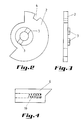
- the control member 16 comprises a disc 2 as illustrated in Figures 2 and 3.
- the disc is provided with the notch 4 and a another notch 7 both arranged on the perimeter of the disc.
- the disc is also provided with two tabs 3 arranged on one of the faces around the center.
- the legs are located opposite each other and are preferably identical which facilitates their manufacture.
- the organ also includes a bit 1 which is preferably controlled by a key (not included in the drawings).
- the bit 1 takes hold in the notch 7.
- the legs 3 each take hold in a bolt 5 and 6 which cooperate with the notches of the rod.
- the notches have a profile comprising a first inclined part and a second right side in such a way as to allow cooperation with the bolts.
- the quarter turn rotation of the bit by the key or any other type of mechanism causes a quarter turn rotation disc 2, which is placed on its course, since the bit takes taken in the notch 7.
- the disc is thus turned from a first position which corresponds to the locked mode towards a second position which corresponds to the unlocked mode.
- the movement of the bit will place the notch 4 facing the element 8 and maintain a part of all in unlocked mode.
- the first housing 12 is moved compared to the second 13.
- the bolts 5 and 6 pass along the notches 11.
- the profile of the notches and bolts is such that when the first box goes up relative to the second, the bolts are each time moved towards the control by the profile of the notches which go up.
- the bolts are incidentally mounted on springs 19 which take hold on the legs 3 to follow the movement imposed on them by the profile of notches 11.
- the toothed shape of the bolts corresponds to that of the notches 11 so that a bolt can be accommodated in a notch 11 thus making it possible to lock the bolts in the notches successive.
- the trigger 14 When the first box 12 has reached the end of the race, the trigger 14 is in the relaxed position and the element 8 takes taken in the notch 4 of the disc 2 as illustrated in FIG. 6. Thus the disc remains blocked in this position and the bolts take hold in the notches 11 of the rod.
- the user will move the first box to bring it to the desired position.
- the user takes care of course to block the first box in a position where the bolts 5 and 6 are fully engaged in a notch 11 of the rod 10.
- Push the first housing in the opposite direction is then not possible without manipulating the control member. Indeed since the bolts are engaged in the notches, the horizontal part or right of the notch 11 abuts against the horizontal part of the bolts 5 and 6 when trying to push back the first box. Locking security lock is thus ensured.
- the security lock according to the invention is in particular for locking vehicle seats. She climbed between a fixed part of the seat connected to the chassis of the vehicle and a part movable seat allowing the seat or the entire seat to be folded down seat against the steering wheel. The seat thus locked serves as an anti-theft device for the vehicle.
- the safety lock according to the invention allows effective blocking of the seat against the steering wheel.
Landscapes
- Engineering & Computer Science (AREA)
- Mechanical Engineering (AREA)
- Lock And Its Accessories (AREA)
- Burglar Alarm Systems (AREA)
- Control Of Vending Devices And Auxiliary Devices For Vending Devices (AREA)
- Casings For Electric Apparatus (AREA)
Abstract
Description
Claims (6)
- Serrure de sûreté comportant au moins une tige pourvue d'encoches dans lesquelles prend prise un pêne, ledit pêne étant monté sur un organe de commande, agencé pour dans une première position maintenir le pêne en contact avec l'encoche, caractérisée en ce que ladite tige est agencée pour être déplacée à l'intérieur d'un boítier où est également logé ledit organe de commande qui est agencé pour dans une deuxième position maintenir le pêne écarté de la tige.
- Serrure de sûreté suivant la revendication 1, caractérisée en ce que ledit organe de commande comporte un disque ayant sur une face au moins une patte qui coopère avec ledit pêne de telle façon à le maintenir en contact avec l'encoche lorsque ledit organe de commande est en première position.
- Serrure de sûreté suivant la revendication 2 caractérisée en ce que ladite patte coopère avec ledit pêne de telle façon à le maintenir écarté de la tige lorsque l'organe de commande est en deuxième position.
- Serrure de sûreté suivant l'une des revendications 1 à 3, caractérisée en ce que les encoches ont un profil comprenant une première partie inclinée et une deuxième partie droite, disposées de telle façon à coopérer avec le pêne.
- Serrure de sûreté suivant la revendication 2, caractérisée en ce que le disque comporte une autre encoche sur sa partie périphérique agencée à coopérer avec une unité de déclenchement de la tige.
- Serrure de sûreté suivant l'une des revendications 1 à 5, caractérisée en ce qu'elle est destinée à verrouiller un siège de véhicule.
Applications Claiming Priority (2)
| Application Number | Priority Date | Filing Date | Title |
|---|---|---|---|
| BE9700347A BE1011110A6 (fr) | 1997-04-15 | 1997-04-15 | Serrure de surete. |
| BE9700347 | 1997-04-15 |
Publications (2)
| Publication Number | Publication Date |
|---|---|
| EP0872391A2 true EP0872391A2 (fr) | 1998-10-21 |
| EP0872391A3 EP0872391A3 (fr) | 2000-06-07 |
Family
ID=3890469
Family Applications (1)
| Application Number | Title | Priority Date | Filing Date |
|---|---|---|---|
| EP98870083A Withdrawn EP0872391A3 (fr) | 1997-04-15 | 1998-04-15 | Serrure de sûreté |
Country Status (2)
| Country | Link |
|---|---|
| EP (1) | EP0872391A3 (fr) |
| BE (1) | BE1011110A6 (fr) |
Cited By (1)
| Publication number | Priority date | Publication date | Assignee | Title |
|---|---|---|---|---|
| WO2003101793A1 (fr) * | 2002-05-31 | 2003-12-11 | Idé-Teknik Itv Aktiebolag | Dispositif anti-vol pour vehicule, vehicule equipe d'un dispositif anti-vol et procede de mise en oeuvre d'un dispositif anti-vol dans un vehicule |
Citations (1)
| Publication number | Priority date | Publication date | Assignee | Title |
|---|---|---|---|---|
| WO1995032109A1 (fr) | 1994-05-20 | 1995-11-30 | Christian Fontaine | Dispositif antivol adapte au siege d'un vehicule |
Family Cites Families (5)
| Publication number | Priority date | Publication date | Assignee | Title |
|---|---|---|---|---|
| US1543397A (en) * | 1924-07-29 | 1925-06-23 | Yale & Towne Mfg Co | Padlock |
| US4116297A (en) * | 1977-06-03 | 1978-09-26 | Ross Curtis R | Vehicle seat lock |
| FR2698904A1 (fr) * | 1992-12-07 | 1994-06-10 | Securtir Sa | Dispositif antivol notamment pour portes arrière de véhicules de transport routier. |
| US5488844A (en) * | 1994-04-26 | 1996-02-06 | Winner International Royalty Corporation | Security device |
| US5644937A (en) * | 1996-04-30 | 1997-07-08 | Farino; Joseph | Vehicle theft prevention device |
-
1997
- 1997-04-15 BE BE9700347A patent/BE1011110A6/fr not_active IP Right Cessation
-
1998
- 1998-04-15 EP EP98870083A patent/EP0872391A3/fr not_active Withdrawn
Patent Citations (1)
| Publication number | Priority date | Publication date | Assignee | Title |
|---|---|---|---|---|
| WO1995032109A1 (fr) | 1994-05-20 | 1995-11-30 | Christian Fontaine | Dispositif antivol adapte au siege d'un vehicule |
Cited By (1)
| Publication number | Priority date | Publication date | Assignee | Title |
|---|---|---|---|---|
| WO2003101793A1 (fr) * | 2002-05-31 | 2003-12-11 | Idé-Teknik Itv Aktiebolag | Dispositif anti-vol pour vehicule, vehicule equipe d'un dispositif anti-vol et procede de mise en oeuvre d'un dispositif anti-vol dans un vehicule |
Also Published As
| Publication number | Publication date |
|---|---|
| EP0872391A3 (fr) | 2000-06-07 |
| BE1011110A6 (fr) | 1999-04-06 |
Similar Documents
| Publication | Publication Date | Title |
|---|---|---|
| EP0615879B1 (fr) | Dispositif de réglage de position de siège pour véhicule automobile | |
| FR2815528A1 (fr) | Lit a elements de barrieres articules | |
| FR2857400A1 (fr) | Verrou destine a relier deux panneaux d'une structure d'aeroplane | |
| EP0511130B1 (fr) | Barrière pivotante | |
| FR2471793A1 (fr) | Dispositif de blocage d'une extremite d'une ceinture de securite pour vehicules automobiles, combine avec une glissiere d'un siege | |
| EP3564467A1 (fr) | Système de fermeture à verrouillage mécanique | |
| FR2789108A1 (fr) | Systeme de serrure pour element de fermeture mobile | |
| EP0808783B1 (fr) | Dispositif à taquets mobiles avec rappel assisté pour l'empilage, dans toutes les positions, d'objets de relativement grandes dimensions et sensiblement plats | |
| EP1368693A1 (fr) | Paire de lunettes a mecanisme d'ouverture automatique de branche | |
| FR2836946A1 (fr) | Dispositif de double verrouillage, notamment pour portillon ou analogue de barriere de protection d'une piscine | |
| EP0161960A2 (fr) | Installation pour la consignation de chariots | |
| EP1728958A1 (fr) | Dispositif de fermeture et d'ouverture de vantail de porte ou portail | |
| EP0605473B1 (fr) | Dispositif pour le verrouillage d'un corps coulissant et, en particulier, d'une borne de voirie retractable | |
| FR2724687A1 (fr) | Dispositif de fermeture de surete, en particulier pour capot-regard | |
| EP0838372B1 (fr) | Dispositif d'aide au chargement d'un coffre de véhicule automobile | |
| EP0704387B1 (fr) | Dispositif de sécurité notamment à l'égard des enfants pour bac de collecte de déchets | |
| FR2759727A3 (fr) | Dispositif de fermeture pour porte | |
| FR2858001A1 (fr) | Serrure a pene dormant, manoeuvrable par bouton ou clef | |
| FR2540171A1 (fr) | Cadenas a elements separables par coulissement axial | |
| EP0072332A1 (fr) | Barillet de sûreté à double rotor et appareil de fermeture qui en est équipe | |
| FR2683579A1 (fr) | Agencement de verrouillage d'un organe mobile de fermeture d'une ouverture, telle qu'une porte. | |
| EP1697606B1 (fr) | Dispositif de blocage et de deblocage d'un mouvement d'actionnement, notamment pour serrure de surete, muni de moyens de blocage en cas de tronconnement du barillet | |
| FR2802565A1 (fr) | Boitier median de serrure antipanique multipoint reversible, et serrure antipanique equipee d'un tel boitier | |
| BE1011110A6 (fr) | Serrure de surete. | |
| FR2812602A1 (fr) | Ensemble de console notamment pour habitacle de vehicule automobile |
Legal Events
| Date | Code | Title | Description |
|---|---|---|---|
| PUAI | Public reference made under article 153(3) epc to a published international application that has entered the european phase |
Free format text: ORIGINAL CODE: 0009012 |
|
| AK | Designated contracting states |
Kind code of ref document: A2 Designated state(s): AT BE CH CY DE DK ES FI FR GB GR IE IT LI LU MC NL PT SE |
|
| AX | Request for extension of the european patent |
Free format text: AL;LT;LV;MK;RO;SI |
|
| PUAL | Search report despatched |
Free format text: ORIGINAL CODE: 0009013 |
|
| AK | Designated contracting states |
Kind code of ref document: A3 Designated state(s): AT BE CH CY DE DK ES FI FR GB GR IE IT LI LU MC NL PT SE |
|
| AX | Request for extension of the european patent |
Free format text: AL;LT;LV;MK;RO;SI |
|
| AKX | Designation fees paid | ||
| REG | Reference to a national code |
Ref country code: DE Ref legal event code: 8566 |
|
| STAA | Information on the status of an ep patent application or granted ep patent |
Free format text: STATUS: THE APPLICATION IS DEEMED TO BE WITHDRAWN |
|
| 18D | Application deemed to be withdrawn |
Effective date: 20001101 |