EP0872401A2 - Colonne de direction pour dispositifs de protection des passagers et direction de sécurité - Google Patents
Colonne de direction pour dispositifs de protection des passagers et direction de sécurité Download PDFInfo
- Publication number
- EP0872401A2 EP0872401A2 EP98105313A EP98105313A EP0872401A2 EP 0872401 A2 EP0872401 A2 EP 0872401A2 EP 98105313 A EP98105313 A EP 98105313A EP 98105313 A EP98105313 A EP 98105313A EP 0872401 A2 EP0872401 A2 EP 0872401A2
- Authority
- EP
- European Patent Office
- Prior art keywords
- steering column
- steering
- occupant protection
- protection device
- deformation
- Prior art date
- Legal status (The legal status is an assumption and is not a legal conclusion. Google has not performed a legal analysis and makes no representation as to the accuracy of the status listed.)
- Granted
Links
- 230000000712 assembly Effects 0.000 title 1
- 238000000429 assembly Methods 0.000 title 1
- 239000003380 propellant Substances 0.000 claims description 13
- 238000000034 method Methods 0.000 claims description 11
- 238000006073 displacement reaction Methods 0.000 claims description 7
- 238000004519 manufacturing process Methods 0.000 claims description 6
- 239000011265 semifinished product Substances 0.000 claims description 6
- 230000005540 biological transmission Effects 0.000 claims description 5
- 238000005304 joining Methods 0.000 claims description 4
- 239000000463 material Substances 0.000 claims description 4
- 230000008878 coupling Effects 0.000 claims description 3
- 238000010168 coupling process Methods 0.000 claims description 3
- 238000005859 coupling reaction Methods 0.000 claims description 3
- 230000015572 biosynthetic process Effects 0.000 claims description 2
- 230000008859 change Effects 0.000 claims description 2
- 238000004026 adhesive bonding Methods 0.000 claims 1
- 230000000149 penetrating effect Effects 0.000 claims 1
- 238000003892 spreading Methods 0.000 claims 1
- 208000027418 Wounds and injury Diseases 0.000 description 5
- 230000006378 damage Effects 0.000 description 5
- 208000014674 injury Diseases 0.000 description 5
- 230000006835 compression Effects 0.000 description 4
- 238000007906 compression Methods 0.000 description 4
- 238000010521 absorption reaction Methods 0.000 description 3
- 238000010276 construction Methods 0.000 description 3
- 230000008569 process Effects 0.000 description 3
- 238000005096 rolling process Methods 0.000 description 3
- 230000008901 benefit Effects 0.000 description 2
- 238000005516 engineering process Methods 0.000 description 2
- 238000010304 firing Methods 0.000 description 2
- 230000014759 maintenance of location Effects 0.000 description 2
- 230000003287 optical effect Effects 0.000 description 2
- 238000004904 shortening Methods 0.000 description 2
- 206010013883 Dwarfism Diseases 0.000 description 1
- 230000004308 accommodation Effects 0.000 description 1
- 230000004913 activation Effects 0.000 description 1
- 239000000853 adhesive Substances 0.000 description 1
- 230000001070 adhesive effect Effects 0.000 description 1
- 239000003990 capacitor Substances 0.000 description 1
- 230000003111 delayed effect Effects 0.000 description 1
- 238000011161 development Methods 0.000 description 1
- 230000018109 developmental process Effects 0.000 description 1
- 239000004744 fabric Substances 0.000 description 1
- 239000011888 foil Substances 0.000 description 1
- 230000006870 function Effects 0.000 description 1
- 238000009434 installation Methods 0.000 description 1
- 230000010354 integration Effects 0.000 description 1
- 230000008407 joint function Effects 0.000 description 1
- 210000003127 knee Anatomy 0.000 description 1
- 230000009467 reduction Effects 0.000 description 1
- 230000004044 response Effects 0.000 description 1
- 230000008054 signal transmission Effects 0.000 description 1
- 230000001960 triggered effect Effects 0.000 description 1
- 230000003313 weakening effect Effects 0.000 description 1
- 238000003466 welding Methods 0.000 description 1
- 238000004804 winding Methods 0.000 description 1
- 230000037303 wrinkles Effects 0.000 description 1
Images


Classifications
-
- B—PERFORMING OPERATIONS; TRANSPORTING
- B60—VEHICLES IN GENERAL
- B60R—VEHICLES, VEHICLE FITTINGS, OR VEHICLE PARTS, NOT OTHERWISE PROVIDED FOR
- B60R21/00—Arrangements or fittings on vehicles for protecting or preventing injuries to occupants or pedestrians in case of accidents or other traffic risks
- B60R21/02—Occupant safety arrangements or fittings, e.g. crash pads
- B60R21/16—Inflatable occupant restraints or confinements designed to inflate upon impact or impending impact, e.g. air bags
- B60R21/20—Arrangements for storing inflatable members in their non-use or deflated condition; Arrangement or mounting of air bag modules or components
- B60R21/203—Arrangements for storing inflatable members in their non-use or deflated condition; Arrangement or mounting of air bag modules or components in steering wheels or steering columns
- B60R21/2032—Arrangements for storing inflatable members in their non-use or deflated condition; Arrangement or mounting of air bag modules or components in steering wheels or steering columns the inflator or inflatable member not being rotatable with the steering wheel; Arrangements using the steering column or steering wheel rim for storing, supplying or evacuating the inflation gas or for storing the inflatable member
-
- B—PERFORMING OPERATIONS; TRANSPORTING
- B60—VEHICLES IN GENERAL
- B60R—VEHICLES, VEHICLE FITTINGS, OR VEHICLE PARTS, NOT OTHERWISE PROVIDED FOR
- B60R21/00—Arrangements or fittings on vehicles for protecting or preventing injuries to occupants or pedestrians in case of accidents or other traffic risks
- B60R21/02—Occupant safety arrangements or fittings, e.g. crash pads
- B60R21/16—Inflatable occupant restraints or confinements designed to inflate upon impact or impending impact, e.g. air bags
- B60R21/20—Arrangements for storing inflatable members in their non-use or deflated condition; Arrangement or mounting of air bag modules or components
- B60R21/215—Arrangements for storing inflatable members in their non-use or deflated condition; Arrangement or mounting of air bag modules or components characterised by the covers for the inflatable member
- B60R21/2165—Arrangements for storing inflatable members in their non-use or deflated condition; Arrangement or mounting of air bag modules or components characterised by the covers for the inflatable member characterised by a tear line for defining a deployment opening
- B60R21/21656—Steering wheel covers or similar cup-shaped covers
-
- B—PERFORMING OPERATIONS; TRANSPORTING
- B62—LAND VEHICLES FOR TRAVELLING OTHERWISE THAN ON RAILS
- B62D—MOTOR VEHICLES; TRAILERS
- B62D1/00—Steering controls, i.e. means for initiating a change of direction of the vehicle
- B62D1/02—Steering controls, i.e. means for initiating a change of direction of the vehicle vehicle-mounted
- B62D1/16—Steering columns
- B62D1/18—Steering columns yieldable or adjustable, e.g. tiltable
- B62D1/19—Steering columns yieldable or adjustable, e.g. tiltable incorporating energy-absorbing arrangements, e.g. by being yieldable or collapsible
- B62D1/192—Yieldable or collapsible columns
-
- B—PERFORMING OPERATIONS; TRANSPORTING
- B62—LAND VEHICLES FOR TRAVELLING OTHERWISE THAN ON RAILS
- B62D—MOTOR VEHICLES; TRAILERS
- B62D1/00—Steering controls, i.e. means for initiating a change of direction of the vehicle
- B62D1/02—Steering controls, i.e. means for initiating a change of direction of the vehicle vehicle-mounted
- B62D1/16—Steering columns
- B62D1/18—Steering columns yieldable or adjustable, e.g. tiltable
- B62D1/19—Steering columns yieldable or adjustable, e.g. tiltable incorporating energy-absorbing arrangements, e.g. by being yieldable or collapsible
- B62D1/195—Yieldable supports for the steering column
-
- B—PERFORMING OPERATIONS; TRANSPORTING
- B60—VEHICLES IN GENERAL
- B60R—VEHICLES, VEHICLE FITTINGS, OR VEHICLE PARTS, NOT OTHERWISE PROVIDED FOR
- B60R21/00—Arrangements or fittings on vehicles for protecting or preventing injuries to occupants or pedestrians in case of accidents or other traffic risks
- B60R21/02—Occupant safety arrangements or fittings, e.g. crash pads
- B60R21/16—Inflatable occupant restraints or confinements designed to inflate upon impact or impending impact, e.g. air bags
- B60R2021/161—Inflatable occupant restraints or confinements designed to inflate upon impact or impending impact, e.g. air bags characterised by additional means for controlling deployment trajectory
-
- B—PERFORMING OPERATIONS; TRANSPORTING
- B60—VEHICLES IN GENERAL
- B60R—VEHICLES, VEHICLE FITTINGS, OR VEHICLE PARTS, NOT OTHERWISE PROVIDED FOR
- B60R21/00—Arrangements or fittings on vehicles for protecting or preventing injuries to occupants or pedestrians in case of accidents or other traffic risks
- B60R21/02—Occupant safety arrangements or fittings, e.g. crash pads
- B60R21/16—Inflatable occupant restraints or confinements designed to inflate upon impact or impending impact, e.g. air bags
- B60R21/23—Inflatable members
- B60R21/231—Inflatable members characterised by their shape, construction or spatial configuration
- B60R2021/23169—Inflatable members characterised by their shape, construction or spatial configuration specially adapted for knee protection
-
- B—PERFORMING OPERATIONS; TRANSPORTING
- B60—VEHICLES IN GENERAL
- B60R—VEHICLES, VEHICLE FITTINGS, OR VEHICLE PARTS, NOT OTHERWISE PROVIDED FOR
- B60R21/00—Arrangements or fittings on vehicles for protecting or preventing injuries to occupants or pedestrians in case of accidents or other traffic risks
- B60R21/02—Occupant safety arrangements or fittings, e.g. crash pads
- B60R21/16—Inflatable occupant restraints or confinements designed to inflate upon impact or impending impact, e.g. air bags
- B60R21/26—Inflatable occupant restraints or confinements designed to inflate upon impact or impending impact, e.g. air bags characterised by the inflation fluid source or means to control inflation fluid flow
- B60R21/263—Inflatable occupant restraints or confinements designed to inflate upon impact or impending impact, e.g. air bags characterised by the inflation fluid source or means to control inflation fluid flow using a variable source, e.g. plural stage or controlled output
- B60R2021/2633—Inflatable occupant restraints or confinements designed to inflate upon impact or impending impact, e.g. air bags characterised by the inflation fluid source or means to control inflation fluid flow using a variable source, e.g. plural stage or controlled output with a plurality of inflation levels
Definitions
- the invention relates to a steering column for a vehicle according to the preamble of the claim 1 as well as occupant protection devices, safety steering systems and steering wheels, in which or for which such steering columns are preferably used. Furthermore, the Invention also method for manufacturing the steering column.
- the invention has for its object to provide steering columns with which the Risk of injury to vehicle occupants can be reduced even further.
- each of the Connection profiles assigned at least one deformation element.
- deformability are these deformation elements in relation to an expected exposure to Accident force carried out so that they either alone the required for safety reasons Allow shortening of the steering column or in addition to conventional ones Upsetting devices are effective.
- Another key feature is between these at least two deformation members an essentially dimensionally stable steering column intermediate section intended. Dimensionally stable in this context means that the No significant loads to be expected during a vehicle accident Deformations occur. The changes in length of this steering column section when acted upon with compressive force are so low that they can, for example, a maximum of 5% of the total compression turn off.
- the Steering column material itself makes contributions to energy absorption and thus guarantees relatively gentle approach of the vehicle occupant to the response threshold of the force limiter, which opposite a steering column receptacle which rotatably supports the steering column supports the vehicle body.
- these deformation elements take over Joint functions.
- the deformation member facing the steering column gear able to cope with the tilting movement of the to reduce the entire steering column in such a way that hardly any upward movement of the Steering wheel is lockable.
- this then ensures the steering wheel facing deformation element for that, in particular in so-called seat giants or Seat dwarfs can do an energy-absorbing shift of the steering wheel, though this is at an unfavorable angle of attack relative to the vehicle occupant.
- part of the steering wheel itself available energy absorption capacity in the deformation element can be relocated. Accordingly, the steering wheel itself would not have to be a three or Four-spoke steering wheel are executed, but is also available as a two-spoke steering wheel representable. This results in additional lightweight construction potential for a steering arrangement, in which the steering column according to the invention is used.
- Another significant advantage can be seen in the fact that one is preferably a tubular body executed steering column parts of an airbag device directly into the steering column can be relocated.
- the steering column is at the same time housing for at least a gas generator with diffuser and gas cushion.
- a division is also conceivable in such a way that, for example, the generators are only arranged within the steering column while the gas cushion to be filled by them is inside the steering wheel hub is stowed.
- snap locks are conceivable as described for example in WO 97/01460 (B 60R 21/16).
- the gas generator is not held by the steering wheel hub, but directly inside the Steering column housed in the intermediate section of the steering column.
- the gas generator housing is an integral part of a is cylindrical jacket, the steering column intermediate section in the sense of the invention forms.
- the inner wall of the steering column intermediate section is therefore simultaneous Housing wall for one or more generators.
- the outer wall is opposite Bearing seat for pivot bearings built into a steering column mount.
- ring lighters that activate of the propellant charges accommodated in the gas generators regardless of the enable the respective angle of rotation of the steering wheel.
- a ring lighter elements can be used, such as those used in weapon technology are known.
- the ring lighter can either on the outside of the steering column intermediate section be arranged or be integrated in the wall.
- the Ignition energy can be triggered mechanically and / or electromagnetically be introduced into the propellant charge.
- the tubular body is designed as a hydroformed or hydroformed molded part of paramount importance. All connection profiles, so for example adapter sections to a lower part of the steering column facing the steering gear or towards the steering wheel itself, are molded directly onto the steering column. In this context, the direct formation of a notch is also proposed or a locking cam, in which, for example, an actuable by a steering wheel lock Locking cam can be moved into it.
- the tubular body can also be produced by rolling.
- a preferred one Manufacturing process provides that, for example, in a tubular semi-finished product First, a kit consisting of a gas generator and diffuser is housed. Roll forming then creates a bellows or corrugated tube-like structure at the two free ends Rolled profile in such a way that at the same time a fixation of the kit he follows.
- the assembly produced in this way can now additionally by at least a gas cushion can be expanded or can be combined with a steering wheel, which in turn already has a gas cushion ready.
- the configuration of at least one of the deformation elements is of particular importance as a damper for influencing the speed of propagation of the gas cushion.
- the gas cushion folds into depressions in the deformation element deliberately placed inside. This is how the gas cushion unfolds in the initial stage due to friction defines delayed, so that the vehicle occupant despite rapid deployment sufficient retention gas volume is not exaggeratedly hard as that as a retention element effective gas cushion is shot.
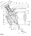
- FIG. 1 shows a steering column, generally designated 1, with a first one Connection profile 2, on which a steering wheel 3 preferably with a snap lock is arranged, and with a second connection profile 4, which is angular in cross section is and a correspondingly designed coupling piece 5 of a lower steering column part 6.
- the steering column lower part 6 inserted into the connecting profile 4 is in two parts here executed and has a first compression area 7, which in a frontal impact Contributes to the shortening of the entire steering column 1 when using an articulated rod 8 and a gimbal joint 9 due to deformation in the front end high axial loads are generated.
- Further compression areas 10 and 11 are realized by means of deformation elements 12 and 13, which here are formed like bellows or corrugated tubes are.
- the gas cushion 14 is here inflatable by at least one of the two gas generators 15, 16, which are in one Steering column intermediate section 17 are located.
- Each of the gas generators 15, 16 is with ring lighters 18, 19 equipped with triggers like firing pin devices 20, 21 (impact body which can be driven by a small propellant charge, preferably designed as a bolt) can be activated at the instigation of a control device 22.
- the firing pin devices 20, 21 are fastened to a steering column receptacle 23, in which a rotary bearing 24, 25 the steering column 1 is rotatably mounted.
- the steering column 1 is one Force limiter 26 can be supported on the vehicle body 27 shown symbolically.
- the force-displacement identifier of the force limiter 26 is in the illustrated embodiment Influenced by a throttle valve 28, which can also be acted upon by the control unit 22 is.
- the steering column 1 is thus part of an occupant protection device in which the safety contributions made by the steering column 1 alone further measures are provided to reduce the risk of injury to the vehicle occupants.
- For influencing the force-displacement identifier of the force limiter 26 can be different Parameters can be taken into account individually or in combination.
- One designated with 29 Sensor symbol represents a sensor system with the following parameters, for example The following can be recorded: occupant weight, position of a driver's seat, not shown here, Backrest inclination of the driver's seat, timing in the event of an accident-related vehicle deceleration, Accidental deformation of the vehicle body depending on the collision location and / or the impact intensity, number of impact fittings on the vehicle, Filling behavior of the gas cushion 14.
- the deformation member 12 is also at the same time Gas cushion receptacle.
- One arranged in front of the wave profile of the deformation element 14 Fastening ring 33 ensures that even when the pressure is fully applied Gas cushion 14 this can not detach from the steering column 1.
- the gas generator 15 is toroidal in this case, so that it also flows out of the diffuser 30 Gas can get into the gas cushion 14.
- the diffuser 30 can also face the compression area 7 be, then via outlet openings (not shown here) in the deformation member 13 for example to be able to fill a footwell or knee airbag.
- the activation of the gas generators does not necessarily have to be by mechanical means of ring lighters, but can also be done for example by electromagnetic Ignition energy is transmitted.
- the Introducing the ignition described here from the non-rotatable steering column receptacle 23 out makes it possible to dispense with the previously used coil springs.
- the assembly of the in Figure 1 shown steering column assembly is facilitated because only in the installed position fixed components are to be wired together.
- this tubular body designed steering column 1 receptacle for the gas cushion 14 and the gas generators 15, 16 is.
- this tubular body is a component produced by internal high pressure forming, on which all for the invention Function of the steering column 1 important component sections directly from the same material are molded. This applies in particular to the lower part of the steering column 6 and the steering wheel 3 assigned adapter sections, but also for the shape of the deformation members 12 yourself. Since geometries can be varied within wide limits with hydroforming, a deformation behavior can be achieved by selecting the right wall thickness and specifying cross sections be adjusted to best suit the various accident situations becomes.
- Wall thickness and / or geometry variations can be used for the deformation elements 12 and 13 also different force-displacement identifiers can be selected, for example by choosing different diameters.
- the manufacture of the steering column 1 can also be carried out Roles should be considered.
- an in Figure 2 shown semifinished product 1 ' which is composed of pipe sections 12', 13 'and 17' that have different wall thicknesses.
- the different wall thicknesses can be the result of a forming process on a tubular rod-shaped semi-finished product or stem from the use of pipe sections that differ in the initial state Have wall thicknesses and then for example by friction welding or other joining techniques have been put together.
- the integration of at least one gas generator including diffuser is also possible proposed in a semi-finished smooth-walled interior. The axial fixation this gas generator is then made by rolling the free ends. One for generation the deforming member contour necessary rolling process can thus at the same time for attachment of the gas generator can be used.
- the individual kits or individual elements of the Kits can also be composed of different materials.
- Housing elements 34, 35 for the ring lighter 18, 19 can be retrofitted attachable attachment parts or also be designed as integral parts.
- the housing of the gas generators 15, 16 do not necessarily have to be used as inserts for Pipes are executed.
- the use of the intermediate steering column section is also conceivable 17 directly as a housing part.
- FIG. 3 Of particular importance in the embodiment shown in FIG. 3 is an in a steering wheel hub 3.3 embedded and dimensionally stable cover cap 32 ', wherein the steering wheel 3 ', for example, in analogy to the airbag device described in WO 97/01460 can be placed on the steering column 1 ''.
- the design of the Steering wheel 3 ' can also be implemented on conventionally designed steering columns. Deviating from the cover principles that have been customary up to now, cover 32 'is not here articulated on the surface of the steering wheel hub 3.3, but has been moved inwards.
- a Articulation point 36 is inward of the hub, for example in a base region of a gas generator housing attached within a guide 15 '.
- the unfolding gas cushion 14 can then move the cover 32 'only so far that it is not out of the Contour of the steering wheel 3 'emerges. A driver who may be very close to the steering wheel cannot be injured by the opening movement of the cap. This state of opening is shown in Figure 3 with dashed lines.
- the attachment point 36 in a gas generator pot 37 the is simultaneously designed as a connecting part corresponding to the steering column 1 '' move a predetermined distance ⁇ s forward. It is expressly pointed out here that it is only a schematic representation of the principle in Figure 3.
- the articulation of the cover 32 'and also its specific configuration can be wide can be varied.
- the attachment point 36 does not necessarily have to be in the Steering column 1 '' must be installed.
- the The cover 32 ' is also attached to the steering wheel hub independently of the gas generator yourself.
- the cover 32 'itself or the particular way in which it is articulated on the steering wheel hub or on the steering column 1 '' can also be designed to absorb energy be so as to allow a controlled deployment of the gas cushion 14.
- a symbolically indicated ignition lock 38 with a control cam 39 shows that a Steering column 1 '' designed according to the invention is also equipped with a steering wheel lock can be.
- a tension spring 40 is in the open position movable locking body designed as a clamping body 41 over the control cam 39 movable into a recess 42, which is here by internal high pressure forming has been introduced directly into the steering column 1 '.
- a recess simple bores or perforations are provided.
- Ignition lock principle shown can also locking elements in the region of the lower part of the steering column 6 (see Figure 1) are provided, which are then, for example, by electrical actuatable actuators are movable in the closed or open position.
- FIG. 4 relates to an occupant protection device whose An integral part of an actuator is an electrical consumer -
- a horn 43 - is switchable.
- One acts as a movement generator on pressure springs 44 parked pressure plate 45, which here via a thin rod 46, which with a weakening or buckling area in the event of an accident-related overload 46a is provided, the displacement of an annular permanent magnet 47 enables.
- the position shift of the magnet which can be carried out according to double arrow 48 47 is sensed by a ring coil 49 which is assigned to the steering column receptacle 23.
- a control signal generated in this way is then processed in the control unit 22 and used to actuate the horn 43.
- control signal would be for example a dielectric that can be moved by the pressure plate 45 between capacitor plates to convey, which are associated with the steering column receptacle 23.
- a movement generator So-called horn foils can also be used.
- the steering wheel 3 ′′ has a flange surface 50 with locking recesses in the area of the hub 3.3 51, 52 on, in the molded for steering torque transmission on the connector 2 Engage locking pins 53, 54.
- the connection between the flange surface 50 and the Connection profile takes place here via an adhesive or screw connection, not shown. It is important in this context to implement the coupling from hub 3.3 and Steering column 1 '' as a modular system.
- a consistently trained hub body with uniform airbag installations as well as uniform connection dimensions and connection geometries can be foamed in very different ways depending on the customer or vehicle. With the same Technology can thus be highly variable with different optical appearances for the interface Human-vehicle important steering wheel 3 '' are generated.
- FIGS. 5 and 6 apparent integral cap 55 proposed that by means of a predetermined tear seam 56 from a Hub cover 57 can be removed, similar to instrument panels (see. see, for example, DE-A-43 06 149, US-A-5,072,967 or US-A-5,350,191).
- instrument panels see, for example, DE-A-43 06 149, US-A-5,072,967 or US-A-5,350,191).
- Bearing arrangement 58 e.g. swivel joint, film hinge or the like.
- the integral cap can also be made in several parts, so that, for example, two flap parts hinged inwards together, one Clear the opening.
- the concepts shown in Figures 3, 5 and 6 are particular also in connection with the accommodation of airbag components within the Steering column 1 interesting, because the displacement of these components on the inside volume to be absorbed by the belongings becomes smaller. This allows the hubs themselves and consequently, covers for the gas cushion 14 are made smaller. Also through this measure becomes the risk of injury arising from the opening cover, reduced.
- Steering columns are not limited to the embodiments shown in the drawing, but can be combined in different ways. It must be taken into account that individual elements of the inventive variants presented here also in combination with conventional steering systems or their components already make significant contributions to Minimizing the risk of injury.
Landscapes
- Engineering & Computer Science (AREA)
- Mechanical Engineering (AREA)
- Chemical & Material Sciences (AREA)
- Combustion & Propulsion (AREA)
- Transportation (AREA)
- Air Bags (AREA)
- Steering Controls (AREA)
Priority Applications (5)
| Application Number | Priority Date | Filing Date | Title |
|---|---|---|---|
| DE29824725U DE29824725U1 (de) | 1997-04-16 | 1998-03-24 | Insassenschutzeinrichtung für ein Fahrzeug |
| DE29824722U DE29824722U1 (de) | 1997-04-16 | 1998-03-24 | Lenksäule für ein Fahrzeug |
| DE29824724U DE29824724U1 (de) | 1997-04-16 | 1998-03-24 | Insassenschutzeinrichtung für ein Fahrzeug |
| DE29824726U DE29824726U1 (de) | 1997-04-16 | 1998-03-24 | Sicherheitslenkung für ein Fahrzeug |
| DE29824723U DE29824723U1 (de) | 1997-04-16 | 1998-03-24 | Insassenschutzeinrichtung für ein Fahrzeug |
Applications Claiming Priority (2)
| Application Number | Priority Date | Filing Date | Title |
|---|---|---|---|
| DE19715883 | 1997-04-16 | ||
| DE19715883 | 1997-04-16 |
Publications (3)
| Publication Number | Publication Date |
|---|---|
| EP0872401A2 true EP0872401A2 (fr) | 1998-10-21 |
| EP0872401A3 EP0872401A3 (fr) | 2002-04-17 |
| EP0872401B1 EP0872401B1 (fr) | 2003-10-01 |
Family
ID=7826691
Family Applications (1)
| Application Number | Title | Priority Date | Filing Date |
|---|---|---|---|
| EP98105313A Expired - Lifetime EP0872401B1 (fr) | 1997-04-16 | 1998-03-24 | Colonne de direction pour dispositifs de protection des passagers et direction de sécurité |
Country Status (4)
| Country | Link |
|---|---|
| US (1) | US6189919B1 (fr) |
| EP (1) | EP0872401B1 (fr) |
| DE (1) | DE59809761D1 (fr) |
| ES (1) | ES2207763T3 (fr) |
Cited By (7)
| Publication number | Priority date | Publication date | Assignee | Title |
|---|---|---|---|---|
| WO2000074981A1 (fr) * | 1999-06-08 | 2000-12-14 | Takata-Petri Ag | Module d'airbag pour volants |
| WO2001021450A1 (fr) * | 1999-09-17 | 2001-03-29 | Volkswagen Aktiengesellschaft | Systeme de coussin gonflable situe sur le volant d'un vehicule |
| EP1344708A2 (fr) | 2002-03-14 | 2003-09-17 | ThyssenKrupp Presta AG | Arbre de direction de colonne de direction pour un véhicule automobile |
| US6896290B2 (en) | 2002-03-14 | 2005-05-24 | Thyssenkrupp Presta Aktiengessellschaft | Steering gear shaft for a steering column of a motor vehicle |
| US6908109B2 (en) | 2002-03-14 | 2005-06-21 | Thyssenkrupp Presta Aktiengesellschaft | Steering gear shaft for a steering column of a motor vehicle |
| WO2007002970A1 (fr) * | 2005-06-30 | 2007-01-11 | Inventus Engineering Gmbh | Colonne de direction pourvue d'un dispositif d'absorption de l'energie de collision |
| DE10064250B4 (de) * | 2000-02-26 | 2013-12-24 | Volkswagen Ag | Einrichtung mit einer axial deformierbaren Lenksäule eines Kraftfahrzeugs |
Families Citing this family (26)
| Publication number | Priority date | Publication date | Assignee | Title |
|---|---|---|---|---|
| KR20000068364A (ko) * | 1997-07-03 | 2000-11-25 | 후루까와 준노스께 | 분리형 트랜스포머 및 분리형 트랜스포머를 이용한전송제어장치 |
| US6512437B2 (en) * | 1997-07-03 | 2003-01-28 | The Furukawa Electric Co., Ltd. | Isolation transformer |
| US7314234B2 (en) * | 1998-05-11 | 2008-01-01 | Thyssenkrupp Presta Ag | Steering column and adjustment method for a steering column |
| US7080855B2 (en) * | 1998-05-11 | 2006-07-25 | Thyssenkrupp Presta Ag | Safety steering column, motor vehicle with a safety system and safety method |
| JP2000283139A (ja) * | 1999-03-30 | 2000-10-13 | Fuji Heavy Ind Ltd | 車両用プロペラシャフト |
| FR2801269B1 (fr) * | 1999-11-19 | 2002-02-08 | Nacam | Dispositif d'absorption d'energie modulaire a charges pyrotechniques d'une colonne de direction de vehicule automobile |
| DE10001420A1 (de) * | 2000-01-15 | 2001-07-19 | Schenck Ag Carl | Passives Kraftelement auf Basis elektrorheologischer Flüssigkeiten |
| US20050156424A1 (en) * | 2000-02-29 | 2005-07-21 | Thyssenkrupp Presta Ag | Steering column and manufacturing method thereof |
| US6726248B2 (en) * | 2000-05-16 | 2004-04-27 | Nsk Ltd. | Impact absorbing type steering column apparatus |
| SE518451C2 (sv) * | 2000-07-03 | 2002-10-08 | Saab Automobile | Rattarrangemang för ett motorfordon |
| US20020048371A1 (en) * | 2000-10-24 | 2002-04-25 | Ryuichi Iwamura | Method and system for secure digital decoder with secure key distribution |
| US6655804B2 (en) * | 2001-06-29 | 2003-12-02 | Daniel G. Streibig | Colored contact lens and method of making same |
| JP2003118595A (ja) * | 2001-08-06 | 2003-04-23 | Nsk Ltd | 車両用ステアリング装置及びその製造方法 |
| WO2003033328A2 (fr) * | 2001-10-16 | 2003-04-24 | Delphi Technologies, Inc. | Systeme reactif a absorption d'energie pour colonnes de direction |
| US20070132221A1 (en) * | 2005-12-13 | 2007-06-14 | Lear Corporation | Energy absorbing fill tube for a side car curtain system |
| JP4838073B2 (ja) * | 2006-08-25 | 2011-12-14 | 株式会社東海理化電機製作所 | 磁気式位置検出装置の磁石保持構造及びステアリングロック装置 |
| DE102007026378A1 (de) | 2007-05-21 | 2008-11-27 | Fludicon Gmbh | Schwingungsdämpfer |
| ITMO20120125A1 (it) * | 2012-05-11 | 2013-11-12 | Cnh Italia Spa | Dispositivo di sterzatura per un veicolo. |
| EP2923900B1 (fr) * | 2012-11-26 | 2017-05-24 | NSK Ltd. | Dispositif de direction |
| DE102013003841B4 (de) | 2012-12-21 | 2016-11-24 | Fludicon Gmbh | Schwingungsdämpfer |
| DE102015213576A1 (de) * | 2015-05-11 | 2016-11-17 | Robert Bosch Gmbh | Verfahren zur Ansteuerung von Rückhaltemitteln für ein Fahrzeug, Computerprogramm, elektronisches Speichermedium und Vorrichtung Ansteuerung von Rückhaltemitteln für ein Fahrzeug |
| US10518732B2 (en) * | 2017-08-04 | 2019-12-31 | Byton Limited | Airbag devices designed to utilize a reduced interior surface area of a vehicle |
| US10583855B2 (en) | 2017-09-05 | 2020-03-10 | Byton Gmbh | Steering device for a vehicle, in particular an electric vehicle |
| US20200224760A1 (en) * | 2019-01-10 | 2020-07-16 | GM Global Technology Operations LLC | Vehicle including a knit element connecting a first vehicle member to a second vehicle member |
| US11407436B2 (en) | 2019-03-04 | 2022-08-09 | Byton North America Corporation | Steering wheel with fixed center |
| DE102019107577A1 (de) * | 2019-03-25 | 2020-10-01 | Zf Automotive Germany Gmbh | Steer-by-Wire Lenksystem |
Citations (6)
| Publication number | Priority date | Publication date | Assignee | Title |
|---|---|---|---|---|
| US5072967A (en) | 1990-07-12 | 1991-12-17 | Davidson Textron Inc. | Instrument panel with invisible airbag deployment door |
| DE4118227A1 (de) | 1990-06-13 | 1991-12-19 | Volkswagen Ag | Befestigungsanordnung fuer eine sicherheitslenksaeule in einem pkw |
| DE4306149A1 (de) | 1993-02-27 | 1994-09-01 | Opel Adam Ag | Abdeckung für die Öffnung eines einen Airbag aufnehmenden Raumes |
| US5350191A (en) | 1992-03-25 | 1994-09-27 | Takata Corporation | Lid of an air bag device for a passenger |
| DE19508443A1 (de) | 1994-03-18 | 1995-09-21 | Volkswagen Ag | Halterung für einen lenkradseitigen Lenksäulenteil |
| WO1997001460A1 (fr) | 1995-06-26 | 1997-01-16 | Alliedsignal Inc. | Volant encliquetable et amovible a logement de coussin glonflableintegre |
Family Cites Families (78)
| Publication number | Priority date | Publication date | Assignee | Title |
|---|---|---|---|---|
| US3434367A (en) * | 1967-09-01 | 1969-03-25 | Chrysler Corp | Steering column |
| DE2150061C3 (de) * | 1971-10-07 | 1975-08-07 | Adam Opel Ag, 6090 Ruesselsheim | Aus Blech bestehendes, plastisch verformbares Deformationsglied für Sicherheitslenkungen von Kraftfahrzeugen |
| JPS4845877A (fr) * | 1971-10-15 | 1973-06-30 | ||
| DE2212713C3 (de) * | 1972-03-16 | 1985-08-29 | Adam Opel AG, 6090 Rüsselsheim | Sicherheitslenksäule für Fahrzeuge, insbesondere Kraftfahrzeuge |
| US3832911A (en) * | 1972-12-04 | 1974-09-03 | Ford Motor Co | Energy absorbing steering column |
| US3805636A (en) * | 1972-12-04 | 1974-04-23 | Ford Motor Co | Energy absorbing steering column for motor vehicles |
| JPS5213701Y2 (fr) * | 1973-12-03 | 1977-03-28 | ||
| JPS5294636U (fr) * | 1976-01-13 | 1977-07-15 | ||
| DE3021808C2 (de) * | 1980-06-11 | 1982-06-16 | Bayerische Motoren Werke AG, 8000 München | Sicherheitslenkspindel für Kraftfahrzeuge |
| JPS58142509A (ja) * | 1982-02-19 | 1983-08-24 | Hitachi Ltd | 回転部分を有する自動車部品への電源供給装置 |
| US4531619A (en) * | 1982-09-24 | 1985-07-30 | Eckels Robert E | Collapsible steering column |
| GB2200488A (en) * | 1987-01-31 | 1988-08-03 | Ford Motor Co | A steering column arrangement in a motor vehicle |
| US4886295A (en) * | 1988-12-05 | 1989-12-12 | General Motors Corporation | Vehicle occupant protection system |
| US4867003A (en) * | 1988-12-19 | 1989-09-19 | General Motors Corporation | Energy absorbing steering column |
| US5205790A (en) * | 1989-05-22 | 1993-04-27 | Ecia | Steering-wheel shaft forming an anti-theft lock element |
| US5088768A (en) * | 1989-06-27 | 1992-02-18 | Fuji Kiko Company, Limited | Structure of impact absorbing steering apparatus |
| US5026092A (en) * | 1989-11-15 | 1991-06-25 | Ford Motor Company | Energy absorbing steering column assembly having a passive restraint load limiting support system |
| DE4030405C2 (de) * | 1990-09-26 | 1994-01-27 | Porsche Ag | Verstellbare Sicherheitslenksäule für ein Kraftfahrzeug |
| JPH04151348A (ja) * | 1990-10-15 | 1992-05-25 | Ashimori Ind Co Ltd | エアーバッグ収納用カバー |
| DE4120222A1 (de) * | 1991-06-19 | 1992-12-24 | Porsche Ag | Deformationsglied fuer kraftfahrzeuge |
| US5115691A (en) * | 1991-09-03 | 1992-05-26 | General Motors Corporation | Collapsible shaft assembly |
| JP2776102B2 (ja) * | 1991-12-11 | 1998-07-16 | 日産自動車株式会社 | 車両用安全装置 |
| JPH0575057U (ja) * | 1992-03-13 | 1993-10-12 | 日本精工株式会社 | 衝撃吸収式ステアリングコラム装置 |
| DK0572821T3 (da) * | 1992-06-03 | 1996-03-18 | Reiche Gmbh & Co Kg Automotive | Ratstamme |
| US5351977A (en) * | 1992-11-03 | 1994-10-04 | Trw Inc. | Externally vented airbag assembly |
| WO1994011230A1 (fr) * | 1992-11-13 | 1994-05-26 | Kabushiki Kaisha Tokai-Rika-Denki-Seisakusho | Structure de bloc de commande d'avertisseur sonore pour volant |
| US5505483A (en) * | 1993-04-28 | 1996-04-09 | Nippondenso Co., Ltd. | Airbag safety module for vehicle |
| US5290059A (en) * | 1993-04-28 | 1994-03-01 | Morton International, Inc. | Air bag module with a center mounted tubular inflator |
| GB2282574B (en) * | 1993-10-05 | 1997-01-15 | Autoliv Dev | A steering wheel |
| DE4404816B4 (de) * | 1994-02-16 | 2005-08-25 | Siemens Restraint Systems Gmbh | Vorrichtung zur Übertragung von Energie und Daten zwischen der Fahrzeug- und der Lenkradseite von Kraftfahrzeugen |
| FR2716857B1 (fr) * | 1994-03-03 | 1997-07-18 | Autoliv Dev | Volant avec dispositif de protection anti-choc à sac gonflable prémonté. |
| US5626360A (en) * | 1994-03-14 | 1997-05-06 | Morton International, Inc. | Linear igniters for airbag inflators |
| JPH07257400A (ja) * | 1994-03-25 | 1995-10-09 | Nippon Seiko Kk | 衝撃吸収式ステアリングコラム装置用エネルギ吸収部材 |
| DE4418628A1 (de) * | 1994-05-27 | 1995-11-30 | Trw Repa Gmbh | Insassen-Rückhaltesystem für die Fahrerseite in einem Fahrzeug |
| DE4423963A1 (de) * | 1994-07-07 | 1996-01-11 | Trw Repa Gmbh | Fahrzeuglenkrad für die Bestückung mit einem integrierten Gassack-Rückhaltesystem |
| US5609356A (en) * | 1995-01-11 | 1997-03-11 | Morton International, Inc. | Cylindrical air bag module assembly |
| JPH08230594A (ja) * | 1995-02-24 | 1996-09-10 | Nippon Seiko Kk | 運転席用エアバッグモジュール |
| EP0728652B1 (fr) * | 1995-02-27 | 2003-05-14 | Toyoda Gosei Co., Ltd. | Procédé de fabrication d'un volant de direction et volant obtenu par ce procédé |
| DE19509165A1 (de) * | 1995-03-14 | 1996-09-19 | Mst Automotive Gmbh | Gassack-Aufprallschutz-System |
| KR960033968A (ko) * | 1995-03-22 | 1996-10-22 | 배순훈 | 자동차의 충격완화용 압축식 핸들 |
| DE19510418A1 (de) * | 1995-03-24 | 1996-09-26 | Mst Automotive Gmbh | Sicherheitslenkrad |
| JPH08282425A (ja) * | 1995-04-20 | 1996-10-29 | Honda Motor Co Ltd | エアバッグ装置 |
| EP0739786B2 (fr) * | 1995-04-27 | 2003-05-21 | Toyoda Gosei Co., Ltd. | Volant incorporant un module à coussin d'air |
| US5722686A (en) * | 1995-05-16 | 1998-03-03 | Trw Vehicle Safety Systems, Inc. | Method and apparatus for sensing an occupant position using capacitance sensing |
| DE19525928C2 (de) | 1995-07-04 | 1997-07-17 | Petri Ag | Vorrichtung zur Übertragung elektrischer Signale |
| US5630611A (en) * | 1995-07-21 | 1997-05-20 | Textron Inc. | Mounting assembly for air bag |
| US5599039A (en) * | 1995-07-21 | 1997-02-04 | Textron Inc. | Spring retainer air bag mounting device |
| JP3651068B2 (ja) * | 1995-07-31 | 2005-05-25 | 豊田合成株式会社 | エアバッグ装置 |
| DE19530589A1 (de) | 1995-08-19 | 1997-02-20 | Bosch Gmbh Robert | Anordnung zum kontaktlosen Übertragen eines Airbag-Auslösesignals |
| DE19532043C2 (de) * | 1995-08-31 | 2002-10-24 | Marquardt Gmbh | Lenkrad für ein Kraftfahrzeug |
| US5503426A (en) * | 1995-09-01 | 1996-04-02 | Morton International, Inc. | Method of attaching a mounting bracket to an airbag inflator |
| DE19532296A1 (de) | 1995-09-01 | 1997-03-06 | Bosch Gmbh Robert | Anordnung zum kontaktlosen Übertragen von Signalen zwischen zwei gegeneinander drehbar gelagerten Fahrzeugteilen |
| DE29514314U1 (de) * | 1995-09-06 | 1995-10-26 | HS Technik und Design Technische Entwicklungen GmbH, 82234 Weßling | Lenkvorrichtung für ein Kraftfahrzeug |
| US5584501A (en) * | 1995-09-15 | 1996-12-17 | Trw Inc. | Vehicle occupant restraint apparatus |
| DE19537628A1 (de) | 1995-10-10 | 1997-04-17 | Mst Automotive Gmbh | Vorrichtung zum Übertragen von Signalen |
| DE29516625U1 (de) | 1995-10-20 | 1996-01-25 | Trw Occupant Restraint Systems Gmbh, 73551 Alfdorf | Lenkwelle für ein Fahrzeug mit einem Gassack-Rückhaltesystem |
| DE29516621U1 (de) | 1995-10-20 | 1996-01-25 | Trw Occupant Restraint Systems Gmbh, 73551 Alfdorf | Baugruppe aus einem Lenkrad, einer Lenkwelle sowie einem Gasgenerator |
| DE19541998B4 (de) | 1995-11-10 | 2006-08-03 | Robert Bosch Gmbh | Airbagsystem für ein Kraftfahrzeug |
| US5617763A (en) * | 1995-11-24 | 1997-04-08 | General Motors Corporation | Steering wheel for motor vehicle |
| US5765860A (en) * | 1996-02-16 | 1998-06-16 | Autoliv Asp, Inc. | Apparatus for mounting an inflatable vehicle occupant restraint module to a vehicle steering wheel |
| DE19609266C2 (de) | 1996-02-27 | 1999-06-10 | Petri Ag | Verfahren und Vorrichtung zur berührungslosen Übertragung elektrischer Energie und von Daten in Kraftfahrzeugen |
| DE19643451A1 (de) | 1996-02-27 | 1997-08-28 | Petri Ag | Verfahren und Vorrichtung zur berührungslosen Übertragung elektrischer Energie und von Daten in Kraftfahrzeugen |
| DE29606830U1 (de) * | 1996-04-15 | 1996-08-08 | Trw Occupant Restraint Systems Gmbh, 73551 Alfdorf | Baugruppe aus einem Lenkrad, einer Lenkwelle und einem Gassack-Modul |
| US5893580A (en) * | 1996-05-22 | 1999-04-13 | Hoagland; Larry D. | Motor vehicle steering column safety device |
| US5806883A (en) * | 1996-07-26 | 1998-09-15 | Trw Inc. | Steering wheel and air bag module |
| DE29614586U1 (de) | 1996-08-22 | 1996-12-19 | Trw Occupant Restraint Systems Gmbh, 73551 Alfdorf | Lenkrad mit einem Gassack-Rückhaltesystem |
| US5870930A (en) * | 1996-09-03 | 1999-02-16 | Means Industries | Steering column assembly |
| DE29616909U1 (de) | 1996-09-27 | 1997-02-06 | Trw Occupant Restraint Systems Gmbh, 73551 Alfdorf | Mit Schnapp-Verbindung arretierbare Gassack-Abdeckung |
| DE29616914U1 (de) | 1996-09-27 | 1997-01-30 | Trw Occupant Restraint Systems Gmbh, 73551 Alfdorf | Einrichtung zum Befestigen einer Gassack-Abdeckung |
| DE29617721U1 (de) | 1996-10-11 | 1997-02-06 | Trw Occupant Restraint Systems Gmbh, 73551 Alfdorf | Gassack-Abdeckung für ein Fahrzeuginsassen-Rückhaltesystem |
| US5755458A (en) * | 1996-12-11 | 1998-05-26 | Textron Inc. | Slide-in and snap-fit air bag mounting arrangement |
| DE29620375U1 (de) * | 1996-11-22 | 1997-03-20 | Trw Occupant Restraint Systems Gmbh, 73551 Alfdorf | Befestigungsvorrichtung zur Arretierung eines Fahrzeuglenkrades an einer Lenkwelle |
| DE29621295U1 (de) | 1996-11-27 | 1997-02-06 | Petri Ag, 63743 Aschaffenburg | Vorrichtung zur Befestigung eines Airbagmoduls im Lenkrad |
| KR20000057618A (ko) * | 1996-12-21 | 2000-09-25 | 볼프강 후텐로커 | 자동차용 스티어링 휠 장착형 구속 시스템 |
| US5871228A (en) * | 1997-01-21 | 1999-02-16 | Autoliv Asp, Inc. | Airbag module with sized inflator |
| DE29702441U1 (de) | 1997-02-12 | 1997-06-12 | Trw Occupant Restraint Systems Gmbh, 73551 Alfdorf | Fahrerseitige Insassen-Rückhalteeinrichtung |
| US5836609A (en) * | 1997-03-04 | 1998-11-17 | Trw Inc. | Horn switch for air bag module |
| US5749598A (en) * | 1997-03-20 | 1998-05-12 | Breed Automotive Technology, Inc. | Steering wheel assembly |
-
1998
- 1998-03-24 DE DE59809761T patent/DE59809761D1/de not_active Expired - Lifetime
- 1998-03-24 EP EP98105313A patent/EP0872401B1/fr not_active Expired - Lifetime
- 1998-03-24 ES ES98105313T patent/ES2207763T3/es not_active Expired - Lifetime
- 1998-04-14 US US09/059,828 patent/US6189919B1/en not_active Expired - Lifetime
Patent Citations (6)
| Publication number | Priority date | Publication date | Assignee | Title |
|---|---|---|---|---|
| DE4118227A1 (de) | 1990-06-13 | 1991-12-19 | Volkswagen Ag | Befestigungsanordnung fuer eine sicherheitslenksaeule in einem pkw |
| US5072967A (en) | 1990-07-12 | 1991-12-17 | Davidson Textron Inc. | Instrument panel with invisible airbag deployment door |
| US5350191A (en) | 1992-03-25 | 1994-09-27 | Takata Corporation | Lid of an air bag device for a passenger |
| DE4306149A1 (de) | 1993-02-27 | 1994-09-01 | Opel Adam Ag | Abdeckung für die Öffnung eines einen Airbag aufnehmenden Raumes |
| DE19508443A1 (de) | 1994-03-18 | 1995-09-21 | Volkswagen Ag | Halterung für einen lenkradseitigen Lenksäulenteil |
| WO1997001460A1 (fr) | 1995-06-26 | 1997-01-16 | Alliedsignal Inc. | Volant encliquetable et amovible a logement de coussin glonflableintegre |
Cited By (8)
| Publication number | Priority date | Publication date | Assignee | Title |
|---|---|---|---|---|
| WO2000074981A1 (fr) * | 1999-06-08 | 2000-12-14 | Takata-Petri Ag | Module d'airbag pour volants |
| WO2001021450A1 (fr) * | 1999-09-17 | 2001-03-29 | Volkswagen Aktiengesellschaft | Systeme de coussin gonflable situe sur le volant d'un vehicule |
| DE10064250B4 (de) * | 2000-02-26 | 2013-12-24 | Volkswagen Ag | Einrichtung mit einer axial deformierbaren Lenksäule eines Kraftfahrzeugs |
| EP1344708A2 (fr) | 2002-03-14 | 2003-09-17 | ThyssenKrupp Presta AG | Arbre de direction de colonne de direction pour un véhicule automobile |
| EP1344707A2 (fr) | 2002-03-14 | 2003-09-17 | ThyssenKrupp Presta AG | Arbre de direction de colonne de direction pour un véhicule automobile |
| US6896290B2 (en) | 2002-03-14 | 2005-05-24 | Thyssenkrupp Presta Aktiengessellschaft | Steering gear shaft for a steering column of a motor vehicle |
| US6908109B2 (en) | 2002-03-14 | 2005-06-21 | Thyssenkrupp Presta Aktiengesellschaft | Steering gear shaft for a steering column of a motor vehicle |
| WO2007002970A1 (fr) * | 2005-06-30 | 2007-01-11 | Inventus Engineering Gmbh | Colonne de direction pourvue d'un dispositif d'absorption de l'energie de collision |
Also Published As
| Publication number | Publication date |
|---|---|
| US6189919B1 (en) | 2001-02-20 |
| DE59809761D1 (de) | 2003-11-06 |
| EP0872401B1 (fr) | 2003-10-01 |
| ES2207763T3 (es) | 2004-06-01 |
| EP0872401A3 (fr) | 2002-04-17 |
Similar Documents
| Publication | Publication Date | Title |
|---|---|---|
| EP0872401A2 (fr) | Colonne de direction pour dispositifs de protection des passagers et direction de sécurité | |
| DE19829237A1 (de) | Lenkvorrichtung für ein Fahrzeug | |
| DE10053182B4 (de) | Teleskopartige Fahrzeuglenksäulenvorrichtung | |
| DE69608472T2 (de) | Airbagmodul mit zylindrischem Aufbau | |
| EP0501287B1 (fr) | Dispositif de protection pour occupants d'un véhicule automobile | |
| DE3835356A1 (de) | Gasgenerator | |
| DE102017131121A1 (de) | Fahrzeuginsassenschutzsystem, Fahrzeugsitz sowie Verfahren zum Entfalten eines Gassacks | |
| DE29805209U1 (de) | Aufprall-Schutzvorrichtung für Fahrzeuginsassen | |
| EP1077863B1 (fr) | Colonne de direction de securite, systeme de securite pour un vehicule, vehicule equipe d'un systeme de securite et procede de securite | |
| EP1350693B1 (fr) | Capot moteur à sécurité active | |
| WO2023156302A1 (fr) | Dispositif de protection pour véhicule à moteur, en particulier pour un véhicule pour passagers | |
| DE60119272T2 (de) | Ein Lenkradsystem | |
| DE29922988U1 (de) | Gassackmodul-Abdeckung | |
| EP0979182B1 (fr) | Systeme d'airbag pour vehicules automobiles | |
| EP2001712B1 (fr) | Dispositif de protection des personnes dans des vehicules automobiles | |
| EP1714841B1 (fr) | Module d'airbag | |
| WO2023012187A1 (fr) | Système d'airbag à monter sur une partie arrière d'un dispositif de siège coulissant d'un véhicule à moteur et dispositif de siège | |
| DE29824722U1 (de) | Lenksäule für ein Fahrzeug | |
| EP1211145B1 (fr) | Coussin gonflable dans un volant pour un véhicule | |
| DE19846853A1 (de) | Verfahren zum Entfalten eines Luftsacks | |
| DE19747665C2 (de) | Lenkrad mit einem Lenkradtopf | |
| DE19804655C2 (de) | Airbagmodul mit seitlich verlagerbaren Abdeckkappen | |
| DE102005008653B4 (de) | Gassack-Rückhaltesystem | |
| DE10038432B4 (de) | Airbageinrichtung in Fahrzeugen | |
| WO2006089673A1 (fr) | Systeme de retenue a coussin de securite gonflable |
Legal Events
| Date | Code | Title | Description |
|---|---|---|---|
| PUAI | Public reference made under article 153(3) epc to a published international application that has entered the european phase |
Free format text: ORIGINAL CODE: 0009012 |
|
| AK | Designated contracting states |
Kind code of ref document: A2 Designated state(s): AT BE CH DE DK ES FI FR GB GR IE IT LI LU MC NL PT SE Kind code of ref document: A2 Designated state(s): DE ES FR GB IT SE |
|
| AX | Request for extension of the european patent |
Free format text: AL;LT;LV;MK;RO;SI |
|
| PUAL | Search report despatched |
Free format text: ORIGINAL CODE: 0009013 |
|
| AK | Designated contracting states |
Kind code of ref document: A3 Designated state(s): AT BE CH DE DK ES FI FR GB GR IE IT LI LU MC NL PT SE |
|
| AX | Request for extension of the european patent |
Free format text: AL;LT;LV;MK;RO;SI |
|
| 17P | Request for examination filed |
Effective date: 20021017 |
|
| AKX | Designation fees paid |
Free format text: DE ES FR GB IT SE |
|
| GRAH | Despatch of communication of intention to grant a patent |
Free format text: ORIGINAL CODE: EPIDOS IGRA |
|
| GRAS | Grant fee paid |
Free format text: ORIGINAL CODE: EPIDOSNIGR3 |
|
| GRAA | (expected) grant |
Free format text: ORIGINAL CODE: 0009210 |
|
| AK | Designated contracting states |
Kind code of ref document: B1 Designated state(s): DE ES FR GB IT SE |
|
| REG | Reference to a national code |
Ref country code: GB Ref legal event code: FG4D Free format text: NOT ENGLISH |
|
| REG | Reference to a national code |
Ref country code: IE Ref legal event code: FG4D Free format text: GERMAN |
|
| REF | Corresponds to: |
Ref document number: 59809761 Country of ref document: DE Date of ref document: 20031106 Kind code of ref document: P |
|
| REG | Reference to a national code |
Ref country code: SE Ref legal event code: TRGR |
|
| GBT | Gb: translation of ep patent filed (gb section 77(6)(a)/1977) |
Effective date: 20031211 |
|
| REG | Reference to a national code |
Ref country code: ES Ref legal event code: FG2A Ref document number: 2207763 Country of ref document: ES Kind code of ref document: T3 |
|
| ET | Fr: translation filed | ||
| REG | Reference to a national code |
Ref country code: IE Ref legal event code: FD4D |
|
| PLBE | No opposition filed within time limit |
Free format text: ORIGINAL CODE: 0009261 |
|
| STAA | Information on the status of an ep patent application or granted ep patent |
Free format text: STATUS: NO OPPOSITION FILED WITHIN TIME LIMIT |
|
| 26N | No opposition filed |
Effective date: 20040702 |
|
| PGFP | Annual fee paid to national office [announced via postgrant information from national office to epo] |
Ref country code: ES Payment date: 20100325 Year of fee payment: 13 |
|
| PGFP | Annual fee paid to national office [announced via postgrant information from national office to epo] |
Ref country code: IT Payment date: 20100322 Year of fee payment: 13 Ref country code: FR Payment date: 20100318 Year of fee payment: 13 |
|
| PGFP | Annual fee paid to national office [announced via postgrant information from national office to epo] |
Ref country code: GB Payment date: 20100219 Year of fee payment: 13 |
|
| PGFP | Annual fee paid to national office [announced via postgrant information from national office to epo] |
Ref country code: SE Payment date: 20100219 Year of fee payment: 13 |
|
| REG | Reference to a national code |
Ref country code: SE Ref legal event code: EUG |
|
| GBPC | Gb: european patent ceased through non-payment of renewal fee |
Effective date: 20110324 |
|
| REG | Reference to a national code |
Ref country code: FR Ref legal event code: ST Effective date: 20111130 |
|
| PG25 | Lapsed in a contracting state [announced via postgrant information from national office to epo] |
Ref country code: FR Free format text: LAPSE BECAUSE OF NON-PAYMENT OF DUE FEES Effective date: 20110331 |
|
| PG25 | Lapsed in a contracting state [announced via postgrant information from national office to epo] |
Ref country code: GB Free format text: LAPSE BECAUSE OF NON-PAYMENT OF DUE FEES Effective date: 20110324 Ref country code: IT Free format text: LAPSE BECAUSE OF NON-PAYMENT OF DUE FEES Effective date: 20110324 |
|
| REG | Reference to a national code |
Ref country code: ES Ref legal event code: FD2A Effective date: 20120424 |
|
| PGFP | Annual fee paid to national office [announced via postgrant information from national office to epo] |
Ref country code: DE Payment date: 20120331 Year of fee payment: 15 |
|
| PG25 | Lapsed in a contracting state [announced via postgrant information from national office to epo] |
Ref country code: ES Free format text: LAPSE BECAUSE OF NON-PAYMENT OF DUE FEES Effective date: 20110325 |
|
| PG25 | Lapsed in a contracting state [announced via postgrant information from national office to epo] |
Ref country code: SE Free format text: LAPSE BECAUSE OF NON-PAYMENT OF DUE FEES Effective date: 20110325 |
|
| REG | Reference to a national code |
Ref country code: DE Ref legal event code: R119 Ref document number: 59809761 Country of ref document: DE Effective date: 20131001 |
|
| PG25 | Lapsed in a contracting state [announced via postgrant information from national office to epo] |
Ref country code: DE Free format text: LAPSE BECAUSE OF NON-PAYMENT OF DUE FEES Effective date: 20131001 |