EP0872416A2 - Haken-Anordnung bei Flugkörpern - Google Patents
Haken-Anordnung bei Flugkörpern Download PDFInfo
- Publication number
- EP0872416A2 EP0872416A2 EP98106790A EP98106790A EP0872416A2 EP 0872416 A2 EP0872416 A2 EP 0872416A2 EP 98106790 A EP98106790 A EP 98106790A EP 98106790 A EP98106790 A EP 98106790A EP 0872416 A2 EP0872416 A2 EP 0872416A2
- Authority
- EP
- European Patent Office
- Prior art keywords
- hook
- missile
- thickening
- arrangement according
- clamp
- Prior art date
- Legal status (The legal status is an assumption and is not a legal conclusion. Google has not performed a legal analysis and makes no representation as to the accuracy of the status listed.)
- Granted
Links
- 230000008719 thickening Effects 0.000 claims description 22
- 230000015572 biosynthetic process Effects 0.000 abstract 4
- 239000007858 starting material Substances 0.000 description 5
- 230000007246 mechanism Effects 0.000 description 3
- 230000000295 complement effect Effects 0.000 description 2
- 210000001015 abdomen Anatomy 0.000 description 1
- 238000005452 bending Methods 0.000 description 1
- 238000010276 construction Methods 0.000 description 1
- 230000001419 dependent effect Effects 0.000 description 1
- 230000002349 favourable effect Effects 0.000 description 1
- 230000005484 gravity Effects 0.000 description 1
- 230000013011 mating Effects 0.000 description 1
Images


Classifications
-
- B—PERFORMING OPERATIONS; TRANSPORTING
- B64—AIRCRAFT; AVIATION; COSMONAUTICS
- B64D—EQUIPMENT FOR FITTING IN OR TO AIRCRAFT; FLIGHT SUITS; PARACHUTES; ARRANGEMENT OR MOUNTING OF POWER PLANTS OR PROPULSION TRANSMISSIONS IN AIRCRAFT
- B64D1/00—Dropping, ejecting, releasing or receiving articles, liquids, or the like, in flight
- B64D1/02—Dropping, ejecting, or releasing articles
- B64D1/04—Dropping, ejecting, or releasing articles the articles being explosive, e.g. bombs
-
- B—PERFORMING OPERATIONS; TRANSPORTING
- B64—AIRCRAFT; AVIATION; COSMONAUTICS
- B64D—EQUIPMENT FOR FITTING IN OR TO AIRCRAFT; FLIGHT SUITS; PARACHUTES; ARRANGEMENT OR MOUNTING OF POWER PLANTS OR PROPULSION TRANSMISSIONS IN AIRCRAFT
- B64D7/00—Arrangement of military equipment, e.g. armaments, armament accessories or military shielding, in aircraft; Adaptations of armament mountings for aircraft
- B64D7/08—Arrangement of rocket launchers
-
- F—MECHANICAL ENGINEERING; LIGHTING; HEATING; WEAPONS; BLASTING
- F41—WEAPONS
- F41F—APPARATUS FOR LAUNCHING PROJECTILES OR MISSILES FROM BARRELS, e.g. CANNONS; LAUNCHERS FOR ROCKETS OR TORPEDOES; HARPOON GUNS
- F41F3/00—Rocket or torpedo launchers
- F41F3/04—Rocket or torpedo launchers for rockets
- F41F3/0406—Rail launchers
Definitions
- the invention relates to a hook arrangement in missiles, in which a hook with opposite mounting rails for guiding the missile in a launch device is connected to the missile by a screw connection.
- Missiles launched from the air are suspended in launchers attached to the Wings of an aircraft are provided.
- the missiles are for this purpose provided with "hooks” or “hangers” in the holding mechanisms of the starter are locked. These hooks are parts of a substantially T-shaped cross section.
- the "crossbar” of the "T” forms two mounting rails that extend inwards Rest the guide strips of the starter. Usually are on a missile three such hooks are provided. The hooks are when loading the missile into that Push the starter up through the cutouts in the guide rails. Then the missile is slid longitudinally and in the holding mechanism the starting device locked. To launch the missile, the Holding mechanism of the starter is unlocked and the rocket engine is ignited.
- the hooks are subject to heavy wear. That affects the over time Functionality.
- the hooks mounted on the clamps must be replaced the known construction not possible.
- the clamp with an integrated hook should also be in improperly removed and replaced to the hook exchange. It may also be that by upgrading existing missiles Hooks need to be placed elsewhere along the missile where e.g. no spar available and therefore no direct screwing on of the hook is possible.
- the invention has for its object a hook arrangement of the beginning mentioned type so that an exchange at any point along the Missile attached hook is possible.
- this object is achieved in that a missile side Thickening is provided, and the hook by screws from the outside is screwed to the thickening.
- the hook is thus attached to the missile using a clamp or a Thickening on the structure of the missile.
- the hook therefore does not need Area of a spar to be arranged.
- the clamp can rather on everyone suitable place along the missile.
- Threaded holes in which the screws engage are in the thickening of the Clamp or the tubular missile cell provided. This can be a worn hook removed and replaced with a new one without one To remove the clamp.
- the hook is made in two parts, with the "Upper part” contains the mounting rails and thus the wearing parts and the "lower part” as a thickening on a clamp or the tubular cell of the missile is provided.
- Embodiments of the invention are the subject of the dependent claims.
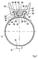
- FIG. 1 there is a substantially tubular cell 10 of a missile Clamp 12 placed around and by a tightening device 14 around the missile tightened.
- the clamp 12 has a block-like thickening 16.
- the thickening 16 forms on its outside a longitudinal channel 18 of trapezoidal cross-section with a tangential base 20 and at an angle of 45 ° to the base 20 extending inclined surfaces 22 and 24. Close to the inclined surfaces 22 and 24 1 again tangential edge surfaces 26 and 28.
- Longitudinal channel 18 is a hook or "hanger” 30 out.
- the hook 30 has one Middle part 32 with one to the longitudinal channel 18 and the edge surfaces 26 and 28 complementary inner surface with which the hook 30 is guided on the thickening.
- the hook 30 is screwed to the thickening 16 by screws 48 and 50.
- the axes of the Screws 48 and 50 extend at an angle of 45 ° from the outer surface 34 to the outside, perpendicular to the inclined surfaces 22 and 24 of the longitudinal channel 18 and complementary inner surface of the hook 30.
- the heads of the screws 48 and 50 are housed in the recesses 36 and 38.
- the hook 30 forms two opposite support rails 52 and 54 on both sides of the central part 32.
- Die Support rails 52 and 54 are made in one piece with the central part and protrude laterally beyond the thickening 16 and the central part 32.
- the support rails 52 and 54 rest on guide strips 56 and 58 of the starting device.
- the structure of the Starting device is known per se and is therefore not described in more detail here.
- Fig.2 The execution of Fig.2 is constructed similarly to the execution of Fig.1, and corresponding parts are provided with the same reference numerals as there.
- the clamp 12 is omitted. Instead, the thickening is 60 molded onto the tubular cell 10 of the missile.
- middle part 32 and the thickening 16 are longer than the support rails 52 and 54.
- middle part 32 and thickening 16 are axial by a plurality mutually offset screw connections that run at an angle of 45 ° to the outside 62 connected to each other in the manner described.
- the hook arrangements described are compatible with existing systems. In the event of a shift in the center of gravity caused by the refitting of the missile the clamps can be moved lengthways with the hooks.
Landscapes
- Engineering & Computer Science (AREA)
- Aviation & Aerospace Engineering (AREA)
- General Engineering & Computer Science (AREA)
- Clamps And Clips (AREA)
- Load-Engaging Elements For Cranes (AREA)
Abstract
Description
- Fig.1
- zeigt eine Haken-Anordnung, bei welcher der Haken an einer Schelle oder "Bauchbinde" angebracht ist.
- Fig.2
- zeigt eine Anordnung, bei welcher der Haken an einer Verdickung der rohrförmigen Zelle des Flugkörpers angebracht ist.
- Fig.3
- ist eine schematisch-perspektivische Darstellung der Haken-Anordnung.
Claims (6)
- Haken-Anordnung bei Flugkörpern, bei welcher ein Haken (30) mit gegenüberliegenden Tragschienen (52,54) zur Führung des Flugkörpers in einem Startgerät mit dem Flugkörper über eine Schraubverbindung verbunden ist, dadurch gekennzeichnet, daß flugkörperseitig eine Verdickung (16;60) vorgesehen ist, und der Haken (30) durch Schrauben (48,50) von der Außenseite her mit der Verdickung (16;60) verschraubt ist.
- Haken-Anordnung nach Anspruch 1, dadurch gekennzeichnet, daß an dem Flugkörper eine die Zelle (10) des Flugkörpers umgebende, mit der Verdickung (16) versehene Schelle (12) angebracht ist.
- Haken-Anordnung nach Anspruch 1 oder 2, dadurch gekennzeichnet, daß die Verschraubung des Hakens (30) durch Verschraubungen (44,48;46,50) erfolgt, deren Achsen mit der Ebene der Tragschienen (52,54) einen Winkel bildet.
- Haken-Anordnung nach Anspruch 3, dadurch gekennzeichnet, daß die Achsen der Verschraubungen (44,48;46,50) unter 45° zur Ebene der Tragschienen (52,54) nach außen verlaufen.
- Haken-Anordnung nach Anpruch 3 oder 4, dadurch gekennzeichnet, daß(a) die Verdickung (16) einen Längskanal (18) von trapezförmigem Querschnitt aufweist,(b) der Haken (30) einen an den Längskanal (18) angepaßten Mittelteil (32) aufweist,(c) der Mittelteil (32) mit der Verdickung (16) durch schräg verlaufende Verschraubungen (44,48;46,50) verbunden ist, welche durch die Schrägseiten des Mittelteils (32) des Hakens (30) und des Längskanals (18) geführt sind, und(d) die Tragschienen (52,54) sich zu beiden Seiten des Mittelteils (32) über die Verdickung (16) hinaus nach außen erstrecken.
- Haken-Anordnung nach Anspruch 5, dadurch gekennzeichnet, daß der Mittelteil (32) und die Verdickung (16) länger sind als die Tragschienen (52,54) und durch eine Mehrzahl von axial gegeneinander versetzten Schrägverschraubungen (62;Fig.3) miteinander verbunden sind.
Applications Claiming Priority (2)
| Application Number | Priority Date | Filing Date | Title |
|---|---|---|---|
| DE19715972A DE19715972A1 (de) | 1997-04-17 | 1997-04-17 | Haken-Anordnung bei Flugkörpern |
| DE19715972 | 1997-04-17 |
Publications (3)
| Publication Number | Publication Date |
|---|---|
| EP0872416A2 true EP0872416A2 (de) | 1998-10-21 |
| EP0872416A3 EP0872416A3 (de) | 1999-11-17 |
| EP0872416B1 EP0872416B1 (de) | 2003-10-29 |
Family
ID=7826734
Family Applications (1)
| Application Number | Title | Priority Date | Filing Date |
|---|---|---|---|
| EP98106790A Expired - Lifetime EP0872416B1 (de) | 1997-04-17 | 1998-04-15 | Haken-Anordnung bei Flugkörpern |
Country Status (4)
| Country | Link |
|---|---|
| US (1) | US5970842A (de) |
| EP (1) | EP0872416B1 (de) |
| DE (2) | DE19715972A1 (de) |
| ES (1) | ES2210613T3 (de) |
Families Citing this family (12)
| Publication number | Priority date | Publication date | Assignee | Title |
|---|---|---|---|---|
| GB0100277D0 (en) | 2001-01-05 | 2001-02-14 | Flight Refueling Ltd | Release suspension for an airborne store |
| US6663048B2 (en) * | 2002-01-16 | 2003-12-16 | Lockheed Martin Corporation | Mounting structure for attaching a payload, such as a warhead, to munitions |
| KR20020059278A (ko) * | 2002-06-07 | 2002-07-12 | (주) 스페이스 리서치 | 자동 탈락형 로켓 런치 러그 |
| DE10254974A1 (de) * | 2002-11-26 | 2004-06-17 | Bayern-Chemie Gesellschaft Für Flugchemische Antriebe Mbh | Vorrichtung zum Ankoppeln eines Flugkörpers an ein Flugzeug |
| WO2004108529A2 (en) * | 2003-03-06 | 2004-12-16 | Drs Training & Control Systems, Inc. | Hanger assembly for aircraft |
| IL165812A (en) * | 2004-12-16 | 2011-09-27 | Rafael Advanced Defense Sys | Detachable hanger for rail-launched flying objects such as missiles and airborne platforms |
| US7624947B2 (en) * | 2007-06-07 | 2009-12-01 | Black Rum Engineering Services LLC | Armament carriage system |
| DE602008002997D1 (de) * | 2008-03-06 | 2010-11-25 | Saab Ab | Raketenentlasssystem und Hängeglied zur Aufhängung der Rakete in einer Entlassschiene |
| US8333138B2 (en) * | 2008-09-12 | 2012-12-18 | Raytheon Company | Composite reinforced missile rail |
| US8256338B1 (en) * | 2010-01-06 | 2012-09-04 | The United States Of America As Represented By The Secretary Of The Navy | Weapon and weapon station system and method for loading, testing, targeting, and launching a weapon |
| CN113124714A (zh) * | 2019-12-31 | 2021-07-16 | 南京儒一航空机械装备有限公司 | 一种弹翼横梁前吊挂组合及其加工工艺 |
| CN113247749A (zh) * | 2021-05-11 | 2021-08-13 | 中国航空制造技术研究院 | 一种筒体吊挂结构及其制造方法 |
Family Cites Families (5)
| Publication number | Priority date | Publication date | Assignee | Title |
|---|---|---|---|---|
| FR865703A (fr) * | 1940-02-05 | 1941-05-31 | Dispositif récupérateur de ceintures de bombes et pièces d'accrochage | |
| US3132590A (en) * | 1954-10-18 | 1964-05-12 | Bell Aerospace Corp | Missile with separable components |
| DE3016925A1 (de) * | 1980-05-02 | 1981-11-12 | Dornier Gmbh, 7990 Friedrichshafen | Starteinrichtung zum tragen und starten von flugkoerpern, insbesondere fuer luftfahrzeuge |
| GB8627530D0 (en) * | 1986-11-18 | 1987-07-08 | British Aerospace | Missiles and launcher apparatus |
| US5094140A (en) * | 1991-03-11 | 1992-03-10 | Techteam, Inc. | Missile launcher assembly |
-
1997
- 1997-04-17 DE DE19715972A patent/DE19715972A1/de not_active Withdrawn
-
1998
- 1998-04-10 US US09/058,216 patent/US5970842A/en not_active Expired - Lifetime
- 1998-04-15 EP EP98106790A patent/EP0872416B1/de not_active Expired - Lifetime
- 1998-04-15 DE DE59809995T patent/DE59809995D1/de not_active Expired - Lifetime
- 1998-04-15 ES ES98106790T patent/ES2210613T3/es not_active Expired - Lifetime
Non-Patent Citations (1)
| Title |
|---|
| None |
Also Published As
| Publication number | Publication date |
|---|---|
| ES2210613T3 (es) | 2004-07-01 |
| EP0872416B1 (de) | 2003-10-29 |
| EP0872416A3 (de) | 1999-11-17 |
| DE19715972A1 (de) | 1998-10-22 |
| DE59809995D1 (de) | 2003-12-04 |
| US5970842A (en) | 1999-10-26 |
Similar Documents
| Publication | Publication Date | Title |
|---|---|---|
| DE3814799A1 (de) | Dachtraegersystem fuer ein fahrzeug | |
| DE2647235C2 (de) | Distanzhalter für durch Schutzrohre hindurchgeführte Rohre | |
| DE69409667T2 (de) | Scharniereinrichtung | |
| EP0872416A2 (de) | Haken-Anordnung bei Flugkörpern | |
| EP0499791B1 (de) | Energieführungskette | |
| DE2544272C3 (de) | Triebwerksaufhängung an Luftfahrzeugen | |
| EP0572607B1 (de) | Vorrichtung zum eindrehen und setzen von selbstbohrenden zugblindnieten | |
| DE102018123251B4 (de) | Schienensystem zum Befestigen von Einbauten in einer Kabine eines Fahrzeugs | |
| DE3831807A1 (de) | Niederhaltevorrichtung | |
| DE3122616C2 (de) | Vorrichtung zur Mitnahme von Lasten unter einem Flugzeug | |
| DE69200589T2 (de) | Verbesserte abschussschiene fuer flugkoerper. | |
| DE3209205A1 (de) | Fuehrungshalter fuer elektronische baugruppen | |
| DE3819351A1 (de) | Startvorrichtung fuer luftgestuetzte flugkoerper | |
| DE19523931C1 (de) | Vorbaustruktur für ein Kraftfahrzeug | |
| EP0577976A1 (de) | Klemmvorrichtung | |
| DE2857442A1 (de) | Segelaufnahme- und -abgabemagazin fuer einen segeltraeger | |
| EP0138233A2 (de) | Kotflügel | |
| DE19724105C1 (de) | Befestigungseinrichtung für einen Behältnisträger an einer Transportvorrichtung | |
| DE3843765A1 (de) | Befestigungselement | |
| DE3725036A1 (de) | Verbindungseinrichtung fuer rumpfteile | |
| DE8903814U1 (de) | Befestigungselement | |
| DE4002446A1 (de) | Vorrichtung zum loesbaren festsetzen von schutzplatten und dergleichen | |
| DE102021108000A1 (de) | Befestigungssystem und Befestigungsverfahren zum Befestigen einer Komponente in einer Kabine | |
| DE2802288C3 (de) | Spannvorrichtung für Kettenstränge | |
| DE2750962C2 (de) | Abwurfvorrichtung für eine unter einem Flugzeug mitgeführte Last |
Legal Events
| Date | Code | Title | Description |
|---|---|---|---|
| PUAI | Public reference made under article 153(3) epc to a published international application that has entered the european phase |
Free format text: ORIGINAL CODE: 0009012 |
|
| AK | Designated contracting states |
Kind code of ref document: A2 Designated state(s): DE ES GB GR IT SE |
|
| AX | Request for extension of the european patent |
Free format text: AL;LT;LV;MK;RO;SI |
|
| PUAL | Search report despatched |
Free format text: ORIGINAL CODE: 0009013 |
|
| AK | Designated contracting states |
Kind code of ref document: A3 Designated state(s): AT BE CH CY DE DK ES FI FR GB GR IE IT LI LU MC NL PT SE |
|
| AX | Request for extension of the european patent |
Free format text: AL;LT;LV;MK;RO;SI |
|
| RIC1 | Information provided on ipc code assigned before grant |
Free format text: 6B 64D 1/04 A, 6B 64D 7/08 B, 6F 41F 3/04 B |
|
| 17P | Request for examination filed |
Effective date: 19991028 |
|
| AKX | Designation fees paid |
Free format text: DE ES GB GR IT SE |
|
| 17Q | First examination report despatched |
Effective date: 20020705 |
|
| GRAH | Despatch of communication of intention to grant a patent |
Free format text: ORIGINAL CODE: EPIDOS IGRA |
|
| GRAS | Grant fee paid |
Free format text: ORIGINAL CODE: EPIDOSNIGR3 |
|
| GRAA | (expected) grant |
Free format text: ORIGINAL CODE: 0009210 |
|
| AK | Designated contracting states |
Kind code of ref document: B1 Designated state(s): DE ES GB GR IT SE |
|
| REG | Reference to a national code |
Ref country code: GB Ref legal event code: FG4D Free format text: NOT ENGLISH |
|
| REF | Corresponds to: |
Ref document number: 59809995 Country of ref document: DE Date of ref document: 20031204 Kind code of ref document: P |
|
| REG | Reference to a national code |
Ref country code: SE Ref legal event code: TRGR |
|
| GBT | Gb: translation of ep patent filed (gb section 77(6)(a)/1977) |
Effective date: 20040121 |
|
| REG | Reference to a national code |
Ref country code: GR Ref legal event code: EP Ref document number: 20040400136 Country of ref document: GR |
|
| REG | Reference to a national code |
Ref country code: ES Ref legal event code: FG2A Ref document number: 2210613 Country of ref document: ES Kind code of ref document: T3 |
|
| PLBE | No opposition filed within time limit |
Free format text: ORIGINAL CODE: 0009261 |
|
| STAA | Information on the status of an ep patent application or granted ep patent |
Free format text: STATUS: NO OPPOSITION FILED WITHIN TIME LIMIT |
|
| 26N | No opposition filed |
Effective date: 20040730 |
|
| REG | Reference to a national code |
Ref country code: DE Ref legal event code: R081 Ref document number: 59809995 Country of ref document: DE Owner name: DIEHL DEFENCE GMBH & CO. KG, DE Free format text: FORMER OWNER: DIEHL BGT DEFENCE GMBH & CO. KG, 88662 UEBERLINGEN, DE |
|
| PGFP | Annual fee paid to national office [announced via postgrant information from national office to epo] |
Ref country code: GB Payment date: 20170419 Year of fee payment: 20 Ref country code: DE Payment date: 20170614 Year of fee payment: 20 Ref country code: GR Payment date: 20170425 Year of fee payment: 20 |
|
| PGFP | Annual fee paid to national office [announced via postgrant information from national office to epo] |
Ref country code: ES Payment date: 20170517 Year of fee payment: 20 Ref country code: SE Payment date: 20170419 Year of fee payment: 20 Ref country code: IT Payment date: 20170424 Year of fee payment: 20 |
|
| REG | Reference to a national code |
Ref country code: DE Ref legal event code: R071 Ref document number: 59809995 Country of ref document: DE |
|
| REG | Reference to a national code |
Ref country code: GB Ref legal event code: PE20 Expiry date: 20180414 |
|
| REG | Reference to a national code |
Ref country code: SE Ref legal event code: EUG |
|
| PG25 | Lapsed in a contracting state [announced via postgrant information from national office to epo] |
Ref country code: GB Free format text: LAPSE BECAUSE OF EXPIRATION OF PROTECTION Effective date: 20180414 |
|
| REG | Reference to a national code |
Ref country code: ES Ref legal event code: FD2A Effective date: 20200721 |
|
| PG25 | Lapsed in a contracting state [announced via postgrant information from national office to epo] |
Ref country code: ES Free format text: LAPSE BECAUSE OF EXPIRATION OF PROTECTION Effective date: 20180416 |