EP0872446A2 - Installation hydraulique pour chariot élévateur à fourche - Google Patents
Installation hydraulique pour chariot élévateur à fourche Download PDFInfo
- Publication number
- EP0872446A2 EP0872446A2 EP98107020A EP98107020A EP0872446A2 EP 0872446 A2 EP0872446 A2 EP 0872446A2 EP 98107020 A EP98107020 A EP 98107020A EP 98107020 A EP98107020 A EP 98107020A EP 0872446 A2 EP0872446 A2 EP 0872446A2
- Authority
- EP
- European Patent Office
- Prior art keywords
- valve
- pressure
- piston
- drive
- stroke
- Prior art date
- Legal status (The legal status is an assumption and is not a legal conclusion. Google has not performed a legal analysis and makes no representation as to the accuracy of the status listed.)
- Granted
Links
Images



Classifications
-
- B—PERFORMING OPERATIONS; TRANSPORTING
- B66—HOISTING; LIFTING; HAULING
- B66F—HOISTING, LIFTING, HAULING OR PUSHING, NOT OTHERWISE PROVIDED FOR, e.g. DEVICES WHICH APPLY A LIFTING OR PUSHING FORCE DIRECTLY TO THE SURFACE OF A LOAD
- B66F9/00—Devices for lifting or lowering bulky or heavy goods for loading or unloading purposes
- B66F9/06—Devices for lifting or lowering bulky or heavy goods for loading or unloading purposes movable, with their loads, on wheels or the like, e.g. fork-lift trucks
- B66F9/075—Constructional features or details
- B66F9/20—Means for actuating or controlling masts, platforms, or forks
- B66F9/22—Hydraulic devices or systems
-
- F—MECHANICAL ENGINEERING; LIGHTING; HEATING; WEAPONS; BLASTING
- F15—FLUID-PRESSURE ACTUATORS; HYDRAULICS OR PNEUMATICS IN GENERAL
- F15B—SYSTEMS ACTING BY MEANS OF FLUIDS IN GENERAL; FLUID-PRESSURE ACTUATORS, e.g. SERVOMOTORS; DETAILS OF FLUID-PRESSURE SYSTEMS, NOT OTHERWISE PROVIDED FOR
- F15B11/00—Servomotor systems without provision for follow-up action; Circuits therefor
- F15B11/02—Systems essentially incorporating special features for controlling the speed or actuating force of an output member
- F15B11/04—Systems essentially incorporating special features for controlling the speed or actuating force of an output member for controlling the speed
- F15B11/05—Systems essentially incorporating special features for controlling the speed or actuating force of an output member for controlling the speed specially adapted to maintain constant speed, e.g. pressure-compensated, load-responsive
-
- F—MECHANICAL ENGINEERING; LIGHTING; HEATING; WEAPONS; BLASTING
- F15—FLUID-PRESSURE ACTUATORS; HYDRAULICS OR PNEUMATICS IN GENERAL
- F15B—SYSTEMS ACTING BY MEANS OF FLUIDS IN GENERAL; FLUID-PRESSURE ACTUATORS, e.g. SERVOMOTORS; DETAILS OF FLUID-PRESSURE SYSTEMS, NOT OTHERWISE PROVIDED FOR
- F15B13/00—Details of servomotor systems ; Valves for servomotor systems
- F15B13/01—Locking-valves or other detent i.e. load-holding devices
- F15B13/015—Locking-valves or other detent i.e. load-holding devices using an enclosed pilot flow valve
-
- F—MECHANICAL ENGINEERING; LIGHTING; HEATING; WEAPONS; BLASTING
- F15—FLUID-PRESSURE ACTUATORS; HYDRAULICS OR PNEUMATICS IN GENERAL
- F15B—SYSTEMS ACTING BY MEANS OF FLUIDS IN GENERAL; FLUID-PRESSURE ACTUATORS, e.g. SERVOMOTORS; DETAILS OF FLUID-PRESSURE SYSTEMS, NOT OTHERWISE PROVIDED FOR
- F15B13/00—Details of servomotor systems ; Valves for servomotor systems
- F15B13/02—Fluid distribution or supply devices characterised by their adaptation to the control of servomotors
- F15B13/04—Fluid distribution or supply devices characterised by their adaptation to the control of servomotors for use with a single servomotor
- F15B13/044—Fluid distribution or supply devices characterised by their adaptation to the control of servomotors for use with a single servomotor operated by electrically-controlled means, e.g. solenoids, torque-motors
-
- F—MECHANICAL ENGINEERING; LIGHTING; HEATING; WEAPONS; BLASTING
- F15—FLUID-PRESSURE ACTUATORS; HYDRAULICS OR PNEUMATICS IN GENERAL
- F15B—SYSTEMS ACTING BY MEANS OF FLUIDS IN GENERAL; FLUID-PRESSURE ACTUATORS, e.g. SERVOMOTORS; DETAILS OF FLUID-PRESSURE SYSTEMS, NOT OTHERWISE PROVIDED FOR
- F15B2211/00—Circuits for servomotor systems
- F15B2211/30—Directional control
- F15B2211/305—Directional control characterised by the type of valves
- F15B2211/30525—Directional control valves, e.g. 4/3-directional control valve
-
- F—MECHANICAL ENGINEERING; LIGHTING; HEATING; WEAPONS; BLASTING
- F15—FLUID-PRESSURE ACTUATORS; HYDRAULICS OR PNEUMATICS IN GENERAL
- F15B—SYSTEMS ACTING BY MEANS OF FLUIDS IN GENERAL; FLUID-PRESSURE ACTUATORS, e.g. SERVOMOTORS; DETAILS OF FLUID-PRESSURE SYSTEMS, NOT OTHERWISE PROVIDED FOR
- F15B2211/00—Circuits for servomotor systems
- F15B2211/30—Directional control
- F15B2211/32—Directional control characterised by the type of actuation
- F15B2211/327—Directional control characterised by the type of actuation electrically or electronically
-
- F—MECHANICAL ENGINEERING; LIGHTING; HEATING; WEAPONS; BLASTING
- F15—FLUID-PRESSURE ACTUATORS; HYDRAULICS OR PNEUMATICS IN GENERAL
- F15B—SYSTEMS ACTING BY MEANS OF FLUIDS IN GENERAL; FLUID-PRESSURE ACTUATORS, e.g. SERVOMOTORS; DETAILS OF FLUID-PRESSURE SYSTEMS, NOT OTHERWISE PROVIDED FOR
- F15B2211/00—Circuits for servomotor systems
- F15B2211/30—Directional control
- F15B2211/35—Directional control combined with flow control
- F15B2211/351—Flow control by regulating means in feed line, i.e. meter-in control
-
- F—MECHANICAL ENGINEERING; LIGHTING; HEATING; WEAPONS; BLASTING
- F15—FLUID-PRESSURE ACTUATORS; HYDRAULICS OR PNEUMATICS IN GENERAL
- F15B—SYSTEMS ACTING BY MEANS OF FLUIDS IN GENERAL; FLUID-PRESSURE ACTUATORS, e.g. SERVOMOTORS; DETAILS OF FLUID-PRESSURE SYSTEMS, NOT OTHERWISE PROVIDED FOR
- F15B2211/00—Circuits for servomotor systems
- F15B2211/30—Directional control
- F15B2211/35—Directional control combined with flow control
- F15B2211/353—Flow control by regulating means in return line, i.e. meter-out control
-
- F—MECHANICAL ENGINEERING; LIGHTING; HEATING; WEAPONS; BLASTING
- F15—FLUID-PRESSURE ACTUATORS; HYDRAULICS OR PNEUMATICS IN GENERAL
- F15B—SYSTEMS ACTING BY MEANS OF FLUIDS IN GENERAL; FLUID-PRESSURE ACTUATORS, e.g. SERVOMOTORS; DETAILS OF FLUID-PRESSURE SYSTEMS, NOT OTHERWISE PROVIDED FOR
- F15B2211/00—Circuits for servomotor systems
- F15B2211/60—Circuit components or control therefor
- F15B2211/63—Electronic controllers
- F15B2211/6303—Electronic controllers using input signals
- F15B2211/6306—Electronic controllers using input signals representing a pressure
- F15B2211/6313—Electronic controllers using input signals representing a pressure the pressure being a load pressure
-
- F—MECHANICAL ENGINEERING; LIGHTING; HEATING; WEAPONS; BLASTING
- F15—FLUID-PRESSURE ACTUATORS; HYDRAULICS OR PNEUMATICS IN GENERAL
- F15B—SYSTEMS ACTING BY MEANS OF FLUIDS IN GENERAL; FLUID-PRESSURE ACTUATORS, e.g. SERVOMOTORS; DETAILS OF FLUID-PRESSURE SYSTEMS, NOT OTHERWISE PROVIDED FOR
- F15B2211/00—Circuits for servomotor systems
- F15B2211/60—Circuit components or control therefor
- F15B2211/665—Methods of control using electronic components
-
- F—MECHANICAL ENGINEERING; LIGHTING; HEATING; WEAPONS; BLASTING
- F15—FLUID-PRESSURE ACTUATORS; HYDRAULICS OR PNEUMATICS IN GENERAL
- F15B—SYSTEMS ACTING BY MEANS OF FLUIDS IN GENERAL; FLUID-PRESSURE ACTUATORS, e.g. SERVOMOTORS; DETAILS OF FLUID-PRESSURE SYSTEMS, NOT OTHERWISE PROVIDED FOR
- F15B2211/00—Circuits for servomotor systems
- F15B2211/60—Circuit components or control therefor
- F15B2211/665—Methods of control using electronic components
- F15B2211/6654—Flow rate control
-
- F—MECHANICAL ENGINEERING; LIGHTING; HEATING; WEAPONS; BLASTING
- F15—FLUID-PRESSURE ACTUATORS; HYDRAULICS OR PNEUMATICS IN GENERAL
- F15B—SYSTEMS ACTING BY MEANS OF FLUIDS IN GENERAL; FLUID-PRESSURE ACTUATORS, e.g. SERVOMOTORS; DETAILS OF FLUID-PRESSURE SYSTEMS, NOT OTHERWISE PROVIDED FOR
- F15B2211/00—Circuits for servomotor systems
- F15B2211/70—Output members, e.g. hydraulic motors or cylinders or control therefor
- F15B2211/76—Control of force or torque of the output member
- F15B2211/761—Control of a negative load, i.e. of a load generating hydraulic energy
Definitions
- the invention relates to a hydraulic installation on one Forklift truck with a hydraulic lift drive for a lift, with another hydraulic drive as a tilt actuator as well as with these hydraulic drives individually assigned valve arrangements, by means of those for the different movements of the lift required operating pressures and pressure medium flow rates are controllable, and with the further in the preamble of claim 1, generic Characteristics.
- the linear actuator by means of whose masses can be raised and lowered must be, which can be up to a few t designed as a single-acting hydraulic cylinder, its lifting operation through valve-controlled pressure medium inflow to Drive pressure chamber and its lowering operation through valve-controlled Influence of pressure medium from the drive pressure chamber the hydraulic cylinder is controllable.
- the necessary for this Control valve assembly includes a stroke control valve about the pressure medium from the pressure supply unit can be fed into the drive pressure chamber of the stroke drive cylinder is, as well as a lowering control valve, by means of whose the inflow of pressure medium from the drive pressure chamber of the linear actuator and thus its lowering operation is controllable.
- the two valves are, their basic function after designed as 2/2-way proportional valves, the one have a blocking basic position and with increasing deflection their valve piston from the basic position flow paths release with increasing flow cross-section, whereby between the consumer port of the boost control valve and the drive pressure chamber of the lifting cylinder a check valve is switched by relatively higher Pressure at the consumer connection than in the drive pressure chamber is continuous and otherwise blocking, and between the consumer connection of the lowering control valve and the drive pressure chamber of the linear actuator an unlockable check valve is switched, which is in the blocking basic position of the lowering control valve is blocking and with whose transition to the flow position is switched.
- control valves In an electrically controllable design of these control valves are their valve bodies with the armatures of electromagnet systems coupled with movement and when energized essentially proportional to the excitation current against the Restoring force of valve springs that move the valve body in the de-energized state of the magnets in the basic position of the valves hold.
- the energization of the field windings takes place through output currents of an electronic Control unit that this according to setpoint input signals generated, e.g. by hand lever or rotary knob confirmation of an analog signal generator by a forklift driver can be triggered, the electronic Control unit, however, also in digital format, e.g. at Using a radio remote control can be entered and by means of this into the - analog - excitation currents can be implemented for the field windings of the control magnets.
- the object of the invention is therefore a hydraulic installation of the type mentioned at the outset to improve that even with a small amount of a load to be lowered a comparatively high lowering speed can be used is, and that at the same time simple construction of the stroke control valve assembly an increased level of accuracy of adjustment the effective in the raising and lowering operation Flow cross sections is guaranteed.
- the stroke control valve arrangement is a multi-way / 3-position valve trained that has a main piston which by means of an electric servomotor in his various functional positions of the stroke control valve arrangement corresponding positions is movable by positive movement coupling of the valve piston with the Output shaft of the servomotor in a defined relation to the azimuthal positions related to a reference position stand of the rotor of the servomotor, the servomotor is designed as a digitally controllable motor, the Rotor into a digital control signal, e.g. the number a sequence of control pulses, coded azimuthal position its output shaft - forcibly - reached.
- a pressure sensor is also provided, that for the pressure in the drive pressure chamber of the stroke drive cylinder characteristic electrical output signals generated, which is fed to an electronic control unit are, according to this pressure and thus also load-characteristic output signals of the pressure sensor an automatic limitation of the modulation stroke of the Main piston of the stroke control valve mediated to an amount which is a load-permissible maximum value of the lifting and The lowering speed of the lift corresponds to below each of which is a dynamically stable, essentially vibration-free operation of the lift is guaranteed is.
- a design of the electronic control unit which is expedient for the lowering operation can consist in that with a decreasing load an increase in the actuation range of the valve piston is permitted, in that the same value of the maximum lowering speed can be used for all loads.
- Due to the mass dependency of the characteristic frequency ⁇ 0 of a hydraulic powertrain, generally by the relationship ⁇ 0 C. m is given, in which the hydraulic stiffness of the drive train is denoted by C and the moving mass is denoted by m, larger speeds and accelerations or decelerations can also be used with decreasing amount of the moving mass.
- Such a transmission is in a preferred design as Spindle nut drive formed, in which preferably the Spindle as a threaded section of the output shaft of the servomotor is trained and the spindle nut firmly with the Piston connected and preferably in one piece with the piston is executed, which in turn is secured against rotation in the valve housing is guided.
- the design of the stroke control valve arrangement provided according to claim 4 with two by deflections of the main piston openable seat valves, by means of which the lowering movements the lift is controllable has the advantage that all valve elements of the stroke control valve assembly in a single multi-way three-position valve with a single actuator and a simple one and space-saving construction is achieved.
- the pulse width modulated solenoid valves provided for the operation control of further hydraulic drives of the hydraulic installations, for which values of frequencies f m for the amplitude modulation and for the pulse repetition frequency f i of "carrier" pulses indicated by the features of claim 9 are from which the amplitude or duration-modulated pulses of the duration T 1 and T 2 are synthesized, have the advantage that from a minimum current of the time-modulated pulses the deflection of the valve body from the respective basic position regardless of the current of the Impulse is, ie only depends on the ratio T 1 / T 2 , which in turn can be controlled digitally, with the result that the reproducibility of defined deflections is considerably better in comparison to conventional proportional solenoid valves.
- Control block a multi-layer structure made of segment sheets provided that are cohesively connected, in practice are brazed together and with recesses are provided by their contours and Arrangement to each other the cross-sectional shapes and the clear Dimensions of transverse and longitudinal channels as well as valve channels and control chambers within the control block are, which are required to form the cavities mentioned Openings e.g. in a laser cutting process or created using fineblanking or stamping technology are.
- the manufacture of the control block is therefore essential easier than manufacturing using conventional casting technology.
- the solder material required for the solder connection can be inserted in segment recesses in one prepared for stacking segment sheet metal in closed cavities form from which the solder passes through the capillary action of the narrow gaps between the segment sheets into the configuration connecting this large area can reach.
- Pressure (P) supply channels and return channels, to the supply connections of the individual Valves can be easily bypassed of cross channels in which e.g. Sliding valve piston are arranged completely within the housing block be formed.
- For connection to hydraulic consumers or to the connection piece provided on the pressure supply unit can be designed as prefabricated parts, which are soldered into the mouth of the control block. Compared to those made with conventional casting technology Housings are significant for the control block smaller outer dimensions and also a considerable weight reduction.
- Fig. 1 is a total of 10, the hydraulic installation a forklift vehicle, not otherwise shown referred to, by means of which loads up to several tons, e.g. with heavy metal parts loaded transport pallets, for storing such Parts of the designated storage spaces of a high-bay warehouse parked or removed from such storage locations can be, the approach to such bearings and the storage of the goods on them or their removal is controlled by such a driver who is the forklift "drives" and "controls".
- Such a forklift truck if it is for one Use in closed storage rooms is intended to be battery powered, electric travel drive and - also emission-free - hydraulic drives for additional equipment, by means of which the load in the storage position brought and stored there or in the storage position approached and picked up again can.
- the hydraulic installation 10 includes the forklift a stroke drive cylinder 11, by means of which one - fork-shaped - lift, which take up the payload can, on a not shown, substantially vertically Move the mast of the forklift up and down can be made to go to predetermined heights of storage floors Raised or picked up from these can.
- This stroke drive cylinder 11 is a single-acting linear hydraulic cylinder designed by valve-controlled Pressurization of a drive pressure chamber 12 in In order to raise the lift or the load works and with valve-controlled pressure relief this too Drive pressure chamber 12 by the weight of the piston 13 of the stroke drive cylinder 11 supported load Lowering mediated.
- the lifting and lowering movements of this lifting drive cylinder 11 are controllable by means of a stroke control valve 14, which is designed as a three-position directional valve, the one function position I assigned to the lifting operation, one to the Lowering operation of the stroke drive cylinder 11 assigned Function position II and one of the shutdown of the stroke drive cylinder 11 assigned basic position has 0, the the driver by means of a manually operated direction selector 106, e.g. a swivel lever, can specify wherein the stroke control valve is designed so that when the driver does not operate the direction selector 106 - "lets go" - automatically into the return springs 17 and 18 centered home position 0, in which the stroke drive cylinder 11 has stopped.
- a stroke control valve 14 which is designed as a three-position directional valve, the one function position I assigned to the lifting operation, one to the Lowering operation of the stroke drive cylinder 11 assigned Function position II and one of the shutdown of the stroke drive cylinder 11 assigned basic position has 0, the the driver by means of a manually operated direction selector 106,
- the hydraulic installation 10 includes one Inclination adjusting cylinder 19, by means of which in the front area of the vehicle immediately in front of its front axle Lift mast within a limited angular range around a parallel to the front axle of the truck running axle close to the road to the vehicle can be tilted towards or away from the vehicle to thereby also one to the lane or to the storage area of the stored goods downward or upward orientation of the fork of the forklift, i.e. the for that Loading and unloading and good orientations for driving of the mast and the fork.
- the tilt actuator cylinder 19 is a double-acting linear Hydraulic cylinder designed, the bottom-side drive pressure chamber 21 and its rod-side drive pressure chamber 22 by means of these individually assigned preload valves 23 and 24, which act as pressure relief valves are designed with adjustable pressure limit values, are kept under a minimum pressure.
- Thrust actuator 26 is provided for moving the load is usable from the fork to the bearing on which the stored goods are to be parked.
- This thrust drive is also in Fig. 1 by a double-acting represents linear hydraulic cylinder 26.
- the lift of the forklift with a low-build, only schematically indicated rotary table 27 is equipped, the by means of a hydraulic one designated 28 overall Rotary drive by at least 180 ° clockwise and counterclockwise is rotatable so that one on the turntable 27 pallets parked in any case in one for parking desired, any orientation is rotatable before them by means of the linear actuator 26 on the respectively provided Storage space is moved.
- this rotary drive is realized by means of two single-acting linear hydraulic cylinders 28 1 and 28 2 , which can be actuated in one or the other direction of rotation by alternative pressurization and relief of their drive pressure chambers 29 1 and 29 2 arranged on the rod side for driving the rotary table 27 .
- a toothed belt 32 which meshes with a gear 31 of the turntable 27 can be provided, which adjoins the piston rods 30 1 and 30 2 which run parallel to one another Hydraulic cylinder 28 1 and 282 connects to each other and is held on a 180 ° circumferential area of the gear 31 with this in a positive-locking engagement.
- the Thrust cylinder 26 and the rotary drive 28 are each individually assigned proportional valves 33, 34 and 36 of the same Provided type, which is based on the Thrust cylinder 26 associated thrust control valve 34 explained becomes:
- the thrust cylinder control valve 34 is a linear slide valve trained, the piston, corresponding to the functions mediated by the control valve 34 through a 5/3-way valve symbol 34 'is represented. Corresponding are the valve pistons of the other two control valves 33 and 36 with 33 'and 36' respectively.
- a double-stroke magnet system is used to actuate the control valve 34 37 provided, the two by a control connection 38 or 39 represented field windings, in the non-energized state of the piston 34 'of the control valve 34 by the action of preloaded valve springs 41 and 42 occupies its centered center position, which the Home position 0 of the control valve 34 corresponds to the the shutdown of the push cylinder 26 is linked.
- a sufficiently high modulation frequency f m of, for example, 500 Hz, with which the control windings 38 and 39 of the double-stroke magnet system 37 are driven alternately with current pulses of the same current intensity but different pulse durations T 1 and T 2 within the period T of the current pulses, is used by the Mechanical inertia of the armature of the double-stroke magnet system 37 and of the valve piston 34 'coupled with this movement ensures that the reciprocating movements of the armature and the valve piston which occur in time with the modulation frequency f m only have amplitudes which are small compared to the deflections of the valve piston 34' from it Home position 0, so that the effective deflection from the home position 0 is determined by the ratio of the time periods T 1 and T 2 .
- the control valve 34 is hydraulic in terms of achievable Pipe connections a 5/3-way valve that a pressure (P) supply connection 48 on the supply side has, via a pressure supply line 49 to the pressure outlet 51 of the pressure supply unit, denoted overall by 52 connected, a return (T) connection 53, which is connected via a return line 54 the reservoir 56 of the pressure supply unit 52 connected and a load (x) sensing connector 57 associated with one of the connected consumers 26
- Inlet port 58 of a shuttle valve 59 connected is, depending on whether the load sensing connection 57 prevailing pressure is lower or higher than the pending at the other inlet connection 61 of the shuttle valve 59 Press the load sensing port 57 of the control valve 34 blocks against the output 62 of the shuttle valve or connects to the output 62 of the shuttle valve 59.
- control valve 34 On the consumer side, the control valve 34 has an A consumer connection 63, the one with the bottom drive pressure chamber 21 of the push cylinder connected as a consumer 26 is connected, and a B consumer connection 64, the with the rod-side drive pressure chamber 22 of the thrust cylinder 26 is connected.
- the consumer connections are in the basic position 0 of the control valve 34 63 and 64 against each other and against Supply connections 48 and 53 blocked, but is the T-return port 53 "internal" with the load (x) sensing port 57 connected.
- the pressure supply port 48 of the valve 34 connected to its B consumer connection 64 and internally with the load sensing connection 57, which is now against the return port 53 is blocked, which in turn is connected to the A consumer terminal 63.
- the shuttle valve 59 provides a comparison of the drive pressures in the pressurized drive pressure chamber 21 or 22 or 29 1 or 29 2 of the push cylinder 26 or the rotary drive hydraulic cylinder 28 1 or 28 2 and thus a load comparison, the higher of these two operating pressures being present at the output 62 of the shuttle valve 59.
- the output 62 of this "comparison" shuttle valve 59 is with the one inflow connection 67 of a further “comparison” shuttle valve 68 connected to the tilt actuator 19 is associated with the second inflow port 69 of this shuttle valve 68 with the load sensing connection 57 of the tilt control valve 33 connected is.
- the pressure (P) supply connection 48 of the tilt control valve 33 is connected directly to the pressure supply line 49, which is connected to the pressure outlet of the pressure supply unit 52; however, a nonreturn valve 70 1 and 70 2 is connected between the A consumer connection 63 of the tilt control valve 33 and the rod-side drive pressure chamber 22 of the tilt actuating cylinder 19 and between the B consumer connection 64 and the bottom drive pressure chamber 21 of the tilt actuating cylinder 19 , which is blocking at higher pressure in the respective drive pressure chamber 22 or 21 than at the associated consumer connection 63 or 64, so that a set mast inclination is reliably maintained even when the inclination adjusting cylinder 19 is stopped and does not change under the mast's own load can.
- minimum pressure values are determined and can be preset, which, when the mast inclination changes, in that of the drive pressure chambers 21 and 22 of the inclination actuating cylinder 19 are maintained from which pressure medium must flow to change the position.
- Stroke control valve 14 is, in functional analogy to the other consumers 19, 26 and 28 of the hydraulic installation 10 assigned control valves 33, 34, and 36, designed as a 5/3-way proportional valve.
- the stroke control valve 14, as well as that for the others Consumers 19, 26 and 28 provided control valves 33, 34 and 36, a pressure (P) supply connection on the supply side 48, which is connected to the pressure supply line 49 communicating directly, a return (T) connector 53, which communicates directly with the return line 54 is connected, and a load (x) sensing terminal 57, the one with the inlet connection 71 of a functional the shuttle valves 59 and 68 corresponding others Shuttle valve 72 is connected, and, on the consumer side, a B consumer port 64 that is direct communicating with the drive pressure chamber 12 of the stroke drive cylinder 11 is connected, and an A consumer connection 63, the to the drive pressure chamber 12 of the stroke drive cylinder 11 is connected via a check valve 73, which by relatively higher pressure at the A consumer port 63 of the control valve 14 than at its B consumer connection 64 its Flow position occupies and is otherwise blocking.
- the second inlet port 74 of the one with the load sensing port 57 of the stroke control valve 14 connected on one side Shuttle valve 52 is connected to the outlet 76 of the tilt control valve 33 associated shuttle valve 68 connected.
- the output 77 of the stroke control valve 14 assigned Shuttle valve 72 is one with the load pressure connection 78
- Two-way pressure compensator 79 connected, its reference pressure connection 81 to the pressure outlet 51 of the pressure supply unit 52 is connected, from which the pressure supply line 49 to which the pressure (P) supply connections 48 of the individual control valves 14, 33, 34 and 36, partly via the check valves 66, connected are.
- the piston represented by the 2/2-way valve symbol 84 of the pressure compensator 79 forms with its opposite one another schematically indicated end faces 86 and 87 same effective area the axially movable pressure-tight Limits of an operating pressure chamber 88, in which the Load pressure connection 78 of the respective operating pressure is coupled which is activated when one of the drives is activated Actuates its control valve, and a reference pressure chamber 89, in via the reference pressure connection 81 the outlet pressure of the hydraulic pump 91 of the pressure supply unit 52 is coupled, which means of an electric drive motor 92 is driven and in operation with a substantially constant delivery rate is working.
- the piston 84 is the Pressure compensator 79 pushed into its locked position.
- the Pressure compensator through the action of the in the reference pressure chamber 89 coupled output pressure of the pump 91 in their Flow position I and thus works in circulation, in the hydraulic medium from the pump 91 via the pressure compensator 79 is conveyed back into the storage container 56, whereby - because of the effect of the balance spring - above the pressure balance there is a pressure drop of 3 bar.
- a backlash-free, non-self-locking, total spindle drive designated 94 provided the one by means of a pulse-controlled electric motor 96, e.g. a stepper motor can be driven in rotation Threaded spindle 97 and one in meshing with this Engaged spindle nut 98 which is fixed to the Valve piston 14 'of the stroke control valve 14 is connected, the by means of a housing-fixed, radial pin 95, the protrudes into a longitudinal groove 99 of the piston against rotation is secured within a housing bore 101 and in this can nevertheless be easily moved axially back and forth is led.
- a pulse-controlled electric motor 96 e.g. a stepper motor can be driven in rotation Threaded spindle 97 and one in meshing with this Engaged spindle nut 98 which is fixed to the Valve piston 14 'of the stroke control valve 14 is connected, the by means of a housing-fixed, radial pin 95, the protrudes into a longitudinal groove 99 of the piston
- the electromotive actuating device explained so far 94, 96 of the stroke control valve 14 enables one very fine "digital" graded adjustment of the deflections of the piston 14 'of the stroke control valve 14 compared to that Standstill of the lift assigned to the middle position as Home position 0, for recording an electronic 102 or electromechanical reference signal generator provided is one for the - spring centered - middle position of the Piston 14 'characteristic electrical reference signal to one provided to control the stepper motor 96 outputs electronic control unit 103, based on which the electronic control unit 103 automatically detects when the piston 14 'is in the basic position 0 or this goes through.
- the electronic control unit 103 is supplied with electrical output signals of a setpoint specification unit 104 1 as information inputs, by actuating them, for example by means of a hand lever 106 which can be pivoted back and forth, the forklift driver setspoints signals corresponding to the driver's request with regard to the operating mode - raising or lowering the Hoist drive cylinder 11 and in terms of the speed at which the lifting or lowering operation is to take place.
- individually assigned setpoint specification units 104 2 , 104 3 and 104 4 are provided for the tilt actuator 19, the thrust drive 26 and the rotary drive 28, which, analogously to that for the Control of the lifting and lowering operation of the setpoint specification unit 104 1 provided can be actuated by means of a separate hand lever 106 or a rotary knob 106 ', the setpoint output signals of the individual setpoint specification units 104 1 to 104 4 of the electronic control unit 103 being at a separate setpoint -Inputs 109 1 to 109 4 are fed.
- Another input for information is the electronic one Control unit 103 the electrical output signal of a electronic or electromechanical pressure sensor 107 fed that is a direct measure of that in the drive pressure chamber 12 of the stroke drive cylinder 11 prevailing operating pressure and therefore also a measure of the load, which means the lift of the forklift raised or lowered shall be.
- This function of the electronic control unit 103 is particularly important for the lowering operation of the lifting platform, in which only the load supported on the piston 13 of the lifting drive cylinder 11 is effective for developing the pressure which conveys the return flow of the hydraulic oil to the reservoir 56, so that it is around To achieve a certain lowering speed with a comparatively low load, it is necessary to control a larger flow cross-section of the flow path 108 of the control valve 14 which is effective in the lowering operation than with a comparatively higher load, under which a higher pressure results in the drive pressure chamber 12, which is already at Smaller flow cross-section of the flow path 108 of the control valve used in the lowering mode (and correspondingly stronger throttling effect of the same) is sufficient to achieve a lowering speed preselected by the setpoint specification unit 104 1 .
- the electronic control unit 103 also generates the relatively high-frequency control pulse sequences required for the operation control of the tilt control valve 33, the thrust control valve 34 and the rotary control valve 36 for their double-stroke magnet systems 37, as well as control signals for the battery-powered drive motor 92 the high pressure pump 91 of the pressure supply unit 52, by means of which the delivery rate can be controlled as required.
- Such control is expediently carried out in such a way that the hydraulic drive circuits controlled by one of the control valves 14, 33, 42 and / or 36, which are represented by the respective drive cylinders 11, 19, 26 and 28 1 and 28 2 , can work in a dynamically stable manner , however, to keep the hydraulic oil flow which flows through the pressure compensator 79 to the reservoir 56 in the control mode at the lowest possible value in order to keep the power loss caused by this circulating oil flow as low as possible.
- Such a type of speed or power control of the electric drive motor 92 is possible in the exemplary embodiment selected for explanation, at least for the lifting and lowering operation of the lifting drive cylinder 11, in which the operating pressure prevailing in the drive pressure chamber 12 is monitored by means of the pressure sensor 107 .
- Control block shows in which the stroke control valve 14th and the pressure compensator 79 are integrated, as well as the check valve 73, which is between the A consumer connection 63 of the stroke control valve 14 and the output pressure chamber 12 of the Stroke drive cylinder 11 is switched, as well as the stroke control valve 14 assigned shuttle valve 72 and that too Shuttle valve 68, which is used to sense the operating pressure on the inclination control valve not shown in FIG. 2 33 is provided.
- This control valve 33 and the further control valves 34 and 36 can be in one of the for the stroke control valve 14 shown in an analogous manner in the Control block 110 may be integrated.
- the arrangement of the stroke control valve 14 and the pressure compensator 79 and the check valve 73 is taken so that their central longitudinal axes 111 and 112 and 113, along which their pistons can be pushed axially back and forth, as well the central longitudinal axes 114 and 116 of the P supply connection 48 or the T return connection 59 in the longitudinal median plane marked by the plane of the drawing of the control block 110.
- the control block 110 has a multilayer structure made of brazed segment blec hen 122 1 to 122 14 , which are arranged in the order of their indices one above the other or side by side with their soldered boundary surfaces perpendicular to the plane of the central longitudinal
- the segment sheets 122 1 to 122 14 are provided with punched-out and / or cut-out recesses, for example, in a laser cutting process, the shape of the contours and possibly coaxial arrangement of which define cross-sectional shapes and clear dimensions of transverse and longitudinal channels within the control block 110.
- the segment plates are provided 122 1-122 8 with circular holes 123 1 to 123 8 of the same diameter, which form a cross-channel 123 in mutually aligned arrangement, in the connection socket 48 'of the pressure (P) supply connection 48 is soldered.
- This transverse channel 123 opens into a longitudinal slot 124 of the ninth segment plate 122 9 , which together with the segment plates 122 8 and 122 10 forms the pressure supply line 49 (FIG. 1), which connects to the pressure (P) supply connections 48 of the individual control valves 14 , 33, 34 and 36 is connected.
- Segment sheet 122 14 are provided in a coaxial arrangement with respect to the central longitudinal axis 111 of the stroke control valve 14 with circular recesses 126 8 , 126 10 , 126 12 and 126 14 which are aligned with one another and smoothed by post-processing, the sliding seats for the radial flanges 127, 128 and 129 of the means of the stepping motor 96 form axially displaceably drivable valve piston 14 ', by means of which the piston is mounted in a pressure-tight and axially smoothly displaceable manner in the part of the control block 110 which forms the valve housing.
- the segment sheets 122 1 to 122 5 are provided in a coaxial arrangement with respect to the central longitudinal axis 116 of the T return connection 53 with further circular recesses 131 1 to 131 5 which are aligned with one another and form a transverse channel 131 into which the connecting piece 53 'of the T -Return connection is soldered.
- This transverse channel 131 opens into the return line 54, which in the exemplary embodiment shown runs between the fifth segment plate 122 5 and the eighth segment plate 122 8 , which extends on the one hand to the return connection region of the stroke control valve 14 and further bypasses the transverse channel 123 by - not shown - continues the area of the control block 110 in which the return connections 53 of the further control valves 33, 34 and 36 are located.
- the shape of the recesses 132 6 and 132 7 of the segment sheets 122 6 and 122 7 which between the segment sheets 122 5 and 122 8 determine the shape of the part of the return line 54 extending from the transverse channel 131 to the area of the stroke control valve 14, is chosen in this way that with the central longitudinal axis 111 of the stroke control valve concentrically curved edge areas 133 6 and 133 7 of the return line recesses 132 6 and 132 7 of the two segment plates 122 6 and 122 7 at a significant radial distance from the edge of the sliding seat opening 126 8 of the segment plate 122 8 run in which the piston flange 127 is slidably sliding, which is arranged on the side of the valve piston 14 'facing away from the drive motor 96, and that the circular mouth edges 134 5 and 134 8 (FIG.
- the one transverse channel 136 is formed by circular openings 136 2 , 136 3 , 136 4 and 136 5 of the segment plates 122 2 to 122 5 which are aligned with one another and is closed on the outside in a pressure-tight manner by a stopper 138 which is in a segment with the common central longitudinal axis 112 -Openings 136 2 to 136 5 coaxial recess 136 1 slightly larger diameter of the segment plate 122 1 is fixed.
- the other transverse channel 137 is formed by aligned circular openings 137 8 and 137 10 to 137 14 of the segment sheets 122 8 and 122 10 to 122 14 and is closed on the outside by a further block-shaped side housing end part 139 to the outside in a pressure-tight manner.
- the segment sheets 122 1 and 122 3 to 122 10 are provided with circular recesses 141 1 and 141 3 to 141 10 , which are arranged coaxially with respect to the central longitudinal axis 113 of the check valve 73, which is between the A-consumer port 63 of the stroke control valve 14 and the drive pressure chamber 12 of the stroke drive cylinder 11 is switched.
- the second segment sheet 122 2 arranged between the segment sheets 122 1 and 122 3 has a recess 141 2 which has an edge area 142 which is coaxially curved with the central axis 113 of the check valve 73 and an edge area 143 which is coaxially curved with the central longitudinal axis 111 of the stroke control valve 14 , the radius of the curvature coaxial with the central axis 113 of the check valve 73 being somewhat larger than that of the adjacent circular recesses 141 1 and 141 3 of the segment plates 122 1 and 122 3 and the radius of the central longitudinal axis 111 of the stroke control valve 14 coaxially curved wheel area 143 of this recess 141 2 is significantly larger than that of the other curved edge area 142 and also somewhat larger than the radii with the central longitudinal axis 111 of the stroke control valve 14 of coaxially arranged recesses 144 1 , 144 3 and 144 4 and 144 45 of essentially the same diameter of the segment sheets 122 1 ,
- the curved edge regions 142 and 143 of the recess 141 2 of the segment plate 122 2 which overlap with the recesses 141 1 and 141 3 and the recesses 144 1 and 144 3 of the segment plates 122 1 and 122 3 , each close with a smooth curvature and rectilinear edge regions 148 of the recess 141 2 .
- the housing channel which is kept free by the recess 141 2 of the segment plate 122 2 and which extends between the B-consumer connection chamber 118 of the stroke control valve 11 and the connection channel coaxial with the central longitudinal axis 113 of the check valve 73 forms, as it were, the B-consumer connection 64 of the stroke control valve 14 .
- the transverse channel coaxial with the central longitudinal axis 113 of the check valve 73, designated overall by 141, has in the central region of the control block 110 a conical taper forming the valve set 149 for the valve body 151 of the check valve 73 shown in the shape of a truncated cone, with which it connects to the A-consumer connection channel 63 connects, which is formed by the mutually aligned recesses 141 7 to 141 10 of the segment plates 122 7 to 122 10 .
- the A-consumer connection channel 63 opens into a "flat" -eliptically edged recess 126 11 of the eleventh segment plate 122 11 , which, depending on the functional position of the piston 14 'of the stroke control valve, either via a throttle gap opened in the valve is connected to the pressure supply line 49 and is blocked off from the T return line 54 or is connected to it and is blocked off from the pressure supply line 49.
- This elliptically bordered recess 126 11 of the segment plate 122 11 also mediates the communicating connection of the A consumer connection 63 of the stroke control valve 14 to its load sensing connection 57 (FIG. 1).
- the recess 132 7 bordering a part of the return line 54 of the segment plate 122 7 arranged approximately at the height of the valve seat 149 has a recess 141 7 , the edge of which forms part of the valve seat 149, with a radially spaced arcuate bulge 153 with a transverse channel 154, the central longitudinal axis 156 of which runs parallel to the central longitudinal axes 113 and 111 of the check valve 73 and the stroke control valve 14 and in their plane, is in communicating connection.
- This transverse channel 154 is formed by circular openings 154 8 to 154 12 of segment plates 122 8 to 122 12 which are aligned with one another; it also communicates with a "tank space" recess 126 13 of the segment plate 122 13 , which has an arcuate border area, with the central longitudinal axis 111 of the stroke control valve 14 coaxial opening area 157 and a slit-shaped bulge 158 extending therefrom, within the end section of which the transverse channel has 154 opens into the overall keyhole-shaped recess 126 13 of the segment plate 122 13 .
- the radius of curvature of the arcuate opening edge region 157 'of the tank space recess 12613 is slightly larger than the radius of the sliding fit recesses 126 8 , 126 10 , 126 12 and 126 14 , in which the piston 14 is coaxial with the central longitudinal axis 111 of the stroke control valve 14 'With its piston flanges 127, 128 and 129 is slidably arranged so that an annular space 159 is present between the 12th and the 14th segment sheet 122 12 , which extends over the slot-shaped bulge 158 of the tank space recess 126 13 , the transverse channel 154 and the arcuate curved bulge 153 of the "tank" recess 132 7 of the segment plate 122 7 with the T-return line 54 is in constantly communicating connection.
- the segment plate 122 12 is provided with a circular opening 166 which is small in diameter and which forms the one inlet connection 71 of the shuttle valve 72, which is provided for load comparison on the stroke control valve 14.
- the 14th sheet metal segment 122 14 is provided with a recess 167 of somewhat larger diameter, which is coaxial with the aforementioned recess 166 and into which a valve sleeve 168 is inserted in a pressure-tight manner, which forms the second inlet connection 74 and the valve seat of the shuttle valve 72 opposite the first inlet connection 71.
- the outlet 77 of this shuttle valve 72 connected to the operating pressure chamber 88 of the pressure compensator 79 is formed by a bulge 169 of the largely round recess 137 13 of the segment plate 122 13 which is coaxial with the central longitudinal axis 112 of the pressure compensator and which also extends to the valve space extending between the valve seats of this valve limited.
- the segment plate 122 12 is provided with a further "small”, circular recess 171, which forms the one inlet connection 69 of the shuttle valve 68, which is connected to the load sensing connection 57 of the tilt control valve 33.
- a connection channel required in this regard is represented by the recess 172 of the segment plate 122 11 .
- a valve sleeve 174 is inserted in a pressure-tight manner, which forms the inlet connection 67 of the change-over valve 68 assigned to the inclination control valve 33 and one of its two valve seats.
- a substantially slot-shaped recess 176 of the segment plate 122 13 forms, with a region coaxial with the recess 171 of the segment plate 122 12, the boundary of the space of the shuttle valve 68 which extends between the valve seats and which is assigned to the inclination control valve 33 and mediates the communicating connection of the valve outlet 76 with a circular connection recess 177 of the segment plate 122 14 from which a connection channel leads to the second inlet connection 74 of the shuttle valve 72 assigned to the stroke control valve within the housing part 139 shown in the form of a pressure.
- functionally analogous recesses in the segment plates 122 13 and 122 14 are designated 176 'and 177' in FIGS. 31 and 3m.
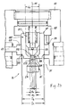
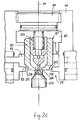
- Stroke control valve 14 which in FIG. 2 in its load-lifting operation assigned functional position I shown is now also supplementary to FIGS. 2a, 2b and 2c Referenced in which the various functional positions I, 0 and II of the stroke control valve 14 assigned Functional positions of a total designated 14 '' Lowering valve unit in relation to the different ones Positions assigned to the functional positions Main piston 14 'are shown.
- the lowering valve unit 14 '' can be preassembled Assembly of the stroke control valve 14 in the housing part 117 integrated on the side of the multi-layer control block 110 is attached and against this by means of the seals 147 and 178 and with another ring seal 179 is sealed in the area of the consumer Connection piece 181 is arranged, which is also on the Housing part 117 is arranged.
- This housing part 117 which is the housing-fixed limit the B-consumer connection chamber 118 is this through an intermediate wall 182 against an outer Deposed pressure chamber 183, which in turn by means of a assembly reasons necessary screw plug 184 is completed pressure-tight to the outside.
- This partition 182 has one with the central longitudinal axis 111 of the Stroke control valve 14 coaxial, central bore 186, in the a cylindrical-pot-shaped "outer" valve body 187 is slidably arranged in a pressure-tight sliding manner.
- This central partition wall bore 186 is slightly larger than the diameter D2 one with this coaxial tank compartment side opening 188 of the housing part 117 formed by an inner annular rib 189 of the sleeve Extension 146 of the housing part 117 is edged, through which the B-consumer connection chamber 118 against the Tank space 54 'is offset by the in the area of Stroke control valve 14 extending portion of the return line 54 is formed.
- connection chamber 191 of the opening 188 bordered by the annular rib 189 forms a circular valve seat for the cup-shaped Valve body 187 with a circular cone Sealing surface 192, over which an outer cylindrical outer surface 193 to the bottom area 194 of the valve body 187 connects, can be supported on the valve seat 191.
- the valve body bottom 194 whose tank space-side boundary surface 196 extends radially within the conical sealing surface area 192 at right angles to the central longitudinal axis 111 and whose inner boundary surface 197 in the central bottom region close to the axis also runs at right angles to the central longitudinal axis 111, has a central opening 198 in this area, the diameter of which d 1 is significantly smaller than the inner diameter d 2 of the nevertheless relatively thick-walled cylinder jacket 199 of the valve sleeve-shaped valve body 187.
- the inner circular edge 201 forms the seat for a dome-shaped or frustoconical as shown Sealing body 202 of a second valve body 203 of the lowering valve unit 14 ′′, which acts as a stepped piston is formed with its larger diameter Piston stage 204 against the inner lateral surface 206 of the Cylinder shell 199 of the cylindrical pot-shaped valve body 187 is sealed.
- This outside cylindrical Piston stage 204 is in turn cylindrical-cup-shaped, being in communication with the outer pressure chamber 183 Connected interior 207 via a longitudinal channel 209 axially penetrating bottom region 208 and communicating with this transverse channels 211 of the Diameter after smaller piston stage 212, which in the frustoconical Sealing body 202 runs out with the the two valve bodies 187 and 203 bordered inner annulus 213 of the lowering valve unit 14 ′′ in constantly communicating Connection is established.
- the - annular space - consumer connection chamber 118 is via a fixed throttle 217 with the outer pressure chamber 183 in constantly communicating connection, so that in the in the 2 and 2a shown, locking configuration of the Lowering valve unit 14 ′′ in the outer pressure chamber 183 the same pressure as in the B-consumer connection chamber 118.
- throttle 217 which in the 2 and 2a as a stepped bore parallel to the central Longitudinal axis 111 of the stroke control valve 14 extending central Axis 218 is shown, corresponding throttle could also, as indicated by dashed lines, by a narrow longitudinal groove 217 'shallow radial depth of the outer Valve body 187 of the lowering valve unit 14 '' or a corresponding longitudinal groove 217 ′′ of the central bore 186 the intermediate wall 182 of the lowering valve unit 14 ′′ receiving housing part 117 can be realized.
- the housing part 117 containing the lowering valve unit 14 ′′ which must be prefabricated as a separate part from the control block 110 in the exemplary embodiment of the hydraulic installation 10 selected for explanation, can be described in detail in the structure of the control block 110 Layering technique explained can be composed of segment sheets 1171 to 11710 of different thicknesses if necessary, for which a possible division is indicated by dashed-line solder joints 220 (FIG. 2a), with the choice of which only minor and simple preprocessing of the segment sheets 117 4 , 177 5 and 117 6 are required before the segment sheet package 117 1 to 117 10 forming the housing part 117 can be soldered together.
- the overall configuration of the arrangement shown in FIG. 2 of the motor-controlled main piston 14 ', the valve body 187 and 203 of the lowering valve unit 14 '' of Stroke control valve 14, the piston 84 of the pressure compensator 79, the Valve body 151 of the check valve 73, the valve ball 221 of the shuttle valve 14 associated with the stroke control valve 72 and the valve ball 222 of the tilt control valve 33 assigned shuttle valve 68 corresponds to a stationary Operating state of the hydraulic installation 10, in which the piston 13 of the stroke drive cylinder 11 with constant Speed in load-lifting mode moved up, while the other hydraulic drives 19, 26 and 28 have stopped, i.e. the control valves assigned to them 33, 34 and 36 in their blocking basic positions 0 are held.
- the motor-driven is in the above-mentioned stationary operating state Main piston 14 'so far from its spring centered Middle position - away from the lowering valve unit 14 '' - disengaged that an annular groove 223 of the piston 14 ', the 128 between the central piston flange and its piston chamber-side piston flange 127 arranged is and in every possible position of the motor-driven Piston 14 'in communication with the pressure (P) supply line 49 Connection is established via the now released Throttle gap 152 also with the A consumer connection 63 is communicatively connected and pressure medium over this and the one opened against the action of its valve spring Check valve 73 in the drive pressure chamber 12 of the stroke drive cylinder 11 can flow.
- the flow path required in this regard which corresponds to the reference pressure connection 81 in the circuit diagram in FIG. 1, is through a transverse channel 224 which is in constant communication with the pressure (P) pressure supply line 49 and also with this and with the reference pressure chamber 89 of the pressure compensator 79 formed in constantly communicating longitudinal channel 226 of the pressure compensator piston 84.
- the pressure compensator piston 84 Due to the positive pressure difference ⁇ p between the reference pressure p R coupled into the reference pressure chamber 89 in the stationary operating state and the operating pressure p B coupled into the operating pressure chamber 88 of the pressure compensator 79, the pressure compensator piston 84 has an equilibrium position deflected against the restoring force of the balance spring 93 with respect to its basic position, in which a throttle gap 229 is released between a piston-side control edge 227 and a housing-side control edge 228 of the control block 110, via which pressure medium can flow back from the pressure (P) supply line 49 to the unpressurized tank space 54 ′ or to the reservoir 56 of the pressure supply unit 52.
- the pressure p B prevailing in the drive pressure chamber 12 of the stroke drive cylinder 11 is also coupled into the B consumer connection chamber and prevails - in the stationary operating state - also in the outer pressure chamber 183 of the lowering valve unit 14 '', the valve bodies 187 and 203 of which are thereby additionally Force against their associated valve seats 191 and 201 are pushed.
- the main piston 14 ′ of the stroke control valve 14, controlled by means of the stepping motor 96 is set to the basic position 0, in which, due to the position of the main piston 14 ′, the pressure (P) supply line 49 is shut off from the a consumer terminal 63, this, however, 128 of the main piston and that arranged adjacent the edge 126 '12 due to a shared in this basic position gap between the central flange at the central longitudinal axis 111 of the lift control valve 14 coaxial recess 126 12 of the segment plate 122 12 of the control block 110 released annular gap with the unpressurized return (T) connection 48 is in communicating connection.
- P pressure
- the stroke control valve 14 is expediently motor-controlled, controlled by the electronic control unit 103 to ensure that the lifting platform gently runs in to ensure the standstill and unwanted vibrations or to avoid vibrations.
- the necessary for this Load information is characteristic of the pressure Output signal of the pressure sensor 107 provided.
- the stop surface 233 'for the support ring 233 of the motor-side valve spring 17 is formed by a radial inner shoulder of the housing part 119, which forms the housing-fixed boundary of the tank connection chamber 121, within which the spindle drive 94 for driving coupling of the stepping motor 96 to the main piston 14' is arranged ;
- the stop surface 234 ', on which - in the basic position 0 of the main piston 14' - the support ring 232 is supported, on which the other valve spring 18, which is arranged in the tank space 54 ', acts on the inner ring rib 189 of the lowering valve unit 14'' Housing part 117 is supported, is formed by the tank chamber side edge of the circular opening 1268 coaxial with the central longitudinal axis 111 of the stroke control valve 14 of the segment plate 122 8 which delimits the tank chamber 54 'from the pressure (P) supply line 49.
- the main piston 14 'of the stroke control valve 14 has on its side facing the lowering valve unit 14''a cylindrical extension 236 passing through the support ring 232 arranged in the tank space 54', the diameter of which is slightly smaller than the inside diameter of the support ring 232.
- This extension tapers over a truncated cone-shaped chamfer 237 to a cylindrical actuating section 238, the diameter d 3 of which is slightly larger than the diameter d 1 of the central opening 198 of the base 194 of the cylindrical cup-shaped valve body 187 of the lowering valve unit 14 ′′.
- This cylindrical actuation section 238 is followed by a slender, tappet-shaped end section 239, the diameter d 4 (FIG. 2b) of which is significantly smaller than the diameter d1 of the central bottom opening 198 of the cup-shaped valve body 187.
- Pressure medium in the drive pressure chamber 12 of the stroke drive cylinder 11 under one supported by the piston 13 Load and by which the drive pressure chamber 12 is movable limiting piston area is certain pressure can now via the B consumer connection 64, the B consumer connection chamber 118, the fixed throttle 217, the outer pressure chamber 183 of the housing part 117, the interior 207, the Longitudinal channel 209 and the transverse channels 211 in the inner annulus 213 of the piston arrangement 187, 203 and now released valve gap 242 (Fig. 2b) in the unpressurized Tank space 54 'of the stroke control valve 14 and via this to Outflow the reservoir 56 of the pressure supply unit 52, with the result that the lift of the forklift is lowered becomes.
- valve gap 242 is significantly smaller than the free flow cross section of the throttle 217, that is Sinking speed essentially due to the throttling effect of the inner seat valve 201, 203 at the given Load determined and by motor-controlled adjustment the valve gap width can be selected.
- the throttling effect of valve gap 242 is significantly smaller than that of the fixed throttle 217 is at a given load the lowering speed by the fixed throttle 217 determined and limited to a load-dependent maximum value.
- the load to be lowered is comparatively low and consequently also the pressure under which the hydraulic medium in the drive pressure chamber 12 of the stroke drive cylinder 11 stands, with the possible consequence that the only by Opening of the pre-relief valve 201, 203 achievable lowering speed would be undesirably low, the effective outflow cross-section of the lowering valve unit 14 '' can be enlarged by further deflection of the main piston 14 'also the further, through the cup-shaped Valve body 187 and the associated Valve seat 191 formed valve of the lowering valve unit 14 '' is opened and thereby the qualitatively in 2c shows the configuration of the valve body 187 and 203 is reached in the print medium from both the by the two valve bodies 187 and 203 bordered annulus 213 as well as the outer one, by lifting the Cup-shaped valve body 187 from the valve seat 191 released valve gap 243 directly from the B consumer connection chamber 118 flow into the unpressurized tank space 54 ' can.
- the cylindrical actuating section 238 of the piston extension 236 is on its level with the tank side Boundary surface 196 of the valve body bottom 194 in Provide notches 244 on the end face reaching the system, then also via the pressure medium from the annular space 213 can flow out sufficiently freely if the cylindrical Actuation section 238 at which the central bottom opening 198 surrounding edge area is supported.
Landscapes
- Engineering & Computer Science (AREA)
- Mechanical Engineering (AREA)
- General Engineering & Computer Science (AREA)
- Fluid Mechanics (AREA)
- Physics & Mathematics (AREA)
- Transportation (AREA)
- Structural Engineering (AREA)
- Life Sciences & Earth Sciences (AREA)
- Geology (AREA)
- Civil Engineering (AREA)
- Chemical & Material Sciences (AREA)
- Combustion & Propulsion (AREA)
- Fluid-Pressure Circuits (AREA)
- Forklifts And Lifting Vehicles (AREA)
Applications Claiming Priority (2)
| Application Number | Priority Date | Filing Date | Title |
|---|---|---|---|
| DE19716442A DE19716442A1 (de) | 1997-04-20 | 1997-04-20 | Hydraulik-Installation an einem Gabelstapler-Fahrzeug |
| DE19716442 | 1997-04-20 |
Publications (3)
| Publication Number | Publication Date |
|---|---|
| EP0872446A2 true EP0872446A2 (fr) | 1998-10-21 |
| EP0872446A3 EP0872446A3 (fr) | 2000-05-03 |
| EP0872446B1 EP0872446B1 (fr) | 2003-10-22 |
Family
ID=7827041
Family Applications (1)
| Application Number | Title | Priority Date | Filing Date |
|---|---|---|---|
| EP98107020A Expired - Lifetime EP0872446B1 (fr) | 1997-04-20 | 1998-04-17 | Installation hydraulique pour chariot élévateur à fourche |
Country Status (2)
| Country | Link |
|---|---|
| EP (1) | EP0872446B1 (fr) |
| DE (2) | DE19716442A1 (fr) |
Cited By (5)
| Publication number | Priority date | Publication date | Assignee | Title |
|---|---|---|---|---|
| EP0943813B2 (fr) † | 1998-03-16 | 2007-08-15 | Hitachi Construction Machinery Co., Ltd. | Manivelle pour valves de sélection |
| DE102011116113A1 (de) * | 2011-10-15 | 2013-04-18 | Jungheinrich Aktiengesellschaft | Flurförderzeug mit einer Arbeitshydraulik |
| WO2014095240A1 (fr) * | 2012-12-17 | 2014-06-26 | Jungheinrich Aktiengesellschaft | Dispositif de levage hydraulique pour chariot de manutention fonctionnant sur batterie |
| CN112441530A (zh) * | 2019-08-29 | 2021-03-05 | 雷蒙德股份有限公司 | 用于物料搬运车辆的可变液压卸压系统和方法 |
| CN114738346A (zh) * | 2022-03-17 | 2022-07-12 | 浙江海宏液压科技股份有限公司 | 集成进油阀组及叉车 |
Families Citing this family (2)
| Publication number | Priority date | Publication date | Assignee | Title |
|---|---|---|---|---|
| DE19909713A1 (de) | 1999-03-05 | 2000-09-07 | Linde Ag | Steuerventileinrichtung |
| DE102013206319A1 (de) * | 2013-04-10 | 2014-10-16 | Deere & Company | Hubvorrichtung |
Family Cites Families (9)
| Publication number | Priority date | Publication date | Assignee | Title |
|---|---|---|---|---|
| BG37431A1 (en) * | 1983-09-27 | 1985-06-14 | Lazarov | Hydraulic scheme for tipping lifting device of electrocar for high- lifting |
| DE3441946A1 (de) * | 1984-11-16 | 1986-05-28 | Robert Bosch Gmbh, 7000 Stuttgart | Hydraulische steuereinrichtung |
| US5036886A (en) * | 1988-12-12 | 1991-08-06 | Olson Controls, Inc. | Digital servo valve system |
| JPH03159879A (ja) * | 1989-11-20 | 1991-07-09 | Toyota Autom Loom Works Ltd | 産業車両の荷役制御装置 |
| JP2877257B2 (ja) * | 1991-02-05 | 1999-03-31 | 三菱重工業株式会社 | 作業機械の制御装置 |
| DE4140409A1 (de) * | 1991-12-07 | 1993-06-09 | Robert Bosch Gmbh, 7000 Stuttgart, De | Elektrohydraulische steuereinrichtung |
| DE4140408A1 (de) * | 1991-12-07 | 1993-06-09 | Robert Bosch Gmbh, 7000 Stuttgart, De | Elektrohydraulische steuereinrichtung |
| DE4241846C2 (de) * | 1992-12-11 | 1996-09-26 | Danfoss As | Hydraulisches System |
| DE29508394U1 (de) * | 1995-05-19 | 1995-08-03 | Heilmeier & Weinlein Fabrik für Oel-Hydraulik GmbH & Co KG, 81673 München | Elektrohydraulisches Hubmodul |
-
1997
- 1997-04-20 DE DE19716442A patent/DE19716442A1/de not_active Withdrawn
-
1998
- 1998-04-17 DE DE59809944T patent/DE59809944D1/de not_active Expired - Lifetime
- 1998-04-17 EP EP98107020A patent/EP0872446B1/fr not_active Expired - Lifetime
Cited By (6)
| Publication number | Priority date | Publication date | Assignee | Title |
|---|---|---|---|---|
| EP0943813B2 (fr) † | 1998-03-16 | 2007-08-15 | Hitachi Construction Machinery Co., Ltd. | Manivelle pour valves de sélection |
| DE102011116113A1 (de) * | 2011-10-15 | 2013-04-18 | Jungheinrich Aktiengesellschaft | Flurförderzeug mit einer Arbeitshydraulik |
| WO2014095240A1 (fr) * | 2012-12-17 | 2014-06-26 | Jungheinrich Aktiengesellschaft | Dispositif de levage hydraulique pour chariot de manutention fonctionnant sur batterie |
| CN112441530A (zh) * | 2019-08-29 | 2021-03-05 | 雷蒙德股份有限公司 | 用于物料搬运车辆的可变液压卸压系统和方法 |
| CN112441530B (zh) * | 2019-08-29 | 2024-08-27 | 雷蒙德股份有限公司 | 用于物料搬运车辆的可变液压卸压系统和方法 |
| CN114738346A (zh) * | 2022-03-17 | 2022-07-12 | 浙江海宏液压科技股份有限公司 | 集成进油阀组及叉车 |
Also Published As
| Publication number | Publication date |
|---|---|
| EP0872446A3 (fr) | 2000-05-03 |
| DE59809944D1 (de) | 2003-11-27 |
| EP0872446B1 (fr) | 2003-10-22 |
| DE19716442A1 (de) | 1998-10-22 |
Similar Documents
| Publication | Publication Date | Title |
|---|---|---|
| DE60120061T2 (de) | Hydrauliksystem mit gekreuzter Energierückgewinnung | |
| DE10344480B3 (de) | Hydraulische Ventilanordnung | |
| EP0936179B1 (fr) | Systême de commande pour chariot élévateur | |
| EP0546300A1 (fr) | Dispositif de commande électrohydraulique | |
| AT505724A1 (de) | Antriebsvorrichtung für eine biegepresse | |
| DE4320353A1 (de) | Hydraulische Getriebeansteuerung | |
| DE3227630A1 (de) | Hydraulische steueranlage fuer industrielle fahrzeuge | |
| EP2518331A1 (fr) | Dispositif de soupape | |
| EP1065379B1 (fr) | Alimentation en pression avec pompe à capacité variable et motorisation électrique réglable | |
| DE102011011750A1 (de) | Druckspeicherlose hydraulische Antriebsanordnung für und mit einem Verbraucher, insbesondere für Pressen sowie Verfahren zum Betreiben einer solchen druckspeicherlosen hydraulischen Antriebsanordnung | |
| DE102016119823A1 (de) | Elektrohydraulische Antriebseinheit | |
| EP2220467B1 (fr) | Balance | |
| DE3539220C2 (fr) | ||
| EP0872446B1 (fr) | Installation hydraulique pour chariot élévateur à fourche | |
| DE102008025054A1 (de) | Hydraulikeinheit | |
| EP1222416B1 (fr) | Unite soupape de commande pour un ascenseur hydraulique | |
| DE69528600T2 (de) | Bremsvorrichtung für einen hydraulischen motor | |
| EP0561185A1 (fr) | Commande hydraulique de tiroir pour vérins avec des vitesses de piston inégales | |
| EP0219052B1 (fr) | Dispositif de commande hydraulique | |
| DE102016115300A1 (de) | Aktuatoranordnung zum Betätigen einer Stelleinheit in einem Kraftfahrzeug und Kupplungsanordnung mit einer solchen Aktuatoranordnung | |
| EP4413270B1 (fr) | Axe compact hydraulique comprenant une pluralité de composants tubulaires | |
| EP4375228A1 (fr) | Dispositif de levage | |
| DD212770A5 (de) | Steuerventil fuer hydraulische praezisionssteuerungen | |
| DE19505691A1 (de) | Hubvolumen-verstellbares Hydraulikaggregat | |
| DE4120489A1 (de) | Niveauregeleinrichtung fuer fahrzeuge |
Legal Events
| Date | Code | Title | Description |
|---|---|---|---|
| PUAI | Public reference made under article 153(3) epc to a published international application that has entered the european phase |
Free format text: ORIGINAL CODE: 0009012 |
|
| AK | Designated contracting states |
Kind code of ref document: A2 Designated state(s): DE FR GB IT |
|
| AX | Request for extension of the european patent |
Free format text: AL;LT;LV;MK;RO;SI |
|
| PUAL | Search report despatched |
Free format text: ORIGINAL CODE: 0009013 |
|
| AK | Designated contracting states |
Kind code of ref document: A3 Designated state(s): AT BE CH CY DE DK ES FI FR GB GR IE IT LI LU MC NL PT SE |
|
| AX | Request for extension of the european patent |
Free format text: AL;LT;LV;MK;RO;SI |
|
| 17P | Request for examination filed |
Effective date: 20000408 |
|
| AKX | Designation fees paid |
Free format text: DE FR GB IT |
|
| RAP1 | Party data changed (applicant data changed or rights of an application transferred) |
Owner name: HARTMANN + LAEMMLE GMBH & CO. KG |
|
| RIN1 | Information on inventor provided before grant (corrected) |
Inventor name: SCHULZE, ECKEHART |
|
| GRAG | Despatch of communication of intention to grant |
Free format text: ORIGINAL CODE: EPIDOS AGRA |
|
| RAP1 | Party data changed (applicant data changed or rights of an application transferred) |
Owner name: HARTMANN & LAEMMLE GMBH & CO. KG |
|
| 17Q | First examination report despatched |
Effective date: 20020603 |
|
| GRAG | Despatch of communication of intention to grant |
Free format text: ORIGINAL CODE: EPIDOS AGRA |
|
| GRAG | Despatch of communication of intention to grant |
Free format text: ORIGINAL CODE: EPIDOS AGRA |
|
| GRAH | Despatch of communication of intention to grant a patent |
Free format text: ORIGINAL CODE: EPIDOS IGRA |
|
| GRAH | Despatch of communication of intention to grant a patent |
Free format text: ORIGINAL CODE: EPIDOS IGRA |
|
| GRAA | (expected) grant |
Free format text: ORIGINAL CODE: 0009210 |
|
| AK | Designated contracting states |
Kind code of ref document: B1 Designated state(s): DE FR GB IT |
|
| REG | Reference to a national code |
Ref country code: GB Ref legal event code: FG4D Free format text: NOT ENGLISH |
|
| REF | Corresponds to: |
Ref document number: 59809944 Country of ref document: DE Date of ref document: 20031127 Kind code of ref document: P |
|
| GBT | Gb: translation of ep patent filed (gb section 77(6)(a)/1977) |
Effective date: 20031204 |
|
| ET | Fr: translation filed | ||
| PLBE | No opposition filed within time limit |
Free format text: ORIGINAL CODE: 0009261 |
|
| STAA | Information on the status of an ep patent application or granted ep patent |
Free format text: STATUS: NO OPPOSITION FILED WITHIN TIME LIMIT |
|
| 26N | No opposition filed |
Effective date: 20040723 |
|
| PGFP | Annual fee paid to national office [announced via postgrant information from national office to epo] |
Ref country code: FR Payment date: 20060313 Year of fee payment: 9 |
|
| PGFP | Annual fee paid to national office [announced via postgrant information from national office to epo] |
Ref country code: IT Payment date: 20060430 Year of fee payment: 9 |
|
| GBPC | Gb: european patent ceased through non-payment of renewal fee |
Effective date: 20070417 |
|
| PG25 | Lapsed in a contracting state [announced via postgrant information from national office to epo] |
Ref country code: GB Free format text: LAPSE BECAUSE OF NON-PAYMENT OF DUE FEES Effective date: 20070417 |
|
| PG25 | Lapsed in a contracting state [announced via postgrant information from national office to epo] |
Ref country code: FR Free format text: LAPSE BECAUSE OF NON-PAYMENT OF DUE FEES Effective date: 20070430 |
|
| PGFP | Annual fee paid to national office [announced via postgrant information from national office to epo] |
Ref country code: GB Payment date: 20060316 Year of fee payment: 9 |
|
| PG25 | Lapsed in a contracting state [announced via postgrant information from national office to epo] |
Ref country code: IT Free format text: LAPSE BECAUSE OF NON-PAYMENT OF DUE FEES Effective date: 20070417 |
|
| PGFP | Annual fee paid to national office [announced via postgrant information from national office to epo] |
Ref country code: DE Payment date: 20110423 Year of fee payment: 14 |
|
| REG | Reference to a national code |
Ref country code: DE Ref legal event code: R119 Ref document number: 59809944 Country of ref document: DE Effective date: 20121101 |
|
| PG25 | Lapsed in a contracting state [announced via postgrant information from national office to epo] |
Ref country code: DE Free format text: LAPSE BECAUSE OF NON-PAYMENT OF DUE FEES Effective date: 20121101 |