EP0872603A2 - Kombiniertes Vakuum-Toilettensystem sowie An- BZW. Abkopplungsvorrichtung - Google Patents
Kombiniertes Vakuum-Toilettensystem sowie An- BZW. Abkopplungsvorrichtung Download PDFInfo
- Publication number
- EP0872603A2 EP0872603A2 EP98106821A EP98106821A EP0872603A2 EP 0872603 A2 EP0872603 A2 EP 0872603A2 EP 98106821 A EP98106821 A EP 98106821A EP 98106821 A EP98106821 A EP 98106821A EP 0872603 A2 EP0872603 A2 EP 0872603A2
- Authority
- EP
- European Patent Office
- Prior art keywords
- tank
- pipe socket
- vacuum pump
- coupling
- platform
- Prior art date
- Legal status (The legal status is an assumption and is not a legal conclusion. Google has not performed a legal analysis and makes no representation as to the accuracy of the status listed.)
- Granted
Links
Images



Classifications
-
- E—FIXED CONSTRUCTIONS
- E03—WATER SUPPLY; SEWERAGE
- E03F—SEWERS; CESSPOOLS
- E03F1/00—Methods, systems, or installations for draining-off sewage or storm water
- E03F1/006—Pneumatic sewage disposal systems; accessories specially adapted therefore
-
- B—PERFORMING OPERATIONS; TRANSPORTING
- B60—VEHICLES IN GENERAL
- B60R—VEHICLES, VEHICLE FITTINGS, OR VEHICLE PARTS, NOT OTHERWISE PROVIDED FOR
- B60R15/00—Arrangements or adaptations of sanitation devices
- B60R15/04—Toilet facilities
-
- E—FIXED CONSTRUCTIONS
- E03—WATER SUPPLY; SEWERAGE
- E03D—WATER-CLOSETS OR URINALS WITH FLUSHING DEVICES; FLUSHING VALVES THEREFOR
- E03D5/00—Special constructions of flushing devices, e.g. closed flushing system
-
- Y—GENERAL TAGGING OF NEW TECHNOLOGICAL DEVELOPMENTS; GENERAL TAGGING OF CROSS-SECTIONAL TECHNOLOGIES SPANNING OVER SEVERAL SECTIONS OF THE IPC; TECHNICAL SUBJECTS COVERED BY FORMER USPC CROSS-REFERENCE ART COLLECTIONS [XRACs] AND DIGESTS
- Y10—TECHNICAL SUBJECTS COVERED BY FORMER USPC
- Y10T—TECHNICAL SUBJECTS COVERED BY FORMER US CLASSIFICATION
- Y10T137/00—Fluid handling
- Y10T137/402—Distribution systems involving geographic features
-
- Y—GENERAL TAGGING OF NEW TECHNOLOGICAL DEVELOPMENTS; GENERAL TAGGING OF CROSS-SECTIONAL TECHNOLOGIES SPANNING OVER SEVERAL SECTIONS OF THE IPC; TECHNICAL SUBJECTS COVERED BY FORMER USPC CROSS-REFERENCE ART COLLECTIONS [XRACs] AND DIGESTS
- Y10—TECHNICAL SUBJECTS COVERED BY FORMER USPC
- Y10T—TECHNICAL SUBJECTS COVERED BY FORMER US CLASSIFICATION
- Y10T137/00—Fluid handling
- Y10T137/8593—Systems
- Y10T137/87917—Flow path with serial valves and/or closures
- Y10T137/87925—Separable flow path section, valve or closure in each
- Y10T137/87941—Each valve and/or closure operated by coupling motion
- Y10T137/87949—Linear motion of flow path sections operates both
-
- Y—GENERAL TAGGING OF NEW TECHNOLOGICAL DEVELOPMENTS; GENERAL TAGGING OF CROSS-SECTIONAL TECHNOLOGIES SPANNING OVER SEVERAL SECTIONS OF THE IPC; TECHNICAL SUBJECTS COVERED BY FORMER USPC CROSS-REFERENCE ART COLLECTIONS [XRACs] AND DIGESTS
- Y10—TECHNICAL SUBJECTS COVERED BY FORMER USPC
- Y10T—TECHNICAL SUBJECTS COVERED BY FORMER US CLASSIFICATION
- Y10T137/00—Fluid handling
- Y10T137/8593—Systems
- Y10T137/87917—Flow path with serial valves and/or closures
- Y10T137/87925—Separable flow path section, valve or closure in each
- Y10T137/87965—Valve- or closure-operated by coupling motion
Definitions
- the invention relates to a device for automatic liquid and / or gas-tight coupling or uncoupling of a container to a line, in particular a mobile tank to a connection line of a toilet system.
- the invention also relates to a combined vacuum toilet system for a stationary or a mobile device, especially weekend houses, construction containers or mobile homes, caravans, boats and / or the like.
- a liquid and / or gas-tight connection or Decoupling the tank from the system is also particularly desirable if the tank works as a vacuum tank in a vacuum toilet system because that Vacuum in the tank must be maintained during connection. Leakage would cause the vacuum pump to run continuously would be so that the energy resources of the caravan or boat or the like are quickly exhausted would be. On the other hand, a permanently running vacuum pump would be too lead to high energy consumption even in network operation and beyond to a nuisance as a result of noise.
- the invention is therefore based on the object of a device for simple liquid and / or gas-tight coupling or uncoupling of a container a line, in particular a mobile tank to a connecting line of a To create toilet systems, the connection when inserting the Tanks is generated as automatically as possible.
- the invention is also the Task, a vacuum toilet system for a stationary facility or a mobile vehicle, especially weekend houses or mobile homes, To create caravans, boats or the like, in which by a suitable connecting device guaranteed between the tank and the vacuum toilet is that the vacuum in the toilet system or the tank as long as possible is maintained as long as the toilet is not in use, so that Connection must be highly gas and / or liquid tight and above also easy coupling and uncoupling to the vacuum toilet system is guaranteed.
- Each flange has at least one in the coupling position in Cover to bring together opening through which a connection of the toilet can be made into a tank.
- the connection between separate from the toilet system and the tank it is provided that locking parts in a respective flange during the decoupling movement move to a closed position in which the respective opening is closed becomes.
- the flanges are advantageously formed by pipe sockets, one of which is a pipe socket is closed at its front end, while the other pipe socket can be closed by the sliding part mounted in it. Will the pipe socket is therefore pushed into each other, so the socket with the Larger outside diameter the closure piece, which on the nozzle with the smaller outer diameter is slidable, from the closed position move to the open position while the nozzle with the smaller one Diameter the closure piece, which is in the socket with the larger Diameter is mounted sliding, in turn from the closed position shifts the open position.
- the pipe sockets are dimensioned in this way and arranged to each other that the mutually aligned openings that are advantageously located in the outer surface of the pipe socket, in the coupling position cursed inside the tank room.
- the Closure parts can be adapted to the shape of the pipe socket, preferably cylindrical slides with end flanges, which are formed serve as a contact surface. These slides give the openings in the coupling position free or close in the decoupled position.
- the Slider advantageously in the closing direction by springs, preferably Coil springs biased to ensure that the slider always move automatically into the closed position when the tank is uncoupled, in which they close the respective opening.
- the sealants are included advantageously formed by O-ring seals, which are in the closed position located in front of and behind the opening.
- the slide further sealing means may be provided. So that the slider do not twist when moving and thus limit their longitudinal movement tongue and groove devices are advantageously provided, in which the slides are guided. These tongue and groove devices also prevent the slider from rotating about its longitudinal axis.
- the valve on the tank side is a piston-like hollow body, the pushed against the action of a spring action in the open position is, the spring on a front closure of the tank side Supports pipe socket. Since it is when inserting the slide in the front sealed tank pipe socket to compress the contained therein Air could come, the piston has a vent hole, so that the air contained in it via a further opening in the pipe socket into the tank space can escape.
- each pipe socket two openings are advantageously provided are arranged diametrically to each other, with a smaller opening at the top and a larger opening is provided on the underside of the respective nozzle are.
- the toilet system is a vacuum toilet system with one Vacuum pump, then there are different ways to vacuum the tank maintain.
- the first embodiment is vacuum line and fecal line united in the platform-side pipe socket, although both Pipes through a spanning most of the length of the pipe socket extending partition are separated from each other.
- the slightly smaller upper one Chamber is connected on the one hand to the vacuum pump and on the other hand in the Coupling position via the upper smaller opening with the tank interior, while the slightly larger chamber is connected to the toilet and further in the coupling position via the slightly larger openings pointing downwards with the tank interior. This ensures that over the vacuum pump can not suck feces, but in the The tank only creates the vacuum to keep the feces out of the toilet area can be sucked into the tank.
- the vacuum suction line from the faecal line is arranged separately, the vacuum line over one another Slidable, gas and liquid-tight sealed in the coupling position Pipe socket system directly connected to an upper area of the tank can be so that it occupies an elevated position in the tank for suction to exclude faeces.
- Pipe socket system directly connected to an upper area of the tank can be so that it occupies an elevated position in the tank for suction to exclude faeces.
- appropriate coupling or decoupling systems are provided for both the vacuum line and the faecal line, similar to that described above.
- the vacuum pump is attached to the wall of the platform and is more advantageous Way driven by a drive motor, in particular an electric motor.
- a sensor for tank detection detects the level of the tank and shows it depending on a certain level reached.
- This sensor is preferably in the wall of the platform in the area below the openings for arranged the entry of the faeces into the tank.
- a sensor for Detection of the negative pressure prevailing in the tank is provided. All sensors are operatively connected to switches which control the flow of energy to the drive motor interrupt or release the vacuum pump if predetermined Target values or states are exceeded or undershot or recorded. Is e.g. If no tank is inserted, the power supply to the drive motor is interrupted. When the filling level is reached, the power supply is interrupted. Respectively. the specified vacuum is reached, the vacuum pump is switched off, etc.
- the bottom part has a housing-like frame, which is equipped with guiding devices, especially on its upper side is, which can be brought into engagement with corresponding devices in the tank bottom to hold the tank in the docking position and even at Vehicle movements to ensure that the tank does not move can.
- Locking means can be provided on the tank and / or the base part, with which the tank can be locked in the coupling position. These locking devices can be designed in such a way that they are easily released for removal of the tank can be.
- the frame-like bottom part has a receptacle for a replaceable one Filter device, which advantageously with its inlet to the exhaust side the vacuum pump and with its outlet to one into the free atmosphere opening hose connection is connected.
- the filter device can be spring-loaded in the inserted position and an activated carbon filter included, which is easily exchangeable for a new filter cassette is.
- the tank Since the tank is mainly used in mobile vehicles and for temporary use The feces are collected, which are then filled at a corresponding tank Disposal station are disposed of, it is appropriate that the Tank is designed to be manageable. So he z. B. appropriate handles and may also have rolling support elements that pull out facilitate the guide device of the bottom part. Finally, it is more advantageous Way provided that the tank from the outside of the caravan through a lockable opening is accessible.
- the combined vacuum toilet system besides the advantages described above, the light Manageability, hygiene and low odor nuisance Advantage that the addition of chemicals is essentially avoided can, since the vacuum system prevents unpleasant odors. This contributes to considerable measures to relieve the burden on the environment.
- the platform-side coupling system 1 is in a schematic Longitudinal section shown. From a platform 2 with a foot part 3 screwed to the floor 4 of a vehicle or a stationary device and can be a vertical wall 5 supported by lateral cheeks 6, 7 has, a pipe socket 8 is held, which is on both sides of the wall 5 extends to the left and right in relation to FIG. 1. At the in Fig. 1st left end of the pipe socket 8 is the connecting line 9 using a Seal 10 connected sealingly, this connecting line 9 a Connects to the toilet system and in the area of the toilet bowl is closed by a corresponding valve device.
- the right part with respect to FIG. 1 of the pipe socket 8 extends into a with dash-dotted lines schematically indicated tank 11, in which the feces coming from the toilet are to be collected, as later will be described in detail.
- tank 11 is in its Coupling position pushed close to the wall 5 and is in this position fixed by appropriate locking means, which later is still received.
- the front right end of the pipe socket 8 is closed by a cover 12.
- the upper opening 13 is a substantial has a smaller diameter than the lower opening 14.
- two O-ring seals 15, 16 are provided, which in corresponding ring grooves in the outer surface of the pipe socket 8 arranged are.
- the openings 13, 14 can be closed by a closure part 17, which as cylindrical slide is formed with a front flange 18 and on the lateral surface of the pipe socket 8 is slidably mounted.
- the slide takes in 1, in which the tank 11 is not connected to the pipe socket 8, his locking position in which he with one in two grooves 19, 20 in the Shell surface of the pipe socket 8 guided stop 21 to the right end the groove 20 is moved.
- the slide 17 is by means of a Coil spring 22 held with its left end on the wall 5 of the Platform 2 and supported with its right end on the flange 18 of the slide.
- the slide 17 In order to move the slide 17 to its left open position, the right end face of the flange 18 a compressive force is exerted Slide against the spring force of the spring 22 to the left until the openings 13 and 14 are exposed.
- the slide is moved by a or more stops 21 and the grooves 19, 20 limited.
- the stops 21 can e.g. B. of adjustable grub screws in through holes the lateral surface of the slide are screwed in, be formed.
- the attacks 21 not only limit the movement of the slide to the left and right, but also prevent rotation of the slide around the pipe axis.
- the partition 23 is arcuate formed and at its end facing the connecting line 9 closed by an end wall 26. This way, an upper one becomes smaller Annular chamber 24 and a lower larger chamber 25 are formed.
- On the side of the Chamber 24 connects to a nozzle 27 to which a vacuum pump 28 is connected is that can be driven by an electric motor 29.
- the vacuum pump 28 is only shown schematically in FIG. 2 and is made by means of the mounting devices 30 held on the wall 5.
- the electric motor 29 profiles 31, 32 formed on the wall can be provided.
- the platform and the pipe socket 8 can be made from a one-piece plastic part by injection molding be made.
- FIG. 3 is a further pipe socket 34 in an enlarged to FIG. 1 Scale shown, which is also cylindrical and on his left end has a flange 35 and at its right front end is closed by a lid 36.
- the inside diameter 37 of the pipe socket 34 corresponds almost to the outer diameter of the pipe socket 8, so that the pipe socket 8 can be pushed into the pipe socket 34 and in this can be added smoothly.
- the ones described above take care of this O-ring seals 15, 16 for a corresponding seal between the O-rings lying ring space.
- the pipe socket 34 has an upper smaller opening 13 'and a lower one larger opening 14 ', which in its diameter and arrangement exactly the Openings 13 and 14 correspond and 8 in when inserting the pipe socket the pipe socket 34 can be brought into coincidence with one another, as is shown in FIG. 4 is shown.
- the insertion movement of the pipe socket 8 into the pipe socket 34 can be either by a on the wall 5 of the platform 2 Stop or an insertion limit can be effected.
- the openings 13, 13 'and 14, 14' aligned with each other and within of the tank 11 are arranged.
- the pipe socket 34 is in an annular flange 38 added, which has an end flange portion 39.
- This ring flange 38 is dash-dotted in a corresponding opening indicated tank wall 40 of the tank 11 used to an enlarged To offer recording for the pipe socket 34.
- the flange portion 39 is below Storage of a seal 41 with the aid of screws 42 with the flange 25 connected.
- the tank is e.g. B. for emptying from the Vehicle has been removed.
- the openings 13 'and 14 ' closed by a slide 43, the outer diameter of which almost Inner diameter of the pipe socket 34 corresponds.
- the Slider grooves 44, 45 are provided, in which O-ring seals 46, 47 are arranged. In this way, the slider is in the position shown 43 the openings 13 'and 14' are closed in a liquid-tight and gas-tight manner.
- the left-hand closing movement of the slide 43 is determined by a step-shaped limiting device 48, which is limited in a corresponding Groove 49 is movable, which in the longitudinal direction of the pipe socket 34 whose inner surface is located.
- a step-shaped limiting device 48 which is limited in a corresponding Groove 49 is movable, which in the longitudinal direction of the pipe socket 34 whose inner surface is located.
- the slider 43 is a piston-shaped hollow body with a right open one End formed in which a coil spring 50 is received.
- the Coil spring is supported on the one hand on the piston crown 51 and on the other hand on Cover 36 and holds the slide 43 in the closed position, so that in the Tank-absorbed liquid or faeces or the like. Drip-proof and odor-proof be kept.
- There is a separate one for emptying the tank Opening provided with a connection, not shown, by a suitable Closure device is closable.
- the coupling or docking position is shown, in which the Pipe socket 8 is inserted into the pipe socket 34 so far that the openings 13, 13 'and 14, 14' are arranged to cover one another.
- the tank 11 bumps with his front tank wall 53 against a corresponding stop of the vertical Wall 5 of platform 2. Not shown in the wall 5 Contacts or sensors register that the tank is in its coupling position is moved, and enable the operation of the vacuum pump.
- a Also not shown sensor may be provided in the wall 5, the degree of filling of the tank 11 detected, and finally a sensor for detecting the Pressure condition provided in the tank. All sensors are in with switches Active connection, which the energy flow to the drive motor of the vacuum pump interrupt or release if predetermined setpoints or states exceed or fall below or be recorded. Is e.g. no tank installed, the power supply to the drive motor is interrupted. Is the level reached, the power supply is interrupted. Respectively. is the given vacuum reached, the vacuum pump is switched off, etc.
- an air flow 33 through the openings 13, 13 ', the air chamber 24 and the Sockets 27 are sucked out of the tank interior 11 by means of the vacuum pump 28 be so that in the tank 11 and via the connection of the openings 14, 14 'and the fecal chamber 25 up to the toilet forms a vacuum. If the toilet is now used and a corresponding valve at the lower end the toilet bowl is opened, then the faeces are removed via the chamber 25 sucked through the openings 14, 14 'into the tank 11.
- the vacuum is sufficient to aspirate all the fecal matter so that after actuation the toilet, the chamber 25 is completely free of faeces. Building a new vacuum is created intermittently by the vacuum pump. Because the openings 13, 13 'and 14, 14' arranged diametrically opposite one another are avoided in an advantageous manner that feces from the tank through the vacuum pump are sucked in.
- a further advantageous embodiment can also be provided be that separate pipe sockets for the faecal line and the air line are provided, the pipe socket for the air flow as possible in a very high area of the tank 11 is arranged.
- the tank would be in such a case equipped with two sockets into which the corresponding Neck of the platform 2 would be insertable when coupling the tank a connection via corresponding openings to the vacuum pump or to Manufacture toilet.
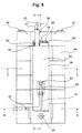
- FIG. 1 Bottom part 54 reached, as shown in Fig. 5 in plan view.
- the bottom part 54 is formed by a housing-like frame on its top is equipped with guide devices 55.
- On its vertical Centering hooks 56, 57 are provided on wall 5 of the end face facing the platform, which can be hooked into recesses in the wall 5, around the base part to fix the wall 5.
- the tank 11 has corresponding recesses and on its underside Guides that can be brought into engagement with the guide device 55.
- the bottom part 54 Since the bottom part 54 is no longer removed from the caravan after it has been installed , it is attached to the centering hook by means of a fastening device 58 56, 57 opposite end fixed to the bottom of the caravan.
- the tank can have latching means on its end face facing away from the wall 5 have which engage in corresponding recesses in the frame part 54, when the tank is in its docking position.
- latching means on its end face facing away from the wall 5 have which engage in corresponding recesses in the frame part 54, when the tank is in its docking position.
- it can z. B. act as a slidable plate in the vertical direction Tank is guided and by gravity or by hand Pushing force slides down to fit into a matching recess in the bottom part 54 to engage under friction.
- the bottom part 54 has in its middle Area of a receptacle 59 or depression in which a filter device 60 can be used.
- the filter device is an activated carbon filter, which has an inlet 61 and an outlet 62.
- the inlet 61 is under Use of an O-ring seal 63 inserted into a flange 64, which on a Spring plate 65 is attached and in which a nozzle 66 engages.
- the exhaust line 67 from the vacuum pump is connected to the nozzle.
- compression springs 68 Between the spring plate 65 and the edge of the receptacle 59 are compression springs 68 arranged, which ensure that the filter device 60 under a certain Bias is held in the receptacle 59.
- the outlet 62 of the filter device 60 picks up and in turn connected to a hose 70 is that leads to the free atmosphere.
Landscapes
- Engineering & Computer Science (AREA)
- Public Health (AREA)
- Health & Medical Sciences (AREA)
- Water Supply & Treatment (AREA)
- Hydrology & Water Resources (AREA)
- Life Sciences & Earth Sciences (AREA)
- Aviation & Aerospace Engineering (AREA)
- Epidemiology (AREA)
- General Health & Medical Sciences (AREA)
- Mechanical Engineering (AREA)
- Vehicle Waterproofing, Decoration, And Sanitation Devices (AREA)
- Sanitary Device For Flush Toilet (AREA)
- Quick-Acting Or Multi-Walled Pipe Joints (AREA)
Abstract
Description
- Fig. 1
- eine schematische Längsschnittansicht durch das plattformseitige Ankopplungssystem;
- Fig. 2
- eine Stirnseitenansicht in Richtung des Pfeils A;
- Fig. 3
- den tankseitigen Rohrstutzen mit dem darin gelagerten Schieber;
- Fig. 4
- eine schematische Darstellung der Ankopplungssituation des tankseitigen Rohrstutzens und des plattformseitigen Rohrstutzens;
- Fig. 5
- eine Draufsicht auf die Bodeneinheit;
- Fig. 6
- eine Längsschnittansicht entlang der Linie A-A in Fig. 5, und
- Fig. 7 und 8
- Schnittansichten entlang der Linien B-B bzw. C-C in Fig. 5.
- 1
- plattformseitiges Ankopplungssystem
- 2
- Plattform
- 3
- Fußteil
- 4
- Boden
- 5
- senkrechte Wand
- 6, 7
- Wange
- 8
- Rohrstutzen
- 9
- Verbindungsleitung
- 10
- Dichtung
- 11
- Tank
- 12
- Deckel
- 13, 13'
- obere kleinere Öffnung
- 14, 14'
- untere größere Öffnung
- 15, 16
- O-Ringdichtung
- 17
- Verschlußteil, Schieber
- 18
- Flansch
- 19, 20
- Nut
- 21
- Anschlag
- 22
- Schraubenfeder
- 23
- Trennwand
- 24
- Luftkammer
- 25
- Fäkalienkammer
- 26
- Kammerstirnwand
- 27
- Stutzen
- 28
- Vakuumpumpe
- 29
- Elektromotor
- 30
- Montageeinrichtung
- 31, 32
- Profile
- 33
- Luftstrom
- 34
- Rohrstutzen
- 35
- Flansch
- 36
- Deckel
- 37
- Innendurchmesser
- 38
- Ringflansch
- 39
- Flanschabschnitt
- 40
- Tankwand
- 41
- Dichtung
- 42
- Schrauben
- 43
- Schieber
- 44, 45
- Ringnut
- 46, 47
- O-Ringdichtung
- 48
- Begrenzungseinrichtung
- 49
- Nut
- 50
- Schraubenfeder
- 51
- Kolbenboden
- 52
- Entlüftungsbohrung
- 53
- vordere Tankwand
- 54
- Bodenteil
- 55
- Führungseinrichtung
- 56, 57
- Zentrierhaken
- 58
- Befestigungseinrichtung
- 59
- Aufnahme
- 60
- Filtereinrichtung
- 61
- Einlaß
- 62
- Auslaß
- 63
- O-Ringdichtung
- 64
- Flansch
- 65
- Federplatte
- 66
- Stutzen
- 67
- Abluftleitung
- 68
- Druckfedern
- 69
- Stutzen
- 70
- Schlauch
Claims (38)
- Vorrichtung zum selbsttätigen flüssigkeits- und/oder gasdichten An- bzw. Abkoppeln eines Behälters an eine Leitung, insbesondere eines mobilen Tanks (11) an eine Verbindungsleitung (9) eines Toilettensystems,
dadurch gekennzeichnet, daßdas Kopplungsende der Leitung (9) und der anzukoppelnde Tank (11) je einen Flansch (8, 34) aufweisen, die in eine abgedichtete Position zueinander bewegbar sind,daß jeder Flansch (8, 34) wenigstens eine in der Kopplungsstellung in Deckung zueinander bringbare Öffnung (13, 13', 14, 14') aufweist, durch welche eine Verbindung zwischen dem Toilettensystem und dem Tank (11) herstellbar ist, unddaß jede Öffnung in der entkoppelten Position durch ein sich beim Entkoppeln in eine Verschlußstellung bewegbares Verschlußteil (17, 43) verschlossen ist. - Vorrichtung nach Anspruch 1, dadurch gekennzeichnet, daß die Flansche (8, 34) unter Zwischenlagerung von Dichtungsmitteln (15, 16) ineinander schiebbar sind, bis die Öffnungen (13, 13', 14, 14') innerhalb des Tanks (11) fluchten.
- Vorrichtung nach Anspruch 1, dadurch gekennzeichnet, daß die Flansche (8, 34) von Rohrstutzen gebildet sind, von denen einer (8) an seinem stirnseitigen Ende verschlossen ist, während der andere (34) an seinem stirnseitigen Ende durch das Verschlußteil (43) verschließbar ist, und daß die Öffnungen (13, 13', 14, 14') in der Mantelfläche der Rohrstutzen (8, 34) angeordnet sind.
- Vorrichtung nach wenigstens einem der vorhergehenden Ansprüche, dadurch gekennzeichnet, daß das Kopplungsende der Leitung (9) und der Tank (11) in der Kopplungsposition ortsfest positioniert sind, um das Fluchten der Öffnungen zu gewährleisten.
- Vorrichtung nach Anspruch 1, dadurch gekennzeichnet, daß die Verschlußteile von Schiebern (17, 43) gebildet sind, welche die in der Kopplungsposition fluchtenden Öffnungen (13, 13', 14, 14') freigeben, bzw. in der entkoppelten Position verschließen.
- Vorrichtung nach Anspruch 5, dadurch gekennzeichnet, daß der eine Schieber (17) auf der Außenfläche des einen Rohrstutzens (8) und der andere Schieber (43) auf der Innenfläche des anderen Rohrstutzens (34) gleitend gelagert sind.
- Vorrichtung nach wenigstens einem der vorhergehenden Ansprüche, dadurch gekennzeichnet, daß die Schieber (17, 43) in eine Verschlußstellung für die Öffnungen (13, 13', 14, 14') vorgespannt sind.
- Vorrichtung nach Anspruch 7, dadurch gekennzeichnet, daß für die Vorspannung Schraubenfedern (22, 50) vorgesehen sind.
- Vorrichtung nach wenigstens einem der vorhergehenden Anspruche, dadurch gekennzeichnet, daß an den Gleitflächen der ineinander schiebbaren Rohrstutzen (8, 34), bzw. der Rohrstutzen und der Schieber (17, 43) Dichtmittel (15, 16, 46, 47) vorgesehen sind.
- Vorrichtung nach Anspruch 9, dadurch gekennzeichnet, daß die Dichtmittel (15, 16, 46, 47) von O-Ringen gebildet sind, die in entsprechenden Ringnuten der Schieber und/oder der Mantelflächen der Rohrstutzen (8, 34) angeordnet sind.
- Vorrichtung nach wenigstens einem der vorhergehenden Ansprüche, dadurch gekennzeichnet, daß die Schieber (17, 43) in ihrer Bewegung in Öffnungs- bzw. in Schließrichtung durch Nut- und Federeinrichtungen (19, 21, 48, 49) geführt und wenigstens in ihrer Bewegung in Schließrichtung begrenzt sind.
- Vorrichtung nach wenigstens einem der vorhergehenden Ansprüche, dadurch gekennzeichnet, daß der Rohrstutzen (8) des Kopplungsendes der Verbindungsleitung (9) an einer Wand (5) einer Plattform (2) befestigt ist und sich i. w. zu beiden Seiten der Plattform erstreckt, während der tankseitige Rohrstutzen (34) an einer Tankwand (40) angeflanscht ist und sich i. w. in den Tank (11) hinein erstreckt.
- Vorrichtung nach wenigstens einem der vorhergehenden Ansprüche, dadurch gekennzeichnet, daß der plattformseitige Rohrstutzen (8) in den Tankrohrstutzen (34) einschiebbar ist, wobei er den in dem tankseitigen Rohrstutzen (34) gelagerten Schieber (43) mit seinem stirnseitigen verschlossenen Ende in die Öffnungsstellung drückt.
- Vorrichtung nach wenigstens einem der vorhergehenden Ansprüche, dadurch gekennzeichnet, daß der im tankseitigen Rohrstutzen (34) gelagerte Schieber eine Entlüftungsbohrung (52) aufweist.
- Vorrichtung nach wenigstens einem der vorhergehenden Ansprüche, dadurch gekennzeichnet, daß in jedem Rohrstutzen (8, 34) zwei Öffnungen (13, 13', 14, 14') vorgesehen sind, die diametral zueinander angeordnet sind.
- Vorrichtung nach Anspruch 15, dadurch gekennzeichnet, daß eine Kleinere Öffnung (13, 13') an der Oberseite und eine größere Öffnung (14, 14') an der Unterseite desjeweiligen Rohrstutzens (8, 34) vorgesehen sind.
- Vorrichtung nach Anspruch 1, dadurch gekennzeichnet, daß das Toilettensystem eine Vakuumtoilette umfaßt, die eine Vakuumpumpe (28) aufweist.
- Vorrichtung nach wenigstens einem der vorhergehenden Ansprüche, dadurch gekennzeichnet, daß die Vakuumpumpe (28) an der Wand (5) der Plattform (2) befestigt und von einem Antriebsmotor (29), insbesondere einem Elektromotor angetrieben ist.
- Vorrichtung nach wenigstens einem der vorhergehenden Ansprüche, dadurch gekennzeichnet, daß in dem plattformseitigen Rohrstutzen (8) eine sich über den größten Teil seiner Länge erstreckende Trennwand (23) vorgesehen ist, welche den Rohrstutzen (8) in zwei gegeneinander verschlossene Kammern (24, 25) unterteilt, wobei die eine Kammer (25) über die Verbindungsleitung (9) mit der Toilette und die andere Kammer (24) mit der Vakuumpumpe (28) verbunden sind.
- Vorrichtung nach Anspruch 19, dadurch gekennzeichnet, daß die Vakuumpumpe (28) in der Anschlußposition über die eine Kammer (24) und die kleineren Öffnungen (13, 13') und die Toilette über die andere Kammer (25) und die größeren Öffnungen (14, 14') mit dem Tank (11) in Verbindung stehen.
- Vorrichtung nach wenigstens einem der Ansprüche 1 bis 18, dadurch gekennzeichnet, daß die Vakuumpumpe (28) über ein ineinander schiebbares, in der Kopplungsposition gas- und flüssigkeitsdicht abgedichtetes Rohrstutzensystem unmittelbar an einen oberen Bereich des Tanks (11) anschließbar ist, derart, daß in der entkoppelten Stellung des Tanks ein Verschluß des Vakuumanschlusses und des Tankanschlusses gewährleistet ist.
- Vorrichtung nach wenigstens einem der vorhergehenden Ansprüche, dadurch gekennzeichnet, daß ein Sensor zur Tankerkennung eines eingesetzten Tanks (11) vorgesehen ist.
- Vorrichtung nach Anspruch 22, dadurch gekennzeichnet, daß der Sensor zur Tankerkennung ein Schalter ist, der vorzugsweise in der Wand (5) der Plattform (2) derart angeordnet ist, daß er beim Anordnen des Tanks (11) in seine Kopplungsstellung mechanisch schaltbar ist, um den Energiefluß zum Antriebsmotor (29) der Vakuumpumpe (28) freizugeben.
- Vorrichtung nach wenigstens einem der vorhergehenden Ansprüche 1 bis 21, dadurch gekennzeichnet, daß ein Sensor zum Erfassen des Füllungsstandes des Tanks (11) vorgesehen ist.
- Vorrichtung nach Anspruch 24, dadurch gekennzeichnet, daß der Sensor zum Erfassen des Füllungsstandes des Tanks (11) vorzugsweise in der Wand (5) der Plattform (2) im Bereich unterhalb der Öffnung (14') für den Eintritt der Fäkalien in den Tank (11) angeordnet ist.
- Vorrichtung nach den Ansprüchen 24 und 25, dadurch gekennzeichnet, daß der Sensor zum Erfassen des Füllungsstandes des Tanks (11) mit einem Schalter in Wirkverbindung steht, welcher den Energiefluß zum Antriebsmotor (29) der Vakuumpumpe (28) unterbricht, wenn ein zulässiger Füllungsstand des Tanks (11) überschritten wird.
- Vorrichtung nach wenigstens einem der vorhergehenden Ansprüche 1 bis 21, dadurch gekennzeichnet, daß ein Sensor zum Erfassen des in dem Tank (11) herrschenden Unterdrucks vorgesehen ist.
- Vorrichtung nach Anspruch 27, dadurch gekennzeichnet, daß der Sensor zum Erfassen des in dem Tank (11) herrschenden Unterdrucks mit einem Schalter in Wirkverbindung steht, welcher den Antriebsmotor (29) und damit die Vakuumpumpe (28) in Abhängigkeit eines vorgegebenen Schwellwertes für den Unterdruck aktiviert bzw. deaktiviert.
- Vorrichtung nach wenigstens einem der vorhergehenden Ansprüche, dadurch gekennzeichnet, daß die Plattform (2) einen am Boden (4) eines Raumes, insbesondere eines Caravans, befestigbaren verbreiterten Fußteil (3) aufweist, in welchen ein zur Führung und Aufnahme des Tanks dienendes Bodenteil (54) mit Hilfe von Zentrierhaken (56, 57) einsetzbar ist.
- Vorrichtung nach Anspruch 29, dadurch gekennzeichnet, daß das Bodenteil (54) von einem gehäuseartigen Rahmen gebildet ist, der insbesondere an seiner Oberseite mit Führungseinrichtungen (55) ausgestattet ist, die mit korrespondierenden Einrichtungen am Tankboden in Eingriff bringbar sind, um den Tank (11) in der Ankopplungsposition zu halten.
- Vorrichtung nach wenigstens einem der vorhergehenden Ansprüche, dadurch gekennzeichnet, daß an dem Tank (11) und/oder dem Bodenteil (54) Rastmittel vorgesehen sind, mit welchen der Tank (11) in der Ankopplungsposition arretierbar ist.
- Vorrichtung nach wenigstens einem der vorhergehenden Ansprüche 29 bis 31, dadurch gekennzeichnet, daß in dem rahmenartigen Bodenteil (54) eine Aufnahme (59) für eine austauschbare Filtereinrichtung (60) vorgesehen ist.
- Vorrichtung nach wenigstens einem der vorhergehenden Ansprüche, dadurch gekennzeichnet, daß die Filtereinrichtung (60) mit ihrem Einlaß (61) einerseits an die Abluftseite der Vakuumpumpe (28) und mit ihrem Auslaß (62) andererseits an eine in die freie Atmosphäre mündende Schlauchverbindung (69, 70) angeschlossen ist.
- Vorrichtung nach wenigstens einem der vorhergehenden Ansprüche, dadurch gekennzeichnet, daß die Filtereinrichtung (60) in der eingesetzten Position federbelastet ist.
- Vorrichtung nach wenigstens einem der vorhergehenden Ansprüche, dadurch gekennzeichnet, daß die Filtereinrichtung (60) von einem Aktivkohlefilter gebildet ist.
- Kombiniertes Vakuum-Toilettensystem für eine stationäre oder mobile Einrichtung, insbesondere Wochenendhäuser, Baucontainer, Wohnmobile, Caravans, Boote o. dgl., umfassendeinen Tank (11) mit einem Einlaß und einem Tragegriff, welcher ein leichtes Hochheben, Versetzen und Tragen des Tanks ermöglicht,eine Vakuumpumpe (28),eine Rohrleitung (27) zum Verbinden des Tanks (11) mit der Vakuumpumpe (28),und eine Einrichtung nach wenigstens einem der vorhergehenden Ansprüche zur einfachen, in hohem Maße luftdichten und auslaufsicheren Ankopplung und Entkopplung des Tanks (11) an eine von einer Verbindungsleitung (9) eines Toilettensystems.
- System nach Anspruch 36, dadurch gekennzeichnet, daß der Tank (11) Rollunterstützungselemente aufweist.
- System nach Anspruch 26 oder 37, dadurch gekennzeichnet, daß der Tank (11) von der Außenseite des Caravans über eine verschließbare Wandöffnung zugänglich ist.
Applications Claiming Priority (2)
| Application Number | Priority Date | Filing Date | Title |
|---|---|---|---|
| US08/838,238 US5960829A (en) | 1997-04-17 | 1997-04-17 | No drip vacuum tight connector |
| US838238 | 1997-04-17 |
Publications (3)
| Publication Number | Publication Date |
|---|---|
| EP0872603A2 true EP0872603A2 (de) | 1998-10-21 |
| EP0872603A3 EP0872603A3 (de) | 2001-02-21 |
| EP0872603B1 EP0872603B1 (de) | 2003-03-26 |
Family
ID=25276614
Family Applications (1)
| Application Number | Title | Priority Date | Filing Date |
|---|---|---|---|
| EP19980106821 Expired - Lifetime EP0872603B1 (de) | 1997-04-17 | 1998-04-15 | Kombiniertes Vakuum-Toilettensystem |
Country Status (5)
| Country | Link |
|---|---|
| US (1) | US5960829A (de) |
| EP (1) | EP0872603B1 (de) |
| JP (1) | JPH10331238A (de) |
| AU (1) | AU742436B2 (de) |
| DE (1) | DE59807601D1 (de) |
Cited By (3)
| Publication number | Priority date | Publication date | Assignee | Title |
|---|---|---|---|---|
| EP1607536A1 (de) * | 2004-06-15 | 2005-12-21 | DI.BI.TEC.s.r.l. | Vorrichtung zum hermetischen Entleeren eines Schmutzwasserbehälters |
| EP1854673A3 (de) * | 2006-05-08 | 2009-12-02 | Thetford Corporation | Sanitärsystem für Fahrzeuge mit entfernbarem Vorratstank |
| DE102021122289A1 (de) | 2021-08-27 | 2023-03-02 | ADVANSO GmbH | Verfahren und verriegelungsfreie automatische Andockeinrichtung zur Entnahme von Flüssigkeiten aus druckbeaufschlagten oder drucklosen Systemen |
Families Citing this family (6)
| Publication number | Priority date | Publication date | Assignee | Title |
|---|---|---|---|---|
| US6618866B1 (en) * | 2000-02-08 | 2003-09-16 | Sealand Technology, Inc. | Vacuum tank construction |
| US6813808B2 (en) | 2002-01-31 | 2004-11-09 | The Boeing Company | Quick changed, self-contained, adjustable vacuum bag system |
| US6626207B1 (en) * | 2002-03-08 | 2003-09-30 | National Coupling Company, Inc. | Undersea hydraulic coupling with interlocking poppet valve actuators |
| EP2912356A1 (de) * | 2012-10-25 | 2015-09-02 | Pyroban Limited | Ankeranordnung für ein magnetventil |
| EP3092543A4 (de) * | 2014-01-06 | 2017-03-08 | Hewlett-Packard Enterprise Development LP | Verteilern mit verschiebbaren tropffreien verbindern |
| CN113086317A (zh) * | 2021-03-31 | 2021-07-09 | 付绍萍 | 一种传染隔离患者排泄物密封设备 |
Family Cites Families (11)
| Publication number | Priority date | Publication date | Assignee | Title |
|---|---|---|---|---|
| US2753195A (en) * | 1953-07-14 | 1956-07-03 | William D Palmer | Self-sealing coupling |
| US4319366A (en) * | 1980-02-07 | 1982-03-16 | Baker Jr Roupen | Waste storage apparatus |
| DE3574824D1 (de) * | 1985-02-02 | 1990-01-25 | Krayer Oriplast Gmbh | Quetschverbinder. |
| FI77082C (fi) * | 1987-04-06 | 1989-01-10 | Waertsilae Oy Ab | Vakuumavloppsanordning. |
| US4917149A (en) * | 1988-04-14 | 1990-04-17 | Dayco Products, Inc. | Breakaway coupling, conduit system utilizing the coupling and methods of making the same |
| US4893720A (en) * | 1988-09-30 | 1990-01-16 | Sealand Technology, Inc. | Tilting sanitary tank |
| US5326069A (en) * | 1992-10-28 | 1994-07-05 | Burton Mechanical Contractors, Inc. | Vacuum toilet system and discharge valve thereof |
| US5408704A (en) * | 1993-09-09 | 1995-04-25 | Sealand Technology, Inc. | Low volume vacuum toilet assembly |
| NL9301914A (nl) * | 1993-11-05 | 1995-06-01 | Nyloplast Europ Bv | Werkwijze en inrichting voor het vloeistof- en/of gasdicht verbinden van ten minste twee kunststofelementen. |
| US5402826A (en) * | 1994-03-07 | 1995-04-04 | Nordson Corporation | Coupling device |
| US5621924A (en) * | 1995-06-07 | 1997-04-22 | Sealand Ttechnology, Inc. | Vacuum tank construction for a vacuum toilet assembly |
-
1997
- 1997-04-17 US US08/838,238 patent/US5960829A/en not_active Expired - Fee Related
-
1998
- 1998-04-15 EP EP19980106821 patent/EP0872603B1/de not_active Expired - Lifetime
- 1998-04-15 DE DE59807601T patent/DE59807601D1/de not_active Expired - Fee Related
- 1998-04-16 JP JP10658898A patent/JPH10331238A/ja not_active Withdrawn
- 1998-04-17 AU AU61981/98A patent/AU742436B2/en not_active Ceased
Cited By (5)
| Publication number | Priority date | Publication date | Assignee | Title |
|---|---|---|---|---|
| EP1607536A1 (de) * | 2004-06-15 | 2005-12-21 | DI.BI.TEC.s.r.l. | Vorrichtung zum hermetischen Entleeren eines Schmutzwasserbehälters |
| EP1854673A3 (de) * | 2006-05-08 | 2009-12-02 | Thetford Corporation | Sanitärsystem für Fahrzeuge mit entfernbarem Vorratstank |
| US8516622B2 (en) | 2006-05-08 | 2013-08-27 | Thetford Corporation | Sanitary system for a vehicle including a removable holding tank |
| DE102021122289A1 (de) | 2021-08-27 | 2023-03-02 | ADVANSO GmbH | Verfahren und verriegelungsfreie automatische Andockeinrichtung zur Entnahme von Flüssigkeiten aus druckbeaufschlagten oder drucklosen Systemen |
| DE102021122289B4 (de) | 2021-08-27 | 2024-06-06 | ADVANSO GmbH | Verfahren und verriegelungsfreie automatische Andockeinrichtung zur Entnahme von Flüssigkeiten aus druckbeaufschlagten oder drucklosen Systemen |
Also Published As
| Publication number | Publication date |
|---|---|
| JPH10331238A (ja) | 1998-12-15 |
| EP0872603A3 (de) | 2001-02-21 |
| AU742436B2 (en) | 2002-01-03 |
| DE59807601D1 (de) | 2003-04-30 |
| EP0872603B1 (de) | 2003-03-26 |
| AU6198198A (en) | 1998-10-22 |
| US5960829A (en) | 1999-10-05 |
Similar Documents
| Publication | Publication Date | Title |
|---|---|---|
| DE69920858T2 (de) | Kombination von Schmutzwassertank und Saugdüse für einen Staubsauger | |
| DE69424025T2 (de) | Druckluftgetriebene Vakkum-Abwasservorrichtung | |
| DE69704491T2 (de) | Selbstentleerender staubsauger | |
| DE4018916A1 (de) | Tragbare saugpumpenvorrichtung fuer rueckstandsmotorenoel | |
| EP0805273B1 (de) | Dickstoffpumpe | |
| EP0872603B1 (de) | Kombiniertes Vakuum-Toilettensystem | |
| DE2351769A1 (de) | Vakuumanordnung | |
| DE10155547B4 (de) | Zentrifugalpumpe | |
| CH683013A5 (de) | Saugdruckfass. | |
| EP0064949A1 (de) | Behälterverschluss für aufsetzbare Abzapfvorrichtungen | |
| EP0332090A2 (de) | Vorrichtung zur Absaugung und Abführung einer Schadstoffe enthaltenden Flüssigkeit, insbesondere von Schmutzwasser | |
| EP0991864A1 (de) | Kolbenpumpe für dickstoffe | |
| CH446211A (de) | Behältnis zur Aufnahme von unter Druck stehenden Flüssigkeiten und/oder Gasen | |
| DE69710175T2 (de) | Vibrationsdämpfer für Pumpsysteme zum Entleeren von Schiffsbehältern | |
| EP0679771B1 (de) | Vorrichtung zum Be- und Entlüften von Fäkalienbehältern | |
| EP0479793B1 (de) | Tauchmotorpumpe | |
| WO1991012761A1 (de) | Nasssauger | |
| DE19946707C2 (de) | Absaugvorrichtung zum Absaugen von flüssigen Überständen aus offenen Behältnissen | |
| EP4520887B1 (de) | Bodeneinlauf mit geruchsverschluss | |
| DE2650315A1 (de) | Abwasserbehaelter fuer campingwagen | |
| DE3502999C2 (de) | Vorrichtung zur Restentleerung des Tankraums eines Flüssigkeitstanks | |
| EP1212247A1 (de) | Waschfahrzeug für abfallsammelbehälter | |
| DE10114255A1 (de) | Aggregateeinheit für Kleinkläranlagen | |
| DE3843418A1 (de) | Einrichtung zum ansaugen von fluessigkeit | |
| DE2521350A1 (de) | Druckluftsauger |
Legal Events
| Date | Code | Title | Description |
|---|---|---|---|
| PUAI | Public reference made under article 153(3) epc to a published international application that has entered the european phase |
Free format text: ORIGINAL CODE: 0009012 |
|
| AK | Designated contracting states |
Kind code of ref document: A2 Designated state(s): BE DE FR GB IT NL |
|
| AX | Request for extension of the european patent |
Free format text: AL;LT;LV;MK;RO;SI |
|
| GBC | Gb: translation of claims filed (gb section 78(7)/1977) | ||
| ITCL | It: translation for ep claims filed |
Representative=s name: PROPRIA PROTEZIONE PROPRIETA' IND. |
|
| EL | Fr: translation of claims filed | ||
| TCNL | Nl: translation of patent claims filed | ||
| PUAL | Search report despatched |
Free format text: ORIGINAL CODE: 0009013 |
|
| AK | Designated contracting states |
Kind code of ref document: A3 Designated state(s): AT BE CH CY DE DK ES FI FR GB GR IE IT LI LU MC NL PT SE |
|
| AX | Request for extension of the european patent |
Free format text: AL;LT;LV;MK;RO;SI |
|
| 17P | Request for examination filed |
Effective date: 20010430 |
|
| 17Q | First examination report despatched |
Effective date: 20010716 |
|
| AKX | Designation fees paid |
Free format text: BE DE FR GB IT NL |
|
| GRAH | Despatch of communication of intention to grant a patent |
Free format text: ORIGINAL CODE: EPIDOS IGRA |
|
| RTI1 | Title (correction) |
Free format text: VACUUM TOILET SYSTEM |
|
| GRAH | Despatch of communication of intention to grant a patent |
Free format text: ORIGINAL CODE: EPIDOS IGRA |
|
| RAP1 | Party data changed (applicant data changed or rights of an application transferred) |
Owner name: DOMETIC GMBH |
|
| GRAA | (expected) grant |
Free format text: ORIGINAL CODE: 0009210 |
|
| AK | Designated contracting states |
Designated state(s): BE DE FR GB IT NL |
|
| REG | Reference to a national code |
Ref country code: GB Ref legal event code: FG4D Free format text: NOT ENGLISH |
|
| PGFP | Annual fee paid to national office [announced via postgrant information from national office to epo] |
Ref country code: BE Payment date: 20030425 Year of fee payment: 6 |
|
| REF | Corresponds to: |
Ref document number: 59807601 Country of ref document: DE Date of ref document: 20030430 Kind code of ref document: P |
|
| GBT | Gb: translation of ep patent filed (gb section 77(6)(a)/1977) |
Effective date: 20030729 |
|
| ET | Fr: translation filed | ||
| PLBE | No opposition filed within time limit |
Free format text: ORIGINAL CODE: 0009261 |
|
| STAA | Information on the status of an ep patent application or granted ep patent |
Free format text: STATUS: NO OPPOSITION FILED WITHIN TIME LIMIT |
|
| 26N | No opposition filed |
Effective date: 20031230 |
|
| PGFP | Annual fee paid to national office [announced via postgrant information from national office to epo] |
Ref country code: NL Payment date: 20040419 Year of fee payment: 7 |
|
| PGFP | Annual fee paid to national office [announced via postgrant information from national office to epo] |
Ref country code: FR Payment date: 20040421 Year of fee payment: 7 |
|
| PG25 | Lapsed in a contracting state [announced via postgrant information from national office to epo] |
Ref country code: BE Free format text: LAPSE BECAUSE OF NON-PAYMENT OF DUE FEES Effective date: 20040430 |
|
| PGFP | Annual fee paid to national office [announced via postgrant information from national office to epo] |
Ref country code: GB Payment date: 20040505 Year of fee payment: 7 |
|
| BERE | Be: lapsed |
Owner name: *DOMETIC G.M.B.H. Effective date: 20040430 |
|
| PG25 | Lapsed in a contracting state [announced via postgrant information from national office to epo] |
Ref country code: IT Free format text: LAPSE BECAUSE OF NON-PAYMENT OF DUE FEES Effective date: 20050415 Ref country code: GB Free format text: LAPSE BECAUSE OF NON-PAYMENT OF DUE FEES Effective date: 20050415 |
|
| PG25 | Lapsed in a contracting state [announced via postgrant information from national office to epo] |
Ref country code: NL Free format text: LAPSE BECAUSE OF NON-PAYMENT OF DUE FEES Effective date: 20051101 |
|
| GBPC | Gb: european patent ceased through non-payment of renewal fee |
Effective date: 20050415 |
|
| PG25 | Lapsed in a contracting state [announced via postgrant information from national office to epo] |
Ref country code: FR Free format text: LAPSE BECAUSE OF NON-PAYMENT OF DUE FEES Effective date: 20051230 |
|
| NLV4 | Nl: lapsed or anulled due to non-payment of the annual fee |
Effective date: 20051101 |
|
| REG | Reference to a national code |
Ref country code: FR Ref legal event code: ST Effective date: 20051230 |
|
| PGFP | Annual fee paid to national office [announced via postgrant information from national office to epo] |
Ref country code: DE Payment date: 20080528 Year of fee payment: 11 |
|
| PG25 | Lapsed in a contracting state [announced via postgrant information from national office to epo] |
Ref country code: DE Free format text: LAPSE BECAUSE OF NON-PAYMENT OF DUE FEES Effective date: 20091103 |