EP0872655A1 - Dispositif de palier magnétique et procédé de démarrage du dispositif - Google Patents
Dispositif de palier magnétique et procédé de démarrage du dispositif Download PDFInfo
- Publication number
- EP0872655A1 EP0872655A1 EP97106167A EP97106167A EP0872655A1 EP 0872655 A1 EP0872655 A1 EP 0872655A1 EP 97106167 A EP97106167 A EP 97106167A EP 97106167 A EP97106167 A EP 97106167A EP 0872655 A1 EP0872655 A1 EP 0872655A1
- Authority
- EP
- European Patent Office
- Prior art keywords
- magnetic bearing
- rotary body
- controller
- main body
- electromagnets
- Prior art date
- Legal status (The legal status is an assumption and is not a legal conclusion. Google has not performed a legal analysis and makes no representation as to the accuracy of the status listed.)
- Granted
Links
- 238000000034 method Methods 0.000 title claims description 17
- 230000001681 protective effect Effects 0.000 description 6
- 238000009434 installation Methods 0.000 description 4
- 238000004519 manufacturing process Methods 0.000 description 4
- 238000010276 construction Methods 0.000 description 3
- 238000010586 diagram Methods 0.000 description 3
- 239000002184 metal Substances 0.000 description 3
- 238000005452 bending Methods 0.000 description 2
- 238000006073 displacement reaction Methods 0.000 description 2
- 239000012212 insulator Substances 0.000 description 2
- 238000005339 levitation Methods 0.000 description 2
- 230000001771 impaired effect Effects 0.000 description 1
- 238000005259 measurement Methods 0.000 description 1
- 238000012986 modification Methods 0.000 description 1
- 230000004048 modification Effects 0.000 description 1
- 230000007935 neutral effect Effects 0.000 description 1
- 230000000704 physical effect Effects 0.000 description 1
Images

Classifications
-
- F—MECHANICAL ENGINEERING; LIGHTING; HEATING; WEAPONS; BLASTING
- F16—ENGINEERING ELEMENTS AND UNITS; GENERAL MEASURES FOR PRODUCING AND MAINTAINING EFFECTIVE FUNCTIONING OF MACHINES OR INSTALLATIONS; THERMAL INSULATION IN GENERAL
- F16C—SHAFTS; FLEXIBLE SHAFTS; ELEMENTS OR CRANKSHAFT MECHANISMS; ROTARY BODIES OTHER THAN GEARING ELEMENTS; BEARINGS
- F16C32/00—Bearings not otherwise provided for
- F16C32/04—Bearings not otherwise provided for using magnetic or electric supporting means
- F16C32/0406—Magnetic bearings
- F16C32/044—Active magnetic bearings
- F16C32/0442—Active magnetic bearings with devices affected by abnormal, undesired or non-standard conditions such as shock-load, power outage, start-up or touchdown
-
- F—MECHANICAL ENGINEERING; LIGHTING; HEATING; WEAPONS; BLASTING
- F16—ENGINEERING ELEMENTS AND UNITS; GENERAL MEASURES FOR PRODUCING AND MAINTAINING EFFECTIVE FUNCTIONING OF MACHINES OR INSTALLATIONS; THERMAL INSULATION IN GENERAL
- F16C—SHAFTS; FLEXIBLE SHAFTS; ELEMENTS OR CRANKSHAFT MECHANISMS; ROTARY BODIES OTHER THAN GEARING ELEMENTS; BEARINGS
- F16C32/00—Bearings not otherwise provided for
- F16C32/04—Bearings not otherwise provided for using magnetic or electric supporting means
- F16C32/0406—Magnetic bearings
- F16C32/044—Active magnetic bearings
-
- F—MECHANICAL ENGINEERING; LIGHTING; HEATING; WEAPONS; BLASTING
- F16—ENGINEERING ELEMENTS AND UNITS; GENERAL MEASURES FOR PRODUCING AND MAINTAINING EFFECTIVE FUNCTIONING OF MACHINES OR INSTALLATIONS; THERMAL INSULATION IN GENERAL
- F16C—SHAFTS; FLEXIBLE SHAFTS; ELEMENTS OR CRANKSHAFT MECHANISMS; ROTARY BODIES OTHER THAN GEARING ELEMENTS; BEARINGS
- F16C32/00—Bearings not otherwise provided for
- F16C32/04—Bearings not otherwise provided for using magnetic or electric supporting means
- F16C32/0406—Magnetic bearings
- F16C32/044—Active magnetic bearings
- F16C32/0444—Details of devices to control the actuation of the electromagnets
-
- F—MECHANICAL ENGINEERING; LIGHTING; HEATING; WEAPONS; BLASTING
- F16—ENGINEERING ELEMENTS AND UNITS; GENERAL MEASURES FOR PRODUCING AND MAINTAINING EFFECTIVE FUNCTIONING OF MACHINES OR INSTALLATIONS; THERMAL INSULATION IN GENERAL
- F16C—SHAFTS; FLEXIBLE SHAFTS; ELEMENTS OR CRANKSHAFT MECHANISMS; ROTARY BODIES OTHER THAN GEARING ELEMENTS; BEARINGS
- F16C2231/00—Running-in; Initial operation
-
- F—MECHANICAL ENGINEERING; LIGHTING; HEATING; WEAPONS; BLASTING
- F16—ENGINEERING ELEMENTS AND UNITS; GENERAL MEASURES FOR PRODUCING AND MAINTAINING EFFECTIVE FUNCTIONING OF MACHINES OR INSTALLATIONS; THERMAL INSULATION IN GENERAL
- F16C—SHAFTS; FLEXIBLE SHAFTS; ELEMENTS OR CRANKSHAFT MECHANISMS; ROTARY BODIES OTHER THAN GEARING ELEMENTS; BEARINGS
- F16C2300/00—Application independent of particular apparatuses
- F16C2300/02—General use or purpose, i.e. no use, purpose, special adaptation or modification indicated or a wide variety of uses mentioned
Definitions
- the present invention relates to magnetic bearing devices comprising a plurality of magnetic bearings for contactlessly supporting a rotary body axially and radially thereof, and a method of starting the device.
- the main body includes a plurality of magnetic bearings for magnetically levitating the rotary body, a plurality of position sensors for detecting the position of the rotary body with respect to the axial and radial directions, and a plurality of protective bearings for limiting the movable range of the rotary body.
- Each of the magnetic bearings comprises one or two pairs of opposed electromagnets arranged on opposite sides of an axial or radial control axis.
- the protective bearings restrict the movable range of the rotary body with respect to the axial and radial directions and mechanically support the rotary body when the magnetic bearings produce no magnetic levitation force.
- the controller controls the electromagnets of the magnetic bearings according to the output signals of the position sensors.
- the adjustment of the controller is required for all magnetic bearing devices.
- the adjustment of the controller moreover requires special knowledge and a cumbersome procedure, which must be performed at the installation site of the user by the special technician of the manufacturer.
- the device therefore has the problem that the adjustment of the controller is time-consuming and costly.
- An object of the present invention is to overcome the foregoing problems and to provide a magnetic bearing device and a method of starting the device, the device having a controller which is made easy to adjust for correcting variations in mechanical accuracy and physical characteristics without impairing the performance of the device to an undesirable extent.
- the present invention provides a magnetic bearing device comprising a magnetic bearing main body having at least electromagnets for magnetically levitating a rotary body and position sensors for detecting the position of the rotary body, and a controller connected to the main body by a cable for controlling the electromagnets based on output signals of the position sensors, the device being characterized in that the magnetic bearing main body is provided with memory means having stored therein characteristics of the rotary body and the electromagnets.
- the magnetic bearing main body is provided with the memory means having stored therein various characteristics of the rotary body and the electromagnets, the mechanical accuracy and physical characteristics of the bearing device can be recognized by reading the information in the memory means with the controller when the controller is connected to the magnetic bearing main body.
- the controller is then adjustable by a simple procedure with reference to the information, so that there is no need to perform a cumbersome adjusting procedure by levitating the rotary body at the site of installation. Even the user having no special knowledge can therefore adjust the controller. This makes it no longer necessary for the manufacturer to dispatch the special technician for the adjustment, consequently reducing the adjusting time and expense.
- the controller is provided with read means for reading information from the memory means of the magnetic bearing main body, and means for setting control parameters based on the information.
- the controller is then adjustable automatically and more easily.
- the present invention provides a method of starting a magnetic bearing device comprising a magnetic bearing main body having at least electromagnets for magnetically levitating a rotary body and position sensors for detecting the position of the rotary body, and a controller connected to the main body by a cable for controlling the electromagnets based on output signals of the position sensors, the magnetic bearing main body being provided with memory means having stored therein characteristics of the rotary body and the electromagnets, the controller being provided with read means for reading information from the memory means of the main body, and means for setting control parameters based on the information, the method being characterized by reading the information from the memory means of the main body with the read means of the controller, and setting control parameters by the setting means of the controller based on the information to start the magnetic bearing device.
- the controller is adjustable automatically with extreme ease by the method of the invention.
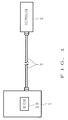
- FIGS. 1 and 2 each schematically show the overall construction of a magnetic bearing device.
- the device comprises a magnetic bearing main body 1, a controller 2 therefor and a cable 3 for interconnecting these components.
- the magnetic bearing main body 1 which is adapted to magnetically levitate a rotary body 5 within a casing 4, comprises an axial magnetic bearing and two radial magnetic bearings for magnetically levitating the rotary body 5, an axial position sensor unit for detecting the axial position of the rotary body 5, two radial position sensor units for detecting the radial position of the rotary body 5, a high-frequency motor for rotating the rotary body 5 at a high speed, and a plurality of protective bearings for limiting the movable range of the rotary body 5.
- these bearings and units one radial magnetic bearing 6 and one radial position sensor unit 7 are shown in FIG. 2.
- the radial magnetic bearing 6 comprises two pairs of electromagnets 8 arranged at opposite sides of the rotary body 5 in two respective radial control axis directions orthogonal to each other as if the magnets 8 in each pair hold the rotary body from opposite sides.
- Each pair of electromagnets 8 attract the rotary body 5 from opposite sides of the radial control axis direction to magnetically levitate the rotary body.
- the axial magnetic bearing comprises a pair of electromagnets arranged at opposite sides of a flange of the rotary body 5 as if holding the flange from opposite sides in an axial control axis direction, whereby the rotary body 5 is attracted from opposite sides in the axial control axis direction for magnetic leviation.
- the radial position sensor unit 7 comprises two pairs of radial position sensors 9 arranged in the vicinity of the magnets 8 at opposite sides of the rotary body 5 in the two respective radial control axis directions as if the sensors 9 in each pair hold the rotary body from opposite side. Based on the difference between the output signals of the position sensors 9 in each pair, the position (displacement) of the rotary body 5 in the radial control axis direction concerned is determined.
- the axial position sensor unit comprises a single axial position sensor disposed as opposed to an end face of suitable portion of the rotary body 5. The position (displacement) of the rotary body in the axial control axis direction is determined based on the output signal of this position sensor.
- a detailed description will not be given of the axial magnetic bearing, radial magnetic bearing 6, axial position sensor unit, radial position sensor unit 7, high-frequency motor and protective bearing since these components are known.
- the main body 1 is provided with memory means having stored therein characteristics of the rotary body 5 and the electromagnets 8, i.e. a ROM 30.
- the ROM 30 is mounted on a suitable portion, for example, of the casing 4. These characteristics include mechanical accuracy such as the error (center position error) of the magnetic center position of the rotary body 5 relative to the mechanical center position thereof, and physical characteristics of the rotary body 5 such as the characteristic frequency and unbalance.
- Stored in connection with the center position error are the values of errors in the axial control axis direction and in the two radical control axis directions orthogonal to each other.
- the characteristic frequency of the rotary body 5 the relationship between the number of revolutions of the rotary body 5 and the bending moment thereof is stored to indicate how the bending moment varies with the number of revolutions.
- the unbalance of the rotary body 5 the relationship between the number of revolutions of the rotary body 5 and the unbalance is stored to show how the mode of unbalance varies with the number of revolutions.
- the pair of electromagnets in each control axis direction are driven, one at a time, to move the rotary body 5 to opposite limit positions in the control axis direction, and the mechanical center position with respect to the control axis direction is determined from the output signals of the position sensors in the same control axis direction at the respective limit positions.
- the limit position of the rotary body 5 is the position where the rotary body 5 is brought to a halt by contact with the protective bearing when only one of the electromagnets in the control axis direction is driven to attract the rotary body 5 in the direction.
- the average of the two limit positions in each control axis direction gives the mechanical center position in the direction.
- the ROM 30 may have stored therein the minimum essential characteristics required of the magnetic bearing device. In addition to the mechanical accuracy and physical characteristics, the production number of the magnetic bearing main body 1, etc. may be stored in the ROM 30.
- the electromagnets 8 and the position sensors 9 are connected by electric wires 10 to corresponding contacts 12 of a connector 11 secured to the casing 4.
- the metal parts of these connections are covered with rubber or like insulator 13.
- the ROM 30, and the unillustrated axial magnetic bearing, radial magnetic bearing, axial position sensor unit, radial position sensor unit and high-frequency motor are also connected by electric wires to the connector or to separate connectors.
- the cable 3 comprises a plurality of electric wires 14 corresponding to the respective wires 10 of the magnetic bearing main body 1 and connected, each at its opposite ends, to corresponding contacts 17, 18 of connectors 15, 16.
- the connector 15 of the cable 3 is connected to the connector 11 of the main body 1, and the other connector 16 thereof to a connector 19 of the controller 2.
- the connector 16 of the cable 3 adjacent the controller 2 has two identification contacts 20 in addition to the contacts 18 for the wires.
- a resistor 21 connected between these contacts 20 provides electrical identification means for discriminating the length of the cable 3.
- the resistance of the resistor 21 is altered with the length of the cable 3. For example, the resistance is 10 k ⁇ , 20 k ⁇ , 30 k ⁇ or 40 k ⁇ when the length of the cable 3 is 5 m, 10 m, 15 m or 20 m, respectively.
- the connector 19 on the controller 2 has two identification contacts 23 corresponding to the identification contacts 20 in addition to wire contacts 22 corresponding to the wire contacts 18 of the connector 16 of the cable 3.
- the controller 2 has a voltage amplifier for amplifying the outputs signals of the position sensors, a power amplifier for driving the electromagnets and a computer for controlling the device in its entirety.
- the controller 2 detects the position of the rotary body 5 with respect to the axial control axis direction and the radial control axis directions from the outputs signals from the axial position sensor unit and the radial position sensor units 7 and controls the axial magnetic bearing and the electromagnets 8 of the radial magnetic bearings 6, whereby the rotary body 5 is magnetically levitated at a predetermined position.
- the controller 2 further controls the high-frequency motor to rotate the motor at a predetermined speed. Such operation of the controller 2 is known and therefore will not be described in detail.
- the controller 2 has stored therein constants for a plurality of sets of control corresponding respectively to different lengths of cables 3. These constants include, for example, the gain and quantity of offset of the voltage amplifier for compensating for the attenuation and offset of the output voltage of the position sensor 9.
- the controller 2 has further stored therein data for setting optimum control parameters for the characteristic frequency and unbalance of the rotary body 5.
- the controller 2 When starting the magnetic bearing device, the controller 2 detects the resistance of the resistor 21 of the cable 3 to discriminate the length of the cable 3, and automatically selects and sets corresponding constants, e.g., a gain and quantity of offset.
- the controller further reads data as to the mechanical accuracy and physical properties of the magnetic bearing main body 1 from the ROM 30, and based on the data, the controller automatically adjusts itself for holding the rotary body 5 at the magnetic center position and automatically sets control parameters in accordance with the characteristic frequency and unbalance of the rotary body 5.
- the controller determines the magnetic center position based on the center position errors read from the ROM 30, and automatically sets a control target position with respect to each control axis direction so that the magnetic center position matches the control target position (neutral position) of the rotary body 5. Also automatically set are optimum control parameters required for the characteristic frequency and unbalance of the rotary 5 read from the ROM 30.
- the magnetic bearing main body 1 is thereafter controlled using the constants, control target positions and control parameters thus set.
- the magnetic bearing device described there may arise a need to alter the length of the cable 3, for example, in the case where the site of installation of the magnetic bearing main body 1 or controller 2 is changed. Further when the controller 2 is connected to the magnetic bearing main body 1 by the cable 3, the presence of the cable 3 results in attenuation (attenuation of amplitude) of the output voltage of the position sensor and offset thereof (offset of voltage value at the center of amplitude), so that these results need to be compensated for on the controller 2.
- the attenuation of the output voltage is compensated for by adjusting the gain of the voltage amplifier of the controller 2, and the offset by offsetting the output voltage in the reverse direction on the controller 2.
- the gain and quantity of offset of the voltage amplifier included in the constants for control.
- the quantity of attenuation and quantity of offset of the position sensor output voltage vary with the length of the cable 3 and increase as the cable length increases. For this reason, it is necessary to set the gain and offset quantity of the voltage amplifier in the controller 3 according to the length of the cable 3, whereas since the length of the cable 3 is conventionally not detectable when it is merely connected, it has been difficult to set these constants. For example, it appears feasible to measure the quantity of attenuation and quantity of offset of the actual output voltage when the cable 3 is connected and to set constants based on the measurements, but the setting procedure is then very cumbersome.
- the resistor 21 provided in the cable 3 enables the controller 2 to automatically discriminate the length of the cable 3 as connected and automatically set control constants in accordance with the length. This obviates the need for the cumbersome constant setting procedure when the cable 3 is replaced by another.
- the interior of the casing 4 of the main body 1 holds a vacuum. If the metal parts of connections between the wires 10 and the connector 11 are left exposed, vacuum discharge is likely to occur between the exposed parts. In the event of vacuum discharge occurring across the wires for the motor, the inverter for driving the motor will be damaged. With the device described, however, the metal parts of the connections are all covered with the insulator 13 and therefore prevented from vacuum discharge, whereby the inverter is protected from damage.
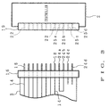
- FIG. 3 shows a modification of electrical identification means for the cable 3.
- a cable connector 16 adjacent to the controller 2 has four identification contacts 24a, 24b, 24c, 24d in addition to the wire contacts 18. These contacts will be designated collectively by the reference numeral 24 and individually termed the first contact 24a, second contact 24b, third contact 24c and fourth contact 24d when there arises a need for distinction. Depending on the length of the cable 3, the first contact 24a is connected to the contact 24b, 24c or 24d or to none of the other contacts for short-circuiting.
- the first contact 24a is connected to the second contact 24b when the cable 3 has a length of 5 m, to the third contact 24c for a length of 10 m, to the fourth contact 24d for a length of 15 m, or to none of the contacts 24b, 24c, 24d for a length of 20 m.
- a connector 19 on the controller 2 has, in addition to the wire contacts 22, four identification contacts 25a, 25b, 25c, 25d corresponding to the respective identification contacts 24 of the cable connector 16.
- the controller 2 detects the resistance between the first contact 24a and the other contact 24b, 24c or 24d to discriminate the short-circuit pattern and thereby detect the length of the cable 3.
- the illustrated arrangement has the same construction as the foregoing embodiment with the exception of the above feature. Throughout the drawings, like parts are designated by like reference numerals.
Landscapes
- Engineering & Computer Science (AREA)
- General Engineering & Computer Science (AREA)
- Mechanical Engineering (AREA)
- Physics & Mathematics (AREA)
- Electromagnetism (AREA)
- Magnetic Bearings And Hydrostatic Bearings (AREA)
Priority Applications (3)
| Application Number | Priority Date | Filing Date | Title |
|---|---|---|---|
| US08/843,280 US6348749B1 (en) | 1997-04-14 | 1997-04-14 | Magnetic bearing device and method of starting the device |
| EP97106167A EP0872655B1 (fr) | 1997-04-14 | 1997-04-15 | Dispositif de palier magnétique et procédé de démarrage du dispositif |
| DE69732959T DE69732959T2 (de) | 1997-04-15 | 1997-04-15 | Magnetische Lagervorrichtung und Verfahren zum Starten der Vorrichtung |
Applications Claiming Priority (2)
| Application Number | Priority Date | Filing Date | Title |
|---|---|---|---|
| US08/843,280 US6348749B1 (en) | 1997-04-14 | 1997-04-14 | Magnetic bearing device and method of starting the device |
| EP97106167A EP0872655B1 (fr) | 1997-04-14 | 1997-04-15 | Dispositif de palier magnétique et procédé de démarrage du dispositif |
Publications (2)
| Publication Number | Publication Date |
|---|---|
| EP0872655A1 true EP0872655A1 (fr) | 1998-10-21 |
| EP0872655B1 EP0872655B1 (fr) | 2005-04-06 |
Family
ID=26145383
Family Applications (1)
| Application Number | Title | Priority Date | Filing Date |
|---|---|---|---|
| EP97106167A Expired - Lifetime EP0872655B1 (fr) | 1997-04-14 | 1997-04-15 | Dispositif de palier magnétique et procédé de démarrage du dispositif |
Country Status (2)
| Country | Link |
|---|---|
| US (1) | US6348749B1 (fr) |
| EP (1) | EP0872655B1 (fr) |
Cited By (2)
| Publication number | Priority date | Publication date | Assignee | Title |
|---|---|---|---|---|
| EP1036951A4 (fr) * | 1997-12-02 | 2005-03-30 | Ebara Corp | Organe de commande a palier magnetique et dispositif a pompe turbomoleculaire |
| EP2781774B1 (fr) | 2013-03-22 | 2020-07-15 | Rieter CZ s.r.o. | Procédé pour corriger des variations de paramètres de composants et/ou d'assemblage de palier magnétique actif et palier magnétique actif portant des moyens de travail rotatif |
Families Citing this family (8)
| Publication number | Priority date | Publication date | Assignee | Title |
|---|---|---|---|---|
| JP3130890B2 (ja) * | 1999-02-25 | 2001-01-31 | セイコー精機株式会社 | 磁気軸受装置及び磁気軸受制御装置 |
| US6600727B1 (en) * | 1999-05-27 | 2003-07-29 | Cisco Technology, Inc. | Distributed network repeater system |
| US6462435B1 (en) * | 1999-06-11 | 2002-10-08 | Cisco Technology, Inc. | Cable detect and EMI reduction apparatus and method |
| JP2006344503A (ja) * | 2005-06-09 | 2006-12-21 | Boc Edwards Kk | 端子構造及び真空ポンプ |
| US8055096B2 (en) * | 2006-05-10 | 2011-11-08 | Research In Motion Limited | Method and system for incremental patching of binary files |
| JP6086001B2 (ja) * | 2013-03-13 | 2017-03-01 | 株式会社島津製作所 | 真空ポンプ |
| EP3511585B1 (fr) * | 2018-01-15 | 2020-07-08 | Siemens Aktiengesellschaft | Procédé de surveillance d'un dispositif de palier magnétique |
| JP7214805B1 (ja) * | 2021-08-30 | 2023-01-30 | エドワーズ株式会社 | 磁気軸受装置及び真空ポンプ |
Citations (1)
| Publication number | Priority date | Publication date | Assignee | Title |
|---|---|---|---|---|
| EP0156730A1 (fr) * | 1984-03-26 | 1985-10-02 | SOCIETE EUROPEENNE DE PROPULSION (S.E.P.) Société Anonyme dite: | Dispositif de compensation des défauts géométriques d'un anneau de détecteur radial de suspension magnétique active de rotor |
Family Cites Families (12)
| Publication number | Priority date | Publication date | Assignee | Title |
|---|---|---|---|---|
| JPS56140411A (en) * | 1980-04-04 | 1981-11-02 | Fanuc Ltd | Numerical control system of machine tool |
| DE3120691A1 (de) * | 1981-05-23 | 1982-12-16 | Teldix Gmbh, 6900 Heidelberg | Magnetlager |
| US4540262A (en) * | 1982-03-05 | 1985-09-10 | Minolta Camera | Camera accessory with data producer |
| US4884329A (en) * | 1987-02-20 | 1989-12-05 | Research Development Corporation | Precision automatic assembly apparatus, with electromagnetically supported member and assembly method using same |
| JP2516382B2 (ja) * | 1987-11-06 | 1996-07-24 | セイコー精機株式会社 | 磁気軸受を主軸にもつ加工装置 |
| JPH01195994A (ja) * | 1988-01-31 | 1989-08-07 | Shimadzu Corp | 磁気軸受ターボ分子ポンプの制御装置 |
| JP2852747B2 (ja) * | 1988-03-18 | 1999-02-03 | セイコー精機株式会社 | 内面研削盤 |
| US5347190A (en) * | 1988-09-09 | 1994-09-13 | University Of Virginia Patent Foundation | Magnetic bearing systems |
| JPH0720359B2 (ja) * | 1990-03-16 | 1995-03-06 | 株式会社荏原製作所 | 回転体のアンバランス修正装置 |
| US5486729A (en) * | 1992-03-09 | 1996-01-23 | Hitachi, Ltd. | Method and apparatus for controlling a magnetic bearing |
| JP3319030B2 (ja) * | 1993-05-18 | 2002-08-26 | 株式会社日立製作所 | 磁気軸受の制御装置およびそれを用いた回転機械 |
| US5627421A (en) * | 1994-10-28 | 1997-05-06 | Barber-Colman Company | High efficiency drive circuit for an active magnetic bearing system |
-
1997
- 1997-04-14 US US08/843,280 patent/US6348749B1/en not_active Expired - Fee Related
- 1997-04-15 EP EP97106167A patent/EP0872655B1/fr not_active Expired - Lifetime
Patent Citations (1)
| Publication number | Priority date | Publication date | Assignee | Title |
|---|---|---|---|---|
| EP0156730A1 (fr) * | 1984-03-26 | 1985-10-02 | SOCIETE EUROPEENNE DE PROPULSION (S.E.P.) Société Anonyme dite: | Dispositif de compensation des défauts géométriques d'un anneau de détecteur radial de suspension magnétique active de rotor |
Cited By (3)
| Publication number | Priority date | Publication date | Assignee | Title |
|---|---|---|---|---|
| EP1036951A4 (fr) * | 1997-12-02 | 2005-03-30 | Ebara Corp | Organe de commande a palier magnetique et dispositif a pompe turbomoleculaire |
| EP2781774B1 (fr) | 2013-03-22 | 2020-07-15 | Rieter CZ s.r.o. | Procédé pour corriger des variations de paramètres de composants et/ou d'assemblage de palier magnétique actif et palier magnétique actif portant des moyens de travail rotatif |
| EP2781774B2 (fr) † | 2013-03-22 | 2023-06-21 | Rieter CZ s.r.o. | Procédé pour corriger des variations de paramètres de composants et/ou d'assemblage de palier magnétique actif et palier magnétique actif portant des moyens de travail rotatif |
Also Published As
| Publication number | Publication date |
|---|---|
| EP0872655B1 (fr) | 2005-04-06 |
| US6348749B1 (en) | 2002-02-19 |
Similar Documents
| Publication | Publication Date | Title |
|---|---|---|
| EP0872655B1 (fr) | Dispositif de palier magnétique et procédé de démarrage du dispositif | |
| US6215218B1 (en) | Control magnetic bearing | |
| KR101074319B1 (ko) | 자기 베어링 장치 및 진공 펌프 | |
| JP2700904B2 (ja) | 磁気浮上体の制御装置 | |
| JP4852609B2 (ja) | 磁気ベアリング装置用のロータ軸 | |
| JP4578045B2 (ja) | 電気機械のロータの位置を決定する方法および位置センサ | |
| US20090009017A1 (en) | Bearing apparatus and centrifugal compressor provided with same | |
| JP4652448B2 (ja) | 軸の偏心を検出するための装置 | |
| CN110160429A (zh) | 无轴承的角度测量装置 | |
| EP1036951B1 (fr) | Palier magnetique et dispositif a pompe turbomoleculaire | |
| CN116772699B (zh) | 磁悬浮电机特性的标定方法及装置 | |
| JP3622037B2 (ja) | 磁気軸受装置およびその起動方法 | |
| EP1978269A2 (fr) | Palier magnétique et broche à palier magnétique | |
| CN115566967A (zh) | 无轴承磁悬浮电机开机自检装置及方法 | |
| JPH09189326A (ja) | 磁気軸受装置 | |
| KR100433070B1 (ko) | 자기베어링장치및그기동방법 | |
| EP1318310B1 (fr) | Organe de commande à palier magnétique | |
| US20010050940A1 (en) | Electric discharge gas laser | |
| JP2002333020A (ja) | 磁気軸受制御装置 | |
| JP3458905B2 (ja) | 磁気軸受装置 | |
| JPH0231020A (ja) | 磁気軸受装置 | |
| KR100837359B1 (ko) | 회전체 진동 측정용 인덕티브센서의 제어 장치 및 방법 | |
| JP3625904B2 (ja) | 磁気軸受装置 | |
| JP3036101B2 (ja) | 磁気軸受 | |
| JP3451829B2 (ja) | 加速度センサ |
Legal Events
| Date | Code | Title | Description |
|---|---|---|---|
| PUAI | Public reference made under article 153(3) epc to a published international application that has entered the european phase |
Free format text: ORIGINAL CODE: 0009012 |
|
| AK | Designated contracting states |
Kind code of ref document: A1 Designated state(s): CH DE FR GB LI |
|
| AX | Request for extension of the european patent |
Free format text: AL;LT;LV;RO;SI |
|
| 17P | Request for examination filed |
Effective date: 19990107 |
|
| AKX | Designation fees paid |
Free format text: CH DE FR GB LI |
|
| 17Q | First examination report despatched |
Effective date: 19991220 |
|
| GRAP | Despatch of communication of intention to grant a patent |
Free format text: ORIGINAL CODE: EPIDOSNIGR1 |
|
| RAP1 | Party data changed (applicant data changed or rights of an application transferred) |
Owner name: KOYO SEIKO CO., LTD. |
|
| GRAS | Grant fee paid |
Free format text: ORIGINAL CODE: EPIDOSNIGR3 |
|
| GRAA | (expected) grant |
Free format text: ORIGINAL CODE: 0009210 |
|
| AK | Designated contracting states |
Kind code of ref document: B1 Designated state(s): CH DE FR GB LI |
|
| REG | Reference to a national code |
Ref country code: GB Ref legal event code: FG4D |
|
| REG | Reference to a national code |
Ref country code: CH Ref legal event code: EP |
|
| REG | Reference to a national code |
Ref country code: CH Ref legal event code: NV Representative=s name: PATENTANWALTSBUERO JEAN HUNZIKER |
|
| REF | Corresponds to: |
Ref document number: 69732959 Country of ref document: DE Date of ref document: 20050512 Kind code of ref document: P |
|
| PLBE | No opposition filed within time limit |
Free format text: ORIGINAL CODE: 0009261 |
|
| STAA | Information on the status of an ep patent application or granted ep patent |
Free format text: STATUS: NO OPPOSITION FILED WITHIN TIME LIMIT |
|
| ET | Fr: translation filed | ||
| 26N | No opposition filed |
Effective date: 20060110 |
|
| PGFP | Annual fee paid to national office [announced via postgrant information from national office to epo] |
Ref country code: CH Payment date: 20080415 Year of fee payment: 12 |
|
| PGFP | Annual fee paid to national office [announced via postgrant information from national office to epo] |
Ref country code: GB Payment date: 20080416 Year of fee payment: 12 |
|
| REG | Reference to a national code |
Ref country code: CH Ref legal event code: PL |
|
| GBPC | Gb: european patent ceased through non-payment of renewal fee |
Effective date: 20090415 |
|
| PG25 | Lapsed in a contracting state [announced via postgrant information from national office to epo] |
Ref country code: LI Free format text: LAPSE BECAUSE OF NON-PAYMENT OF DUE FEES Effective date: 20090430 Ref country code: CH Free format text: LAPSE BECAUSE OF NON-PAYMENT OF DUE FEES Effective date: 20090430 |
|
| PG25 | Lapsed in a contracting state [announced via postgrant information from national office to epo] |
Ref country code: GB Free format text: LAPSE BECAUSE OF NON-PAYMENT OF DUE FEES Effective date: 20090415 |
|
| REG | Reference to a national code |
Ref country code: FR Ref legal event code: PLFP Year of fee payment: 20 |
|
| PGFP | Annual fee paid to national office [announced via postgrant information from national office to epo] |
Ref country code: FR Payment date: 20160309 Year of fee payment: 20 |
|
| PGFP | Annual fee paid to national office [announced via postgrant information from national office to epo] |
Ref country code: DE Payment date: 20160412 Year of fee payment: 20 |
|
| REG | Reference to a national code |
Ref country code: DE Ref legal event code: R071 Ref document number: 69732959 Country of ref document: DE |