EP0872680A2 - Vorrichtung zur Inspektion und Instandhaltung von Rohren - Google Patents
Vorrichtung zur Inspektion und Instandhaltung von Rohren Download PDFInfo
- Publication number
- EP0872680A2 EP0872680A2 EP98250042A EP98250042A EP0872680A2 EP 0872680 A2 EP0872680 A2 EP 0872680A2 EP 98250042 A EP98250042 A EP 98250042A EP 98250042 A EP98250042 A EP 98250042A EP 0872680 A2 EP0872680 A2 EP 0872680A2
- Authority
- EP
- European Patent Office
- Prior art keywords
- chamber
- pipe
- tube
- elements
- pressure chamber
- Prior art date
- Legal status (The legal status is an assumption and is not a legal conclusion. Google has not performed a legal analysis and makes no representation as to the accuracy of the status listed.)
- Granted
Links
Images


Classifications
-
- G—PHYSICS
- G01—MEASURING; TESTING
- G01M—TESTING STATIC OR DYNAMIC BALANCE OF MACHINES OR STRUCTURES; TESTING OF STRUCTURES OR APPARATUS, NOT OTHERWISE PROVIDED FOR
- G01M3/00—Investigating fluid-tightness of structures
- G01M3/02—Investigating fluid-tightness of structures by using fluid or vacuum
- G01M3/022—Test plugs for closing off the end of a pipe
-
- E—FIXED CONSTRUCTIONS
- E03—WATER SUPPLY; SEWERAGE
- E03F—SEWERS; CESSPOOLS
- E03F7/00—Other installations or implements for operating sewer systems, e.g. for preventing or indicating stoppage; Emptying cesspools
- E03F7/12—Installations enabling inspection personnel to drive along sewer canals
-
- E—FIXED CONSTRUCTIONS
- E03—WATER SUPPLY; SEWERAGE
- E03F—SEWERS; CESSPOOLS
- E03F9/00—Arrangements or fixed installations methods or devices for cleaning or clearing sewer pipes, e.g. by flushing
-
- F—MECHANICAL ENGINEERING; LIGHTING; HEATING; WEAPONS; BLASTING
- F16—ENGINEERING ELEMENTS AND UNITS; GENERAL MEASURES FOR PRODUCING AND MAINTAINING EFFECTIVE FUNCTIONING OF MACHINES OR INSTALLATIONS; THERMAL INSULATION IN GENERAL
- F16L—PIPES; JOINTS OR FITTINGS FOR PIPES; SUPPORTS FOR PIPES, CABLES OR PROTECTIVE TUBING; MEANS FOR THERMAL INSULATION IN GENERAL
- F16L55/00—Devices or appurtenances for use in, or in connection with, pipes or pipe systems
- F16L55/26—Pigs or moles, i.e. devices movable in a pipe or conduit with or without self-contained propulsion means
-
- G—PHYSICS
- G01—MEASURING; TESTING
- G01M—TESTING STATIC OR DYNAMIC BALANCE OF MACHINES OR STRUCTURES; TESTING OF STRUCTURES OR APPARATUS, NOT OTHERWISE PROVIDED FOR
- G01M3/00—Investigating fluid-tightness of structures
- G01M3/02—Investigating fluid-tightness of structures by using fluid or vacuum
- G01M3/26—Investigating fluid-tightness of structures by using fluid or vacuum by measuring rate of loss or gain of fluid, e.g. by pressure-responsive devices, by flow detectors
- G01M3/28—Investigating fluid-tightness of structures by using fluid or vacuum by measuring rate of loss or gain of fluid, e.g. by pressure-responsive devices, by flow detectors for pipes, cables or tubes; for pipe joints or seals; for valves ; for welds
- G01M3/2807—Investigating fluid-tightness of structures by using fluid or vacuum by measuring rate of loss or gain of fluid, e.g. by pressure-responsive devices, by flow detectors for pipes, cables or tubes; for pipe joints or seals; for valves ; for welds for pipes
- G01M3/2823—Investigating fluid-tightness of structures by using fluid or vacuum by measuring rate of loss or gain of fluid, e.g. by pressure-responsive devices, by flow detectors for pipes, cables or tubes; for pipe joints or seals; for valves ; for welds for pipes using pigs or moles traveling in the pipe
-
- F—MECHANICAL ENGINEERING; LIGHTING; HEATING; WEAPONS; BLASTING
- F16—ENGINEERING ELEMENTS AND UNITS; GENERAL MEASURES FOR PRODUCING AND MAINTAINING EFFECTIVE FUNCTIONING OF MACHINES OR INSTALLATIONS; THERMAL INSULATION IN GENERAL
- F16L—PIPES; JOINTS OR FITTINGS FOR PIPES; SUPPORTS FOR PIPES, CABLES OR PROTECTIVE TUBING; MEANS FOR THERMAL INSULATION IN GENERAL
- F16L2101/00—Uses or applications of pigs or moles
- F16L2101/30—Inspecting, measuring or testing
Definitions
- the invention relates to a device for Inspection and maintenance of pipes according to the Preamble of claim 1.
- Such devices are used, for example, around the sewage system, i.e. Attachments to the collection and drainage of water, for perfect function and to check that it is free of defects and by appropriate Maintenance or renovation measures in operational order and keep it in a safe operating condition.
- EP 0 377 141 A2 describes a pipe testing and shut-off device known, which has a fixed tubular cylindrical Inner part for the passage of the Pipe directed medium and two in the axial direction spaced annular Pressure chambers, the outer surfaces of which are under pressure on the inner wall of the pipe.
- the pressure chambers are designed to be elastic, that they are at further pressurization expand in the axial direction and the chamber between decrease in size so that the pressure in it increases becomes. Accordingly, this device is primarily used for testing of pipe leaks, especially with socket connections with the help of the generated in the chamber Pressure used.
- DE 43 15 927 A1 describes a method for sealing and repairing damaged buried underground Pipelines known that both when interrupted the through the pipeline Fluid flow as well as persistent Liquid flow can be carried out.
- the point to be sealed by the closure body be completed and in the locked room the components of a curing mixture are introduced.
- the object of the present invention is a device for inspection and maintenance of pipes such as sewers and sewers to make available, with their help too with further drainage of waste water through the pipe one Inspection and maintenance or renovation of the whole Rohres is possible. It is also a task of the present invention, an apparatus is available to represent those in the prior art avoids disadvantages and a simple and safe inspection and maintenance of sewage pipes enables.
- Chamber is fixed inside the pipe bounded space is available that is free of waste water and within it an inspection or processing the pipe wall is possible. Because the Chamber according to the invention not over the entire cross section of the pipe and consequently the water drain not completely blocked within the tube, it is possible to work on the pipe wall to carry out without the operation of the sewage pipe interrupt.
- the chamber can, for example, with the help are freed of compressed air from waste water and in Flooded after completion of the work are transported to another point on the canal or removed. This can be done by a conventional Compressed air supply via compressed air lines and controlled valves for both air supply and for flooding with water.
- the bracing elements a certain Clamping the room, there is any risk of damage or injury for devices or workers in the chamber locked out. If the chamber is designed as a pressure chamber is, can, too, at work by people in the pressure chamber any danger from possible disruptions to pressure chamber operation Exclude sewage, workers inside the pressure chamber equipped with diving equipment will.
- a particularly stable and secure seal of the Sealing elements against the wall of the tube achieved by inflatable closure elements, for example through elastic pressure hoses such as rubber beads, Tires and the like. You serve not just the waterproofing, but can at the same time better tensioning and locking of the device compared to the runoff and depending on the runoff possibly also accumulate wastewater.
- the closure elements can be in circumferential Flanges, for example with the bulkheads are welded, stored and can with the help conventional compressed air or hydraulic fluid lines inflated with air or liquid or her Pressure can be controlled by suitable, controlled valves be relaxed in a conventional manner.
- the pressure chamber can have a relief opening, for example, have a valve for the Outflow of waste water when compressed air is applied the pressure chamber.
- a security gate for the entry and exit of workers be attached to the pressure chamber.
- help robots or monitoring devices such as remote controlled cameras inside the pressure chamber and there within by the bracing elements spanned space are arranged, the necessary inspection and repair work perform.
- the chamber can be moved using such as cables or walking devices, be moved in the longitudinal direction of the tube or with the help of rotating devices around the axis of the tube are rotated so that all successively Areas of the pipe wall within the pressure chamber come to rest and without disability Wastewater can be examined or repaired. It is only important to ensure that at the displacement or rotation of the pressure chamber successively into these wall areas overlap sufficiently to cover the entire wall to be able to edit seamlessly.
- the chamber can have a circular, egg or mouth cross section or any of these and other forms have combined cross-sectional shapes. So can the chamber by suitable selection of the cross-sectional shape be shaped so that with drain cross sections Wastewater channels for dry weather drainage remains open.
- bracing elements ring-shaped along the tube wall over the entire Extend the inner circumference of the tube.
- Bracing elements can be attached to two bulkhead walls that are across the pipe direction extend part of the pipe cross-section.
- These bulkhead walls can by a longitudinal bulkhead, the extends along the tube, be completed, so that the pipe runs along its direction through the Longitudinal bulkhead is divided into two parts, one Part that is completed by the transverse and longitudinal bulkheads is, forms a pressure chamber.
- Another advantageous embodiment has transverse bulkhead walls on that ring-shaped on the bracing elements are attached and have a central opening.
- the openings of the two bulkhead walls are connected by a tubular longitudinal bulkhead, so that an annular pressure chamber forms, the central opening forms a passage for the waste water.
- This passage is the final cross section available to secure the drainage, so that the pipe not for the period of maintenance work must be completely shut down.
- a sewage pump be used to increase the drain.
- the bracing and / or sealing elements Openings for the passage of control cables, Supply lines or the like in the pressure chamber exhibit.
- the pressure chamber can also be used to locate leaks, for inspection and also for checking carried out Repair and refurbishment work for leak testing the channel wall can be used.
- To the pressure chamber is filled with a fluid pressure medium and the one that occurs due to leaks etc. Pressure loss, loss of medium or the outside Medium amount observed. Suitable as a print medium especially gases and liquids.
- the chamber is at its in the direction of flow of the medium the front end is only partially closed, i.e. it is not designed as a pressure chamber and stands under the natural atmosphere in the pipe. By the chamber is then appropriately compared to this sealed, with the pipe inside in front and behind the Chamber connected channel led.
- the channel can be adapted to the respective working conditions in the cross-sectional area of the chamber its position can be changed. For this he can be advantageous at the front and back of the chamber be rotatably mounted and eccentric within the chamber to the axis between its pivot points.
- the sealing elements on the rear in the direction of flow of the medium At the end of the chamber an opening or opening flap to be closed should be provided. That’s it for example possible to shut up in an emergency to open to a higher drain of the sewage to reach.
- the chamber must be staffed or any remote-controlled robots be.
- Fig. 1 the in a sewage pipe 4 with a Pipe wall 1 arranged device bracing elements 5 and sealing elements that span a chamber 2.
- the bracing and sealing elements are like this arranged that the chamber 2 is annular along the wall 1 of the tube 4 extends.
- the bracing elements 5 extend annularly along the Pipe wall 1 and web-like radially inwards for receiving of the sealing elements.
- the sealing elements exist from side bulkheads 13 and an inner tube (Longitudinal bulkhead wall) 8, which is designed as an inner tube is.
- the side bulkheads 13 are over closure elements 6 sealing with the wall 1 of the sewage pipe 4 positively connected so that the chamber 2 is designed as a pressure chamber.
- the closure elements 6 consist of an annular wall 1 Rubber beads and are in with the bracing and Sealing elements welded along the pipe wall 1 circumferential flanges. Can be used for sealing with a fluid medium such as water or inflated air. Not shown are for the inflation with medium and for that Draining the medium necessary pressure lines, controls and valves.
- the inner tube 8 spans a discharge cross section 3 through which also during the Operation of the pressure chamber, at least partially drain off.
- a pump at the entrance of this be provided so that the amount of wastewater passed through can be increased.
- the pump can run simultaneously serve to generate a water jet with which cleaned the tube wall 1 and the device can be.
- At one end of the device is a Cable 10 attached with which the pressure chamber in Longitudinal direction of the tube 4 can be moved.
- the closure elements 6 After positioning the pressure chamber 2 in the sewage pipe 4, the closure elements 6 with a printing medium, for example water or air and pressed against the inner wall 1 of the tube 4. Subsequently the pressure chamber 2 is so long over here conventional pressure lines, also not shown, Control devices and valves with compressed air pressurized until all of the wastewater from the pressure chamber 2 is removed. As a relief opening can in One of the bulkheads is provided with a controllable valve be opposite the outside water pressure closes. This is the inner wall 1 of the sewage pipe 4 in the area of the pressure chamber 2 anhydrous and for all maintenance measures, such as cleaning, Inspection and repair, accessible.
- a printing medium for example water or air
- Pressure chamber 2 is one or are not shown here several robots with TV equipment, all of which Can perform operations, flexibly installed, so that they expose all exposed areas of the sewer 4 can achieve.
- this technical Devices on the inner tube 8 longitudinally and / or radially movable be performed.
- the new position should the old overlap a little to ensure a seamless editing to be able to make the pipe wall 1.
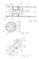
- FIG. 1b shows a cross section through the device according to Fig. La along the line drawn there A-A.
- FIG. 1b clearly shows the inner tube 8, with the help of the tensioning elements 5 a pressure chamber 2 spans.
- the pressure chamber 2 is ring-shaped against the tube wall 1 with the help of annular closure elements 6 sealed.
- Fig. 1c shows the device shown in Fig. La in perspective view, here clearly the tubular drain cross section 3, through the inner tube 8 is formed, can be seen.
- Fig. 2 shows a device as in Fig. La, wherein but instead of a cable, a walking device 11 arranged to move the device thereon is.
- the walking device 11 also has closure elements 6 with which the walking device 11 is fixed to the pipe wall.
- the Walking device 11 via a telescopic device 12, for example hydraulic cylinders, with the device connected.
- FIG. 3a shows a device that also braces and has sealing elements that a pressure chamber 2 span within a sewer 4.
- the pressure chamber 2 has a swivel joint 14 which is in the central axis the device and the sewage pipe 4 arranged is.
- a walking device 11 with a telescopic cylinder 12 arranged At this pivot 14 is still a walking device 11 with a telescopic cylinder 12 arranged, the function of which has already been described in FIG. 2 has been.
- a rotary movement of the device the central axis of the tube 4 using the swivel 14 possible.
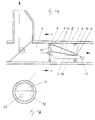
- FIG. 3b shows the device according to FIG. 3a in one Cross section along the line drawn there A-A.
- the pressure chamber 2 through the wall 1 of the tube 4, through two Side bulkheads 13 and a longitudinal bulkhead 7, which are anchored to the bracing elements 5, spanned.
- This longitudinal bulkhead 7 extends along the pipe direction and thereby divides the pipe 4th in two halves.
- Half is the wastewater-free Pressure chamber 2 while in the other half the waste water during the operation of the pressure chamber can continue to drain.
- the longitudinal bulkhead 7 will through the closure elements 9 against the wall 1 of the Tube 4 sealed.
- Rotary joint 14 can be seen about the axis of the device can be rotated. This makes it possible successively all on the inner circumference of the tube To cover 4 lying areas with the pressure chamber 2, so that by appropriate rotation and longitudinal displacement the entire pipe wall 1 can be.
- Fig. 3c shows a perspective view of the in Fig. 3a reproduced device.
- the side bulkhead walls 13 semicircular limit the pressure chamber 2 laterally and over the longitudinal bulkhead 7 are interconnected.
- the closure element 6 that of two are ring-shaped along the inner wall of the sewage pipe 4 extending ring elements and the closure element connected to them 9 exists.
- the swivel 14 In the central axis of the device, which coincides with the central axis of the sewage pipe 4, is the swivel 14, with the the device can be rotated about its central axis can.
- FIG 4a shows a device in which the chamber 2 not designed as a pressure chamber, but on in Flow direction of the medium open front end is so that it communicates with the tube atmosphere stands.
- the medium flows as indicated by the arrow from left to right through pipe 4.
- the seal 13 on the front in the flow direction Accordingly, the end is not closed, but in the upper one Provide part with an opening 16. You must be in be designed in such a way that through the drain cross-section 3 waste water conducted past the chamber 2 cannot flow back into them.
- the discharge cross section 3 is formed by a channel 18, at both ends of the device through the Seal 13 passes and into the tube 4 outside the chamber 2 opens.
- Channel 18 is on the in Direction of flow at the front end with an outlet 17 Mistake.
- the channel 18 can also be configured in this way be that immediately behind his Passing through the seals 13 at each end the device within the chamber 2 by 90 ° is turned (arch), then parallel again to be led to the pipe wall 1 through the chamber 2.
- the channel 18 is pivotable in the Seals 13 stored. This ensures that the channel 18 within the chamber 2 in its Location can also be changed in the middle. He always will pivoted so that he can do the work on least disturbs. To this end, it can be advantageous when the axis of rotation of the channel 18 and the central axis the chamber 2 collapse.
- the seal 13 on the rear in the flow direction End of the device contains a flap 15 which in the Is normally closed.
- the flap 15 are opened so that waste water through the Chamber 2 flows. The prerequisite for this is that the Chamber of personnel and any damage suffered Tool is cleared.
- Struts 19 are between the bracing and sealing elements arranged at both ends of the device, in order to achieve a higher stability especially for the Transport between the individual working positions to lend.
- the device according to FIG. 4 is less complex, easier to use and safer to operate than the devices using a pressure chamber according to FIGS. 1 to 3.
Landscapes
- Engineering & Computer Science (AREA)
- Physics & Mathematics (AREA)
- Life Sciences & Earth Sciences (AREA)
- Hydrology & Water Resources (AREA)
- Public Health (AREA)
- Water Supply & Treatment (AREA)
- Health & Medical Sciences (AREA)
- General Physics & Mathematics (AREA)
- General Engineering & Computer Science (AREA)
- Chemical & Material Sciences (AREA)
- Mechanical Engineering (AREA)
- Combustion & Propulsion (AREA)
- Sewage (AREA)
- Pipe Accessories (AREA)
Abstract
Description
- Fig. 1a
- eine erste Ausführungsform der erfindungsgemäßen Vorrichtung im Längsschnitt,
- Fig. 1b
- die Vorrichtung nach Fig. la im Querschnitt,
- Fig. 1c
- die Vorrichtung nach Fig. la in perspektivischer Darstellung,
- Fig. 2
- eine zweite Ausführungsform der erfindungsgemäßen Vorrichtung im Längsschnitt,
- Fig. 3a
- eine dritte Ausführungsform der erfindungsgemäßen Vorrichtung im Längsschnitt,
- Fig. 3b
- die Vorrichtung nach Fig. 3a im Querschnitt,
- Fig. 3c
- die Vorrichtung nach Fig. 3a in perspektivischer Darstellung,
- Fig. 4a
- eine vierte Ausführungsform der erfindungsgemäßen Vorrichtung im Längsschnitt, und
- Fig. 4b
- die Vorrichtung nach Fig. 4a im Querschnitt entlang der Linie A-A.
Claims (19)
- Vorrichtung zur Inspektion und Instandhaltung von fließfähige Medien leitenden Rohren (4) wie Abwasserkanälen und -leitungen, mit mindestens zwei in Längsrichtung eines Rohres (4) hintereinanderliegenden Verspannelementen (5) vorgesehen sind, die zwischen sich eine Kammer (2) innerhalb eines Rohres (4) aufspannen, dadurch gekennzeichnet, daß die Kammer (2) sich nur über einen Teil des Querschnitts des Rohres (4) erstreckt zumindest am in Fließrichtung des Mediums hinteren Ende der Kammer (2) an den Verspannelementen (5) Abdichtelemente (13), die seitlich dicht mit der Wand (1) des Rohres (4) abschließen, befestigt sind, und daß sich ein Abdichtelement (8) zwischen den Verspannelementen (5) erstreckt, welches die Kammer (2) gegenüber dem Rohrinneren abdichtet.
- Vorrichtung nach Anspruch 1, dadurch gekennzeichnet, daß die Abdichtelemente (8, 13) an den Verspannelementen (5) befestigt sind zur Bildung einer Druckkammer.
- Vorrichtung nach Anspruch 1, dadurch gekennzeichnet, daß die Kammer (2) an ihrem in Fließrichtung des Mediums vorderen Ende nur teilweise geschlossen ist.
- Vorrichtung nach einem der Ansprüche 1 bis 3, dadurch gekennzeichnet, daß zwischen den Abdichtelementen (8, 13) und der Rohrwandung (1) aufblasbare Verschlußelemente (6) angeordnet sind.
- Vorrichtung nach mindestens einem der vorhergehenden Ansprüche, dadurch gekennzeichnet, daß mindestens zwei Verschlußelemente (6) sich ringförmig über den gesamten Innenumfang des Rohres (4) erstrecken.
- Vorrichtung nach Anspruch 2, dadurch gekennzeichnet, daß als Abdichtelemente zwei Querschottwände (13) sich quer zur Rohrlängsrichtung über einen Teil des Rohrquerschnitts erstrecken und eine Längsschottwand (8) sich zwischen den beiden Querschottwänden längs des Rohres erstreckt und den von den Querschottwänden (13) und der Rohrwand (1) umschlossenen Raum abdichtet.
- Vorrichtung nach Anspruch 6, dadurch gekennzeichnet, daß die Querschottwände (13) kreissegmentförmig und die Längsschottwand (7) planar oder entsprechend abgewinkelt ausgebildet sind.
- Vorrichtung nach Anspruch 6, dadurch gekennzeichnet, daß die Querschottwände (13) ringförmig mit einer zentralen Öffnung und die Längsschottwand (8) rohrförmig ausgebildet ist, wobei die Längsschottwand (8) die zentralen Öffnungen der Querschottwände (13) einen Durchlaß durch die Druckkammer (2) bildend verbindet.
- Vorrichtung nach mindestens einem der Ansprüche 2 oder 4 bis 8, dadurch gekennzeichnet, daß die Druckkammer (2) eine Entlastungsöffnung, beispielsweise ein Ventil, aufweist.
- Vorrichtung nach mindestens einem der Ansprüche 2 oder 4 bis 9, dadurch gekennzeichnet, daß die Druckkammer (2) eine Personenschleuse aufweist.
- Vorrichtung nach Anspruch 3, dadurch gekennzeichnet, daß in Längsrichtung des Rohres (4) durch die Kammer (2) ein gegenüber dieser abgedichteter, mit dem Rohrinnern vor und hinter der Kammer (2) verbundener Kanal (18) geführt ist.
- Vorrichtung nach Anspruch 11, dadurch gekennzeichnet, daß der Kanal (18) in der Querschnittsfläche der Kammer (2) in seiner Lage veränderbar ist.
- Vorrichtung nach Anspruch 12, dadurch gekennzeichnet, daß der Kanal (18) am vorderen und hinteren Ende der Kammer (2) drehbar gelagert und innerhalb der Kammer (2) exzentrisch zu der Achse zwischen seinen Drehpunkten verläuft.
- Vorrichtung nach einem der Ansprüche 11 bis 13, dadurch gekennzeichnet, daß in den Abdichtelementen (13) am in Fließrichtung des Mediums hinteren Ende der Kammer (2) eine nach Bedarf zu öffnende oder zu schließende Klappe (15) vorgesehen ist.
- Vorrichtung nach mindestens einem der vorhergehenden Ansprüche, dadurch gekennzeichnet, daß an einem Ende der Kammer (2) eine Seilzugvorrichtung (10) und/oder eine Schreitvorrichtung (11) zur Bewegung der Kammer (2) in Längsrichtung des Rohres (4) angreift.
- Vorrichtung nach mindestens einem der vorhergehenden Ansprüche, dadurch gekennzeichnet, daß eine Vorrichtung (14) zum Drehen der Kammer (2) um die Rohrachse vorgesehen ist.
- Vorrichtung nach mindestens einem der vorhergehenden Ansprüche, dadurch gekennzeichnet, daß die Verspann-(5) und/oder Abdichtelemente (8,13) Öffnungen zur Durchführung von Steuerkabeln oder Versorgungsleitungen in die Kammer (2) aufweisen.
- Vorrichtung nach mindestens einem der vorhergehenden Ansprüche, dadurch gekennzeichnet, daß in der Kammer (2) fernsteuerbare Werkzeuge oder Überwachungsvorrichtungen zur Instandhaltung, Reinigung, Inspektion oder Sanierung des Rohres angeordnet sind.
- Vorrichtung nach mindestens einem der vorhergehenden Ansprüche, dadurch gekennzeichnet, daß am in Fließrichtung des Mediums hinteren Ende der Kammer (2) außerhalb von dieser eine Pumpe angeordnet ist für den beschleunigten Durchgang des Mediums durch den nicht von der Kammer (2) überspannten Querschnitt des Rohres (4).
Applications Claiming Priority (2)
| Application Number | Priority Date | Filing Date | Title |
|---|---|---|---|
| DE19717720A DE19717720A1 (de) | 1997-04-18 | 1997-04-18 | Vorrichtung zur Inspektion und Instandhaltung von Rohren |
| DE19717720 | 1997-04-18 |
Publications (3)
| Publication Number | Publication Date |
|---|---|
| EP0872680A2 true EP0872680A2 (de) | 1998-10-21 |
| EP0872680A3 EP0872680A3 (de) | 2000-08-02 |
| EP0872680B1 EP0872680B1 (de) | 2003-12-17 |
Family
ID=7827864
Family Applications (1)
| Application Number | Title | Priority Date | Filing Date |
|---|---|---|---|
| EP98250042A Expired - Lifetime EP0872680B1 (de) | 1997-04-18 | 1998-02-03 | Vorrichtung zur Inspektion und Instandhaltung von Rohren |
Country Status (2)
| Country | Link |
|---|---|
| EP (1) | EP0872680B1 (de) |
| DE (2) | DE19717720A1 (de) |
Cited By (2)
| Publication number | Priority date | Publication date | Assignee | Title |
|---|---|---|---|---|
| WO2004083710A1 (de) * | 2003-03-21 | 2004-09-30 | Ingenieurbüro Willschütz GmbH & Co. KG | Vorrichtung zur ausserbetriebnahme eines rohrleitungsstücks unter aufrechterhaltung des betriebs der gesamtleitung |
| EP2933622A1 (de) * | 2014-04-16 | 2015-10-21 | IK-UK Limited | Rohrversiegelungsvorrichtung |
Families Citing this family (1)
| Publication number | Priority date | Publication date | Assignee | Title |
|---|---|---|---|---|
| CN106885098A (zh) * | 2017-04-10 | 2017-06-23 | 燕胜 | 一种油气管道探测行走机构 |
Family Cites Families (6)
| Publication number | Priority date | Publication date | Assignee | Title |
|---|---|---|---|---|
| US2481013A (en) * | 1947-03-24 | 1949-09-06 | Henderson Elting | Pipe-joint test plug |
| US3606913A (en) * | 1968-12-13 | 1971-09-21 | Inst Gas Technology | Apparatus for internally sealing pipes |
| US3946761A (en) * | 1974-06-24 | 1976-03-30 | The Penetryn System, Inc. | Packer for sealing pipe leaks |
| US4413655A (en) * | 1981-04-14 | 1983-11-08 | Brown George T | Pipe repair bypass system |
| DE3900025A1 (de) * | 1989-01-02 | 1990-07-05 | Guenter Kempken | Rohrpruef- und -absperrgeraet |
| DE4409886C2 (de) * | 1992-09-24 | 1997-01-02 | Bilfinger Berger Bau | Verfahren und Vorrichtung zum Sanieren des Muffenbereichs von vorzugsweise nicht begehbaren Rohrleitungen, insbesondere Abwasserleitungen |
-
1997
- 1997-04-18 DE DE19717720A patent/DE19717720A1/de not_active Withdrawn
-
1998
- 1998-02-03 EP EP98250042A patent/EP0872680B1/de not_active Expired - Lifetime
- 1998-02-03 DE DE59810434T patent/DE59810434D1/de not_active Expired - Fee Related
Cited By (2)
| Publication number | Priority date | Publication date | Assignee | Title |
|---|---|---|---|---|
| WO2004083710A1 (de) * | 2003-03-21 | 2004-09-30 | Ingenieurbüro Willschütz GmbH & Co. KG | Vorrichtung zur ausserbetriebnahme eines rohrleitungsstücks unter aufrechterhaltung des betriebs der gesamtleitung |
| EP2933622A1 (de) * | 2014-04-16 | 2015-10-21 | IK-UK Limited | Rohrversiegelungsvorrichtung |
Also Published As
| Publication number | Publication date |
|---|---|
| DE59810434D1 (de) | 2004-01-29 |
| EP0872680A3 (de) | 2000-08-02 |
| EP0872680B1 (de) | 2003-12-17 |
| DE19717720A1 (de) | 1998-10-22 |
Similar Documents
| Publication | Publication Date | Title |
|---|---|---|
| DE3875653T2 (de) | Methode zur reparatur und zum austausch von rohren und aufblasbarer stopfen. | |
| EP4038304A1 (de) | Vorabdichtung vor dem sanieren einer leitung | |
| DE3730315A1 (de) | Verfahren und vorrichtung zum sanieren von kanalrohren | |
| DE19702649C2 (de) | Vorrichtung zur Sanierung von Kanalrohren | |
| EP3011220B1 (de) | System und verfahren zum vortreiben eines rohrverbunds | |
| EP0872680B1 (de) | Vorrichtung zur Inspektion und Instandhaltung von Rohren | |
| WO1997026478A1 (de) | Beton-, steinzeug- oder gussrohr | |
| DE102019002736A1 (de) | Verwendung einer Manschette zum Verbinden von Leitungen, Verfahren zum Verbinden von Leitungen eines Wärmetauschermoduls und Wärmetauschersystem mit der entsprechenden Verbindung | |
| DE4213898A1 (de) | Vorrichtung zum reparieren unterirdisch verlegter rohrleitungen | |
| DE102004043383B4 (de) | Inversionsschleuse mit einer Schleusenkammer | |
| DE19829969C2 (de) | Vorrichtung zum Überprüfen der Dichtigkeit von Muffenverbindungsbereichen an Abwasserrohren bzw. -kanälen | |
| DE4007413C2 (de) | Absperrblase | |
| EP0654629B1 (de) | Prüfbare und sanierungsfähige Rohrverbindung | |
| DE3815083C2 (de) | ||
| DE3726258C2 (de) | Vorrichtung zum Absperren von rohrförmigen Transportleitungen für Flüssigkeit oder Gas | |
| DE69316179T2 (de) | Anordnung bestehend aus Flansch und Auskleidung zum Sanieren von Rohrleitungen | |
| DE4101531A1 (de) | Vorrichtung zum auffinden und abdichten von lecks in rohren | |
| DE3833000C2 (de) | ||
| EP0683347A2 (de) | Vorrichtung zum Reparieren unterirdisch verlegter Rohrleitungen | |
| DE102017128404B4 (de) | Vorrichtung und Verfahren zur Inspektion und/oder Sanierung einer unterirdischen Rohrleitung | |
| DE19638778B4 (de) | Vorrichtung zum Absperren einer fluidführenden Rohrleitung | |
| DE19739006A1 (de) | Muffenprüfgerät für Rohrstöße bei begehbaren Rohren | |
| DE29707089U1 (de) | Vorrichtung zur Sanierung von Kanalrohren | |
| DE3326695A1 (de) | Vorrichtung zur abdichtung von anschluessen einer hauptrohrleitung an den anschlussteilen | |
| DE19824773C2 (de) | Vorrichtung und Verfahren zur Reparatur von Rohren |
Legal Events
| Date | Code | Title | Description |
|---|---|---|---|
| PUAI | Public reference made under article 153(3) epc to a published international application that has entered the european phase |
Free format text: ORIGINAL CODE: 0009012 |
|
| AK | Designated contracting states |
Kind code of ref document: A2 Designated state(s): DE FR GB IT |
|
| AX | Request for extension of the european patent |
Free format text: AL;LT;LV;MK;RO;SI |
|
| PUAL | Search report despatched |
Free format text: ORIGINAL CODE: 0009013 |
|
| AK | Designated contracting states |
Kind code of ref document: A3 Designated state(s): AT BE CH DE DK ES FI FR GB GR IE IT LI LU MC NL PT SE |
|
| AX | Request for extension of the european patent |
Free format text: AL;LT;LV;MK;RO;SI |
|
| RIC1 | Information provided on ipc code assigned before grant |
Free format text: 7F 16L 55/162 A, 7F 16L 55/18 B, 7E 03F 7/12 B |
|
| 17P | Request for examination filed |
Effective date: 20010202 |
|
| AKX | Designation fees paid |
Free format text: DE FR GB IT |
|
| 17Q | First examination report despatched |
Effective date: 20011010 |
|
| GRAH | Despatch of communication of intention to grant a patent |
Free format text: ORIGINAL CODE: EPIDOS IGRA |
|
| GRAH | Despatch of communication of intention to grant a patent |
Free format text: ORIGINAL CODE: EPIDOS IGRA |
|
| GRAA | (expected) grant |
Free format text: ORIGINAL CODE: 0009210 |
|
| AK | Designated contracting states |
Kind code of ref document: B1 Designated state(s): DE FR GB IT |
|
| PG25 | Lapsed in a contracting state [announced via postgrant information from national office to epo] |
Ref country code: IT Free format text: LAPSE BECAUSE OF FAILURE TO SUBMIT A TRANSLATION OF THE DESCRIPTION OR TO PAY THE FEE WITHIN THE PRESCRIBED TIME-LIMIT;WARNING: LAPSES OF ITALIAN PATENTS WITH EFFECTIVE DATE BEFORE 2007 MAY HAVE OCCURRED AT ANY TIME BEFORE 2007. THE CORRECT EFFECTIVE DATE MAY BE DIFFERENT FROM THE ONE RECORDED. Effective date: 20031217 |
|
| REG | Reference to a national code |
Ref country code: GB Ref legal event code: FG4D Free format text: NOT ENGLISH |
|
| REF | Corresponds to: |
Ref document number: 59810434 Country of ref document: DE Date of ref document: 20040129 Kind code of ref document: P |
|
| GBT | Gb: translation of ep patent filed (gb section 77(6)(a)/1977) |
Effective date: 20040401 |
|
| ET | Fr: translation filed | ||
| ET1 | Fr: translation filed ** revision of the translation of the patent or the claims | ||
| PLBE | No opposition filed within time limit |
Free format text: ORIGINAL CODE: 0009261 |
|
| STAA | Information on the status of an ep patent application or granted ep patent |
Free format text: STATUS: NO OPPOSITION FILED WITHIN TIME LIMIT |
|
| 26N | No opposition filed |
Effective date: 20040920 |
|
| PGFP | Annual fee paid to national office [announced via postgrant information from national office to epo] |
Ref country code: FR Payment date: 20060227 Year of fee payment: 9 |
|
| PGFP | Annual fee paid to national office [announced via postgrant information from national office to epo] |
Ref country code: DE Payment date: 20060228 Year of fee payment: 9 |
|
| GBPC | Gb: european patent ceased through non-payment of renewal fee |
Effective date: 20070203 |
|
| REG | Reference to a national code |
Ref country code: FR Ref legal event code: ST Effective date: 20071030 |
|
| PG25 | Lapsed in a contracting state [announced via postgrant information from national office to epo] |
Ref country code: DE Free format text: LAPSE BECAUSE OF NON-PAYMENT OF DUE FEES Effective date: 20070901 |
|
| PG25 | Lapsed in a contracting state [announced via postgrant information from national office to epo] |
Ref country code: GB Free format text: LAPSE BECAUSE OF NON-PAYMENT OF DUE FEES Effective date: 20070203 Ref country code: FR Free format text: LAPSE BECAUSE OF NON-PAYMENT OF DUE FEES Effective date: 20070228 |
|
| PGFP | Annual fee paid to national office [announced via postgrant information from national office to epo] |
Ref country code: GB Payment date: 20060213 Year of fee payment: 9 |