EP0872696A2 - Refrigerator - Google Patents
Refrigerator Download PDFInfo
- Publication number
- EP0872696A2 EP0872696A2 EP98302898A EP98302898A EP0872696A2 EP 0872696 A2 EP0872696 A2 EP 0872696A2 EP 98302898 A EP98302898 A EP 98302898A EP 98302898 A EP98302898 A EP 98302898A EP 0872696 A2 EP0872696 A2 EP 0872696A2
- Authority
- EP
- European Patent Office
- Prior art keywords
- opening
- cool air
- discharge ports
- closing
- closing member
- Prior art date
- Legal status (The legal status is an assumption and is not a legal conclusion. Google has not performed a legal analysis and makes no representation as to the accuracy of the status listed.)
- Withdrawn
Links
Images




Classifications
-
- F—MECHANICAL ENGINEERING; LIGHTING; HEATING; WEAPONS; BLASTING
- F25—REFRIGERATION OR COOLING; COMBINED HEATING AND REFRIGERATION SYSTEMS; HEAT PUMP SYSTEMS; MANUFACTURE OR STORAGE OF ICE; LIQUEFACTION SOLIDIFICATION OF GASES
- F25D—REFRIGERATORS; COLD ROOMS; ICE-BOXES; COOLING OR FREEZING APPARATUS NOT OTHERWISE PROVIDED FOR
- F25D17/00—Arrangements for circulating cooling fluids; Arrangements for circulating gas, e.g. air, within refrigerated spaces
- F25D17/04—Arrangements for circulating cooling fluids; Arrangements for circulating gas, e.g. air, within refrigerated spaces for circulating air, e.g. by convection
- F25D17/042—Air treating means within refrigerated spaces
- F25D17/045—Air flow control arrangements
-
- F—MECHANICAL ENGINEERING; LIGHTING; HEATING; WEAPONS; BLASTING
- F25—REFRIGERATION OR COOLING; COMBINED HEATING AND REFRIGERATION SYSTEMS; HEAT PUMP SYSTEMS; MANUFACTURE OR STORAGE OF ICE; LIQUEFACTION SOLIDIFICATION OF GASES
- F25D—REFRIGERATORS; COLD ROOMS; ICE-BOXES; COOLING OR FREEZING APPARATUS NOT OTHERWISE PROVIDED FOR
- F25D17/00—Arrangements for circulating cooling fluids; Arrangements for circulating gas, e.g. air, within refrigerated spaces
- F25D17/04—Arrangements for circulating cooling fluids; Arrangements for circulating gas, e.g. air, within refrigerated spaces for circulating air, e.g. by convection
- F25D17/06—Arrangements for circulating cooling fluids; Arrangements for circulating gas, e.g. air, within refrigerated spaces for circulating air, e.g. by convection by forced circulation
- F25D17/062—Arrangements for circulating cooling fluids; Arrangements for circulating gas, e.g. air, within refrigerated spaces for circulating air, e.g. by convection by forced circulation in household refrigerators
- F25D17/065—Arrangements for circulating cooling fluids; Arrangements for circulating gas, e.g. air, within refrigerated spaces for circulating air, e.g. by convection by forced circulation in household refrigerators with compartments at different temperatures
-
- F—MECHANICAL ENGINEERING; LIGHTING; HEATING; WEAPONS; BLASTING
- F25—REFRIGERATION OR COOLING; COMBINED HEATING AND REFRIGERATION SYSTEMS; HEAT PUMP SYSTEMS; MANUFACTURE OR STORAGE OF ICE; LIQUEFACTION SOLIDIFICATION OF GASES
- F25D—REFRIGERATORS; COLD ROOMS; ICE-BOXES; COOLING OR FREEZING APPARATUS NOT OTHERWISE PROVIDED FOR
- F25D21/00—Defrosting; Preventing frosting; Removing condensed or defrost water
- F25D21/06—Removing frost
- F25D21/08—Removing frost by electric heating
-
- F—MECHANICAL ENGINEERING; LIGHTING; HEATING; WEAPONS; BLASTING
- F25—REFRIGERATION OR COOLING; COMBINED HEATING AND REFRIGERATION SYSTEMS; HEAT PUMP SYSTEMS; MANUFACTURE OR STORAGE OF ICE; LIQUEFACTION SOLIDIFICATION OF GASES
- F25D—REFRIGERATORS; COLD ROOMS; ICE-BOXES; COOLING OR FREEZING APPARATUS NOT OTHERWISE PROVIDED FOR
- F25D2317/00—Details or arrangements for circulating cooling fluids; Details or arrangements for circulating gas, e.g. air, within refrigerated spaces, not provided for in other groups of this subclass
- F25D2317/06—Details or arrangements for circulating cooling fluids; Details or arrangements for circulating gas, e.g. air, within refrigerated spaces, not provided for in other groups of this subclass with forced air circulation
- F25D2317/061—Details or arrangements for circulating cooling fluids; Details or arrangements for circulating gas, e.g. air, within refrigerated spaces, not provided for in other groups of this subclass with forced air circulation through special compartments
-
- F—MECHANICAL ENGINEERING; LIGHTING; HEATING; WEAPONS; BLASTING
- F25—REFRIGERATION OR COOLING; COMBINED HEATING AND REFRIGERATION SYSTEMS; HEAT PUMP SYSTEMS; MANUFACTURE OR STORAGE OF ICE; LIQUEFACTION SOLIDIFICATION OF GASES
- F25D—REFRIGERATORS; COLD ROOMS; ICE-BOXES; COOLING OR FREEZING APPARATUS NOT OTHERWISE PROVIDED FOR
- F25D2317/00—Details or arrangements for circulating cooling fluids; Details or arrangements for circulating gas, e.g. air, within refrigerated spaces, not provided for in other groups of this subclass
- F25D2317/06—Details or arrangements for circulating cooling fluids; Details or arrangements for circulating gas, e.g. air, within refrigerated spaces, not provided for in other groups of this subclass with forced air circulation
- F25D2317/065—Details or arrangements for circulating cooling fluids; Details or arrangements for circulating gas, e.g. air, within refrigerated spaces, not provided for in other groups of this subclass with forced air circulation characterised by the air return
- F25D2317/0653—Details or arrangements for circulating cooling fluids; Details or arrangements for circulating gas, e.g. air, within refrigerated spaces, not provided for in other groups of this subclass with forced air circulation characterised by the air return through the mullion
-
- F—MECHANICAL ENGINEERING; LIGHTING; HEATING; WEAPONS; BLASTING
- F25—REFRIGERATION OR COOLING; COMBINED HEATING AND REFRIGERATION SYSTEMS; HEAT PUMP SYSTEMS; MANUFACTURE OR STORAGE OF ICE; LIQUEFACTION SOLIDIFICATION OF GASES
- F25D—REFRIGERATORS; COLD ROOMS; ICE-BOXES; COOLING OR FREEZING APPARATUS NOT OTHERWISE PROVIDED FOR
- F25D2317/00—Details or arrangements for circulating cooling fluids; Details or arrangements for circulating gas, e.g. air, within refrigerated spaces, not provided for in other groups of this subclass
- F25D2317/06—Details or arrangements for circulating cooling fluids; Details or arrangements for circulating gas, e.g. air, within refrigerated spaces, not provided for in other groups of this subclass with forced air circulation
- F25D2317/067—Details or arrangements for circulating cooling fluids; Details or arrangements for circulating gas, e.g. air, within refrigerated spaces, not provided for in other groups of this subclass with forced air circulation characterised by air ducts
- F25D2317/0672—Outlet ducts
-
- F—MECHANICAL ENGINEERING; LIGHTING; HEATING; WEAPONS; BLASTING
- F25—REFRIGERATION OR COOLING; COMBINED HEATING AND REFRIGERATION SYSTEMS; HEAT PUMP SYSTEMS; MANUFACTURE OR STORAGE OF ICE; LIQUEFACTION SOLIDIFICATION OF GASES
- F25D—REFRIGERATORS; COLD ROOMS; ICE-BOXES; COOLING OR FREEZING APPARATUS NOT OTHERWISE PROVIDED FOR
- F25D2400/00—General features of, or devices for refrigerators, cold rooms, ice-boxes, or for cooling or freezing apparatus not covered by any other subclass
- F25D2400/04—Refrigerators with a horizontal mullion
-
- F—MECHANICAL ENGINEERING; LIGHTING; HEATING; WEAPONS; BLASTING
- F25—REFRIGERATION OR COOLING; COMBINED HEATING AND REFRIGERATION SYSTEMS; HEAT PUMP SYSTEMS; MANUFACTURE OR STORAGE OF ICE; LIQUEFACTION SOLIDIFICATION OF GASES
- F25D—REFRIGERATORS; COLD ROOMS; ICE-BOXES; COOLING OR FREEZING APPARATUS NOT OTHERWISE PROVIDED FOR
- F25D2700/00—Means for sensing or measuring; Sensors therefor
- F25D2700/02—Sensors detecting door opening
Definitions
- the present invention relates to a refrigerator including an evaporator, a cooling air duct for guiding cooling air from the evaporator, the duct having an opening in a wall thereof into a fresh food compartment.
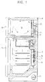
- a prior art refrigerator has a body 14 defining a freezing compartment 15 and a fresh food compartment 1, first and second doors 16, 12 to the freezing compartment 15 and the fresh food compartment 1 respectively, a compressor 19 for compressing refrigerant, an evaporator 11 for generating cool air by evaporating the refrigerant supplied from the compressor 19, and a fan 20 for blowing the cool air generated by the evaporator 11.
- a duct member 3, forming a cool air duct 2, is installed at the back of the fresh food compartment 1.
- the duct member 3 has a plurality of cool air discharge ports 3a opening into the fresh food compartment 1. Cool air blown by the fan 20 flows into the cool air duct 2, and is then discharged into the fresh food compartment 1 through the cool air discharge ports 3a.
- a guide device 13 for guiding the cool air flowing into the cool air duct 2 toward the cool air discharge ports 3a is installed in the cool air duct 2.
- the refrigerator While the refrigerator is operating, frost forms on the evaporator 11, lowering its efficiency. To deal with this, the refrigerator is equipped with a heater 17 for removing the frost. The heater 17 is operated periodically to remove frost that has formed on the evaporator 11.
- the heat generated by the heater 17 during the defrosting operation is transmitted into the fresh food compartment 1. This is undesirable.
- the heat generated by the heater 17 is mainly transmitted through the cool air path. That is, the heat is mainly transmitted to the fresh food compartment 1 through the cool air duct 2 and the cool air discharge ports 3a. Due to the heat transmitted to the fresh food compartment 1, the cooling efficiency of the fresh food compartment 1 is lowered, and the status of the food stored therein cannot be maintained properly.
- the warm ambient air flows into the fresh food compartment 1, mainly into the area adjacent to the evaporator 11.
- the ambient air flows toward the evaporator 11, much more frost forms on the evaporator 11. This means that the defrosting operation must be performed more frequently resulting in more heat flowing from the heater 17 to the fresh food compartment 1.
- a refrigerator according to the present invention is characterised by a closure means comprising a member having an aperture and drive means configured to drive said member parallel to said wall so as to bring the aperture out of and into alignment with opening, thereby blocking and unblocking the opening.
- defrosting control means operable to periodically energise a heater for defrosting the evaporator and operate the drive means so as to block the opening when the heater is energised, is included.
- a door open sensor for sensing opening of a fresh food compartment door
- anti-frosting control means responsive to the door open sensor to operate the drive means so as to block the opening when the fresh food compartment door is opened
- the drive means may comprise a motor and a cam drivingly connected to the motor, in which case the member rests on the cam so as to be moved thereby.
- a spring means is provided for holding the member in contact with the cam.
- the drive means may comprise a motor, a pinion gear drivingly connected to the motor and a rack mounted to the member and engaged by the pinion gear.
- the drive means may comprise a motor mounted to the member, a pinion gear drivingly connected to the motor and a L-shaped rack stationary relative to the wall and engaged by the pinion gear, the rack being arranged such that the member moves perpendicular to the wall as the or each opening becomes blocked.
- an opening/closing device for opening/closing the cool air discharge ports 3a is installed the cool air duct 2.
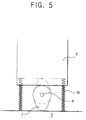
- the opening/closing device includes an opening/closing member 6, a cam 7, and a driving motor 9.
- the opening/closing member 6 is located by channels 4 formed at the duct member 3.
- the opening/closing member 6 is in close contact with the duct member 3.
- the opening/closing member 6 has a plurality of air holes 5 associated with respective the cool discharge ports 3a.
- the cam 7 is disposed under the opening/closing member 6 and supports the opening/closing member 6. The opening/closing member 6 is kept in contact with the cam 7 by its own weight.
- the driving motor 9 is fixed by a bracket (not shown) towards the bottom of the cool air duct 2.
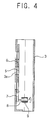
- the cam 7 is mounted on the shaft 8 of the driving motor 9. When the driving motor 9 operates, the cam 7 is rotated, and the opening/closing member 6 is driven up and allowed to fall by the action of the cam 7. When the opening/closing member 6 is moved up, the cool air discharge ports 3a are opened as shown in Figure 4, and when the opening/closing member 6 is falls, the cool air discharge ports 3a are closed by the opening/closing member 6.
- the opening/closing member 6 keeps the cool air discharge ports 3a open, as shown in Figure 4.
- a control part which is not shown, energises the driving motor 9 to rotate the cam 7 so that the opening/closing member 6 falls, closing the cool air discharge ports 3a.
- the opening of the second door 12 is sensed by a sensor (not shown) and the control part responds by energising the driving motor 9 to close the cool air discharge ports 3a as described above.
- the cool air discharge ports 3a are closed during the defrosting operation when the heater 17 is generating heat and when the door 12 opened. Consequently, the transmission of the heat from the heater 17 to the fresh food compartment 1 and the transmission of the outside air to the evaporator when the second door 12 is opened are prevented. Therefore, the lowering of the cooling efficiency is prevented, and the frost caused by the outside air is not generated on the evaporator 11.
- the opening/closing device is equipped with a spring 18 for applying a downward elastic force to the opening/closing member 6.
- the spring 18 connects the bottom of the duct member 3 and the bottom of the opening/closing member 6.
- the opening/closing member 6 held in close contact with the cam 7 by the spring 18, and the up-and-down movement of the opening/closing member 6 due to the rotation of the cam 7 is efficiently performed.
- the opening/closing device includes an opening/closing member 26 formed with a plurality of air holes 25 associated with cool air discharge ports 3a of the duct member 3, a rack 26a formed at the lower part of the opening/closing member 26, a pinion 27 engaged with the rack 26a, and a driving motor 29 for driving the pinion 27.
- the opening/closing member 26 is held in place by channels 24 formed at the duct member 3.
- the opening/closing member 26 When the pinion 27 is rotated by the driving motor 29, the opening/closing member 26 is moved up or down depending on the direction of rotation of the driving motor 29. When the opening/closing member 26 is moved up, the cool air discharge ports 3a are opened, and when the opening/closing member 26 is moved down, the cool air discharge ports 3a are closed.
- the operation of the opening/closing member 26 is the same with that of the embodiment shown in Figures 2 through 4. That is, the opening/closing device closes the cool air discharge ports 3a during the defrosting operation and/or when the second door 12 is opened.
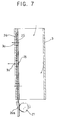
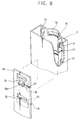
- the opening/closing device includes an opening/closing member 36 formed with a plurality of air holes 35 associated with respective cool air discharge ports 3a of the duct member 3, a driving motor 39 mounted on the opening/closing member 36 by a fixing bracket 39a, and a driving gear 37 installed at the shaft 38 of the driving motor 39.
- a plurality of protrusion parts 46 are formed at the frontal side of the opening/closing member 36.
- the protrusion parts 46 are form-fittingly inserted into the cool air discharge ports 3a when the opening/closing member 36 closes the cool air discharge ports 3a. Therefore, the cool air discharge ports 3a are airtightly closed.
- a guide protrusion 48 is formed at the side of the opening/closing member 36.
- the guide protrusion 48 is inserted into a guide hole 43.
- the duct member 34 is formed with a guide bracket 34 for guiding the movement of the opening/closing member 36 along the vertical direction, and a long hole 41 is formed at the guide bracket 34.
- the long hole 41 is formed vertically, and the upper part thereof is bent toward the front.
- a gear teeth 42 is formed on the inside of the long hole 41.
- the driving gear 37 is inserted into the long hole 41 and engages the gear teeth 42 formed at the long hole 41.
- the driving gear 37 is rotated by the driving motor 39, the driving gear 37 is moved up and down in the long hole 41.
- the driving motor 39 is moved up and down, and the opening/closing member 36 on which the driving motor 39 is fixed is moved up and down.
- the guide bracket 34 is formed with a guide hole 43.
- the guide hole 43 is formed into a shape substantially the same with the shape of the long hole 41.
- the guide protrusion 48 of the opening/closing member 36 is inserted into the guide hole 43, whereby the up-and-down movement of the opening/closing member 36 is efficiently guided.
- the driving gear 37 moves up along the long hole 41, and thereby the opening/closing member 36 moves up.
- the opening/closing member 36 moves toward the front along the long hole 41. Then the opening/closing member 36 comes in contact with the back of duct member 3.
- the protrusion parts 46 are easily inserted into the cool air discharge ports 3a.
- the driving motor 39 is driven in a reverse direction, the opening/closing member 36 is moved down, and the cool air discharge ports 3a are opened.
Landscapes
- Engineering & Computer Science (AREA)
- Chemical & Material Sciences (AREA)
- Combustion & Propulsion (AREA)
- Physics & Mathematics (AREA)
- Mechanical Engineering (AREA)
- Thermal Sciences (AREA)
- General Engineering & Computer Science (AREA)
- Cold Air Circulating Systems And Constructional Details In Refrigerators (AREA)
- Defrosting Systems (AREA)
- Devices That Are Associated With Refrigeration Equipment (AREA)
Abstract
Description
Claims (15)
- A refrigerator including an evaporator (11), a cooling air duct (2) for guiding cooling air from the evaporator (11), the duct (2) having an opening (3a) in a wall (3) thereof into a fresh food compartment (1), characterised by a closure means comprising a member (6; 26; 36) having an aperture (5; 25; 35) and drive means (9, 7; 18; 26, 26a, 27, 29; 37, 38, 39, 41, 42) configured to drive said member (6; 26; 36) parallel to said wall (3) so as to bring the aperture (5; 25; 35) out of and into alignment with opening (3a), thereby blocking and unblocking the opening (3a).
- A refrigerator according to claim 1, including defrosting control means operable to periodically energise a heater (17) for defrosting the evaporator (11) and operate the drive means (9, 7; 18; 26, 27, 29; 37, 38, 39, 41, 42) so as to block the opening (3a) when the heater (17) is energised.
- A refrigerator according to claim 2, including a fresh food compartment door (12), a door open sensor for sensing opening of the fresh food compartment door (12) and anti-frosting control means responsive to the door open sensor to operate the drive means (9, 7; 18; 26, 27, 29; 37, 38, 39, 41, 42) so as to block the opening (3a) when the fresh food compartment door (12) is opened.
- A refrigerator according to claim 1, 2 or 3, wherein there is a plurality of openings (3a) in said wall (3) into the fresh food compartment (1) and said member (6; 26; 36) has an aperture (5; 25; 35) for each of said openings (3a).
- A refrigerator according to any preceding claim, wherein the drive means comprises a motor (9) and a cam (7) drivingly connected to the motor (9), and the member (6) rests on the cam (7) so as to be moved thereby.
- A refrigerator according to claim 5, including a spring means (18) for holding the member (6) in contact with the cam (7).
- A refrigerator according to any one of claims 1 to 4, wherein the drive means comprises a motor (29), a pinion gear (27) drivingly connected to the motor (9) and a rack (26a) mounted to the member (26) and engaged by the pinion gear (27).
- A refrigerator according to any one of claims 1 to 4, wherein the drive means comprises a motor (39) mounted to the member (36), a pinion gear (37) drivingly connected to the motor (39) and a L-shaped rack (42) stationary relative to the wall (3) and engaged by the pinion gear (37), the rack (42) being arranged such that the member (36) moves perpendicular to the wall (3) as the or each opening becomes blocked.
- A refrigerator comprising:a door for opening/closing a cooling compartment;an evaporator for generating cool air to be supplied into said cooling compartment by evaporating refrigerant;a heater for removing frost generated on said evaporator;a duct member for forming a cool air duct into which the cool air generated by said evaporator flows, said duct member being formed with a plurality of cool air discharge ports opened in said cooling compartment; andan opening/closing device including an opening/closing member being in close contact with said duct member, said opening/closing member being formed with air holes corresponding to the cool air discharge ports, a cam being disposed under said opening/closing member, said cam for supporting said opening/closing member, and a motor for driving said cam so that said cool air discharge ports are opened/closed by said opening/closing member, whereinsaid opening/closing device closes the cool air discharge ports during a defrosting operation of said heater and/or when said door is open.
- The refrigerator as claimed in claim 9, further comprising a spring for forcing said opening/closing member so that said opening/closing member is in elastic contact with said cam.
- A refrigerator comprising:a door for opening/closing a cooling compartment;an evaporator for generating cool air to be supplied into said cooling compartment by evaporating refrigerant;a heater for removing frost generated on said evaporator;a duct member for forming a cool air duct into which the cool air generated by said evaporator flows, said duct member being formed with a plurality of cool air discharge ports opened in said cooling compartment; andan opening/closing device including an opening/closing member being in close contact with said duct member, said opening/closing member being formed with air holes corresponding to the cool air discharge ports, a rack being formed in a body with said opening/closing member, a pinion being engaged with said rack, and a motor for driving said pinion so that said cool air discharge ports are opened/closed by said opening/closing member, whereinsaid opening/closing device closes the cool air discharge ports during a defrosting operation of said heater and/or when said door is open.
- A refrigerator comprising:a door for opening/closing a cooling compartment;an evaporator for generating cool air to be supplied into said cooling compartment by evaporating refrigerant;a heater for removing frost generated on said evaporator;a duct member for forming a cool air duct into which the cool air generated by said evaporator flows, said duct member being formed with a plurality of cool air discharge ports opened in said cooling compartment; andan opening/closing device including an opening/closing member being in close contact with said duct member, said opening/closing member being formed with air holes corresponding to the cool air discharge ports, a motor being fixed on said opening/closing member, a driving gear being rotated by said motor, said driving gear being inserted into a long hole formed on said duct member, and a gear part being formed at an inner side of the long hole, said gear part being engaged with said driving gear, said opening/closing device for opening/closing the cool air discharge ports by moving said opening/closing member, whereinsaid opening/closing device closes the cool air discharge ports during a defrosting operation of said heater and/or when said door is open.
- The refrigerator as claimed in claim 12, wherein said opening/closing member is formed with protrusion parts being form-fittingly inserted into the cool air discharge ports when the cool air discharge ports are closed thereby.
- The refrigerator as claimed in claim 13, wherein the long hole is bent so that said protrusion parts is moved to be inserted into the cool air discharge ports when said opening/closing member is operated to close the cool air discharge ports.
- The refrigerator as claimed in claim 14, wherein said duct member is formed with a guide hole for guiding said opening/closing member, and said opening/closing member is formed with a guide protrusion being inserted into the guide hole.
Applications Claiming Priority (8)
| Application Number | Priority Date | Filing Date | Title |
|---|---|---|---|
| KR9714298 | 1997-04-18 | ||
| KR1019970014298A KR100219429B1 (en) | 1997-04-18 | 1997-04-18 | Cool air supply control device of a refrigerator |
| KR9734355 | 1997-07-23 | ||
| KR2019970019403U KR200151224Y1 (en) | 1997-07-23 | 1997-07-23 | Cool air supply control device of a refrigerator |
| KR1019970034355A KR100229639B1 (en) | 1997-07-23 | 1997-07-23 | Cold air discharge control method of the refrigerator |
| KR9719403U | 1997-07-23 | ||
| KR2019970020623U KR200154124Y1 (en) | 1997-07-31 | 1997-07-31 | Cold air discharge controller |
| KR9720623U | 1997-07-31 |
Publications (2)
| Publication Number | Publication Date |
|---|---|
| EP0872696A2 true EP0872696A2 (en) | 1998-10-21 |
| EP0872696A3 EP0872696A3 (en) | 1999-06-16 |
Family
ID=27483198
Family Applications (1)
| Application Number | Title | Priority Date | Filing Date |
|---|---|---|---|
| EP98302898A Withdrawn EP0872696A3 (en) | 1997-04-18 | 1998-04-15 | Refrigerator |
Country Status (4)
| Country | Link |
|---|---|
| US (1) | US6032480A (en) |
| EP (1) | EP0872696A3 (en) |
| JP (1) | JP2918530B2 (en) |
| CN (1) | CN1116571C (en) |
Cited By (7)
| Publication number | Priority date | Publication date | Assignee | Title |
|---|---|---|---|---|
| EP0878675A3 (en) * | 1997-05-15 | 1999-07-14 | Samsung Electronics Co., Ltd. | Refrigerator |
| WO2004109201A1 (en) * | 2003-06-05 | 2004-12-16 | Multibrás S.A. Eletrodmésticos | Airflow control system in refrigerators and freezers |
| EP1284398A4 (en) * | 2000-05-22 | 2005-05-18 | Matsushita Refrigeration | FRIDGE |
| US7036332B2 (en) | 2003-12-01 | 2006-05-02 | Dometic Sweden Ab | Heat exchanger arrangement |
| US7237402B2 (en) | 2003-12-01 | 2007-07-03 | Dometic Sweden Ab | Refrigerator and method |
| WO2008135584A3 (en) * | 2007-05-07 | 2009-05-07 | Bsh Bosch Siemens Hausgeraete | Cooling device |
| WO2016037719A1 (en) * | 2014-09-11 | 2016-03-17 | Arcelik Anonim Sirketi | A refrigerator comprising a humidity and temperature controlled compartment |
Families Citing this family (22)
| Publication number | Priority date | Publication date | Assignee | Title |
|---|---|---|---|---|
| KR100305321B1 (en) * | 1999-07-21 | 2001-09-13 | 전주범 | refrigerator as cooling air curtain |
| CN1177188C (en) * | 2001-08-31 | 2004-11-24 | Lg电子株式会社 | Cooling air circulation unit in refrigerator |
| US6634181B2 (en) * | 2001-08-31 | 2003-10-21 | Lg Electronics Inc. | Cooling air supply apparatus of refrigerator |
| US6722144B2 (en) | 2001-10-03 | 2004-04-20 | General Electric Company | Cylindrical airflow damper |
| KR100498386B1 (en) * | 2002-12-06 | 2005-07-01 | 엘지전자 주식회사 | Apparatus for supply the cool air of refrigerator |
| KR100619757B1 (en) * | 2004-11-09 | 2006-09-07 | 엘지전자 주식회사 | Refrigerator with basket lift device and control method of basket lift device of the refrigerator |
| US7926298B2 (en) * | 2007-07-19 | 2011-04-19 | Whirlpool Corporation | Variable position air damper for a refrigerator |
| DE102008021375A1 (en) * | 2008-04-29 | 2009-11-05 | BSH Bosch und Siemens Hausgeräte GmbH | Refrigeration unit with pressure compensation valve |
| JP5523968B2 (en) * | 2010-07-28 | 2014-06-18 | 株式会社東芝 | refrigerator |
| JP5644378B2 (en) * | 2010-11-02 | 2014-12-24 | 富士電機株式会社 | Deck pan mounting structure |
| KR20130129795A (en) * | 2012-05-21 | 2013-11-29 | 동부대우전자 주식회사 | Refrigerator |
| CN104764270B (en) * | 2014-01-03 | 2018-05-18 | 苏州三星电子有限公司 | A kind of wind cooling refrigerator and its air door |
| JP2014145584A (en) * | 2014-04-08 | 2014-08-14 | Toshiba Corp | Refrigerator |
| KR102517410B1 (en) * | 2016-03-25 | 2023-04-03 | 엘지전자 주식회사 | Refrigerator |
| CN107240197A (en) * | 2016-03-28 | 2017-10-10 | 山东新北洋信息技术股份有限公司 | A kind of express mail cabinet |
| CN106247735B (en) * | 2016-07-12 | 2019-08-13 | 青岛海尔股份有限公司 | a refrigerator |
| CN107560300B (en) * | 2017-09-20 | 2018-07-17 | 河南康拜恩电器股份有限公司 | A kind of refrigerator with matter storage lattice |
| CN109798720A (en) * | 2017-11-16 | 2019-05-24 | 合肥华凌股份有限公司 | The damper assemblies of refrigeration equipment and refrigeration equipment with it |
| CN109798719A (en) * | 2017-11-16 | 2019-05-24 | 合肥华凌股份有限公司 | The control method and control device and equipment of damper assemblies |
| CN109798710A (en) * | 2017-11-16 | 2019-05-24 | 合肥华凌股份有限公司 | The damper assemblies of refrigeration equipment and refrigeration equipment with it |
| CN111750597A (en) * | 2019-03-26 | 2020-10-09 | 青岛海尔电冰箱有限公司 | Refrigeration device |
| US11002476B2 (en) * | 2019-04-01 | 2021-05-11 | Haier Us Appliance Solutions, Inc. | Ice maker having a splash cover |
Family Cites Families (8)
| Publication number | Priority date | Publication date | Assignee | Title |
|---|---|---|---|---|
| US2660036A (en) * | 1950-09-01 | 1953-11-24 | Leonard O Moore | Refrigerator having door operated valve means |
| US4282720A (en) * | 1979-08-29 | 1981-08-11 | General Electric Co. | Refrigerator air baffle control |
| US4688393A (en) * | 1986-06-03 | 1987-08-25 | Whirlpool Corporation | Power switch and baffle assembly for a refrigerator |
| US4732010A (en) * | 1986-06-03 | 1988-03-22 | Whirlpool Corporation | Power switch and baffle assembly having unidirectional drive motor for a refrigerator |
| KR970009025B1 (en) * | 1990-09-26 | 1997-06-03 | Samsung Electronics Co Ltd | Control arrangements for refrigeration room temperature of refrigerators |
| JPH04136487A (en) * | 1990-09-28 | 1992-05-11 | Hitachi Ltd | Variable displacement compressor |
| JPH04268183A (en) * | 1991-02-21 | 1992-09-24 | Fujitsu General Ltd | electric refrigerator |
| US5490395A (en) * | 1994-11-21 | 1996-02-13 | Whirlpool Corporation | Air baffle for a refrigerator |
-
1998
- 1998-03-12 JP JP10061556A patent/JP2918530B2/en not_active Expired - Fee Related
- 1998-04-08 CN CN98106217A patent/CN1116571C/en not_active Expired - Fee Related
- 1998-04-09 US US09/057,489 patent/US6032480A/en not_active Expired - Fee Related
- 1998-04-15 EP EP98302898A patent/EP0872696A3/en not_active Withdrawn
Non-Patent Citations (1)
| Title |
|---|
| None |
Cited By (8)
| Publication number | Priority date | Publication date | Assignee | Title |
|---|---|---|---|---|
| EP0878675A3 (en) * | 1997-05-15 | 1999-07-14 | Samsung Electronics Co., Ltd. | Refrigerator |
| US6014865A (en) * | 1997-05-15 | 2000-01-18 | Samsung Electronics Co., Ltd. | Refrigerator having a device for preventing flow of air between an evaporator and a cooling compartment |
| EP1284398A4 (en) * | 2000-05-22 | 2005-05-18 | Matsushita Refrigeration | FRIDGE |
| WO2004109201A1 (en) * | 2003-06-05 | 2004-12-16 | Multibrás S.A. Eletrodmésticos | Airflow control system in refrigerators and freezers |
| US7036332B2 (en) | 2003-12-01 | 2006-05-02 | Dometic Sweden Ab | Heat exchanger arrangement |
| US7237402B2 (en) | 2003-12-01 | 2007-07-03 | Dometic Sweden Ab | Refrigerator and method |
| WO2008135584A3 (en) * | 2007-05-07 | 2009-05-07 | Bsh Bosch Siemens Hausgeraete | Cooling device |
| WO2016037719A1 (en) * | 2014-09-11 | 2016-03-17 | Arcelik Anonim Sirketi | A refrigerator comprising a humidity and temperature controlled compartment |
Also Published As
| Publication number | Publication date |
|---|---|
| CN1116571C (en) | 2003-07-30 |
| JP2918530B2 (en) | 1999-07-12 |
| EP0872696A3 (en) | 1999-06-16 |
| JPH10288443A (en) | 1998-10-27 |
| CN1197193A (en) | 1998-10-28 |
| US6032480A (en) | 2000-03-07 |
Similar Documents
| Publication | Publication Date | Title |
|---|---|---|
| EP0872696A2 (en) | Refrigerator | |
| EP0878675B1 (en) | Refrigerator | |
| US5987904A (en) | Refrigerator with a device for opening/closing cool air discharge ports | |
| EP0893660B1 (en) | Refrigerator | |
| US5974814A (en) | Refrigerator capable of preventing heat exchange between an evaporator and outside warm air | |
| US5826441A (en) | Refrigerator having a device for generating air curtains | |
| US20080148765A1 (en) | Refrigerated Drawer Structure | |
| KR100235441B1 (en) | Cool air circulation method and device of a refrigerator | |
| EP0287390A2 (en) | Vending machine with temperature control | |
| KR100595434B1 (en) | Refrigerator | |
| KR100212864B1 (en) | Refrigerator | |
| KR100195451B1 (en) | A refrigerator | |
| KR100288428B1 (en) | Air curtain control method of refrigerator | |
| JPH03109695A (en) | Automatic vending machine | |
| KR100193707B1 (en) | Evaporation room shutoff device and control method of refrigerator having same | |
| KR100229640B1 (en) | Cold air discharge control method of refrigerator | |
| KR200207424Y1 (en) | Refrigerator | |
| JP3338108B2 (en) | refrigerator | |
| KR100235442B1 (en) | How to control temperature of refrigerator | |
| KR100237068B1 (en) | Cold Storage Compensator | |
| KR100220394B1 (en) | Cooling air supplying structure for a refrigerator | |
| KR20070040120A (en) | Cold Chopper on Refrigerator Home Bar | |
| KR100208088B1 (en) | Auto shutter control method of refrigerator | |
| KR970004266Y1 (en) | Cooling air leakage preventing device of a showcase | |
| JP2000028256A (en) | Cold storage chamber |
Legal Events
| Date | Code | Title | Description |
|---|---|---|---|
| PUAI | Public reference made under article 153(3) epc to a published international application that has entered the european phase |
Free format text: ORIGINAL CODE: 0009012 |
|
| AK | Designated contracting states |
Kind code of ref document: A2 Designated state(s): DE FR GB |
|
| AX | Request for extension of the european patent |
Free format text: AL;LT;LV;MK;RO;SI |
|
| PUAL | Search report despatched |
Free format text: ORIGINAL CODE: 0009013 |
|
| AK | Designated contracting states |
Kind code of ref document: A3 Designated state(s): AT BE CH CY DE DK ES FI FR GB GR IE IT LI LU MC NL PT SE |
|
| AX | Request for extension of the european patent |
Free format text: AL;LT;LV;MK;RO;SI |
|
| 17P | Request for examination filed |
Effective date: 19991214 |
|
| AKX | Designation fees paid |
Free format text: AT BE CH LI |
|
| RBV | Designated contracting states (corrected) |
Designated state(s): DE FR GB |
|
| REG | Reference to a national code |
Ref country code: DE Ref legal event code: 8566 |
|
| STAA | Information on the status of an ep patent application or granted ep patent |
Free format text: STATUS: THE APPLICATION IS DEEMED TO BE WITHDRAWN |
|
| 18D | Application deemed to be withdrawn |
Effective date: 20001101 |