EP0872705B1 - Dispositif de retenue pour neutraliser une mine autopropulsée - Google Patents
Dispositif de retenue pour neutraliser une mine autopropulsée Download PDFInfo
- Publication number
- EP0872705B1 EP0872705B1 EP98106896A EP98106896A EP0872705B1 EP 0872705 B1 EP0872705 B1 EP 0872705B1 EP 98106896 A EP98106896 A EP 98106896A EP 98106896 A EP98106896 A EP 98106896A EP 0872705 B1 EP0872705 B1 EP 0872705B1
- Authority
- EP
- European Patent Office
- Prior art keywords
- warhead
- catching device
- net
- projectiles
- launched
- Prior art date
- Legal status (The legal status is an assumption and is not a legal conclusion. Google has not performed a legal analysis and makes no representation as to the accuracy of the status listed.)
- Expired - Lifetime
Links
- 230000003472 neutralizing effect Effects 0.000 title 1
- 239000002360 explosive Substances 0.000 claims description 6
- 230000001681 protective effect Effects 0.000 claims description 5
- 230000001154 acute effect Effects 0.000 claims 1
- 230000000087 stabilizing effect Effects 0.000 claims 1
- 230000001960 triggered effect Effects 0.000 claims 1
- 239000003380 propellant Substances 0.000 description 4
- XLYOFNOQVPJJNP-UHFFFAOYSA-N water Substances O XLYOFNOQVPJJNP-UHFFFAOYSA-N 0.000 description 4
- 238000007664 blowing Methods 0.000 description 2
- 230000005484 gravity Effects 0.000 description 2
- 238000000034 method Methods 0.000 description 2
- 238000005422 blasting Methods 0.000 description 1
- 238000011161 development Methods 0.000 description 1
- 230000018109 developmental process Effects 0.000 description 1
- 238000004880 explosion Methods 0.000 description 1
- 239000011888 foil Substances 0.000 description 1
- 230000000977 initiatory effect Effects 0.000 description 1
- 239000004570 mortar (masonry) Substances 0.000 description 1
- 238000007789 sealing Methods 0.000 description 1
- 230000035939 shock Effects 0.000 description 1
Images

Classifications
-
- F—MECHANICAL ENGINEERING; LIGHTING; HEATING; WEAPONS; BLASTING
- F41—WEAPONS
- F41H—ARMOUR; ARMOURED TURRETS; ARMOURED OR ARMED VEHICLES; MEANS OF ATTACK OR DEFENCE, e.g. CAMOUFLAGE, IN GENERAL
- F41H13/00—Means of attack or defence not otherwise provided for
- F41H13/0006—Ballistically deployed systems for restraining persons or animals, e.g. ballistically deployed nets
-
- B—PERFORMING OPERATIONS; TRANSPORTING
- B63—SHIPS OR OTHER WATERBORNE VESSELS; RELATED EQUIPMENT
- B63G—OFFENSIVE OR DEFENSIVE ARRANGEMENTS ON VESSELS; MINE-LAYING; MINE-SWEEPING; SUBMARINES; AIRCRAFT CARRIERS
- B63G7/00—Mine-sweeping; Vessels characterised thereby
- B63G7/02—Mine-sweeping means, Means for destroying mines
-
- F—MECHANICAL ENGINEERING; LIGHTING; HEATING; WEAPONS; BLASTING
- F41—WEAPONS
- F41H—ARMOUR; ARMOURED TURRETS; ARMOURED OR ARMED VEHICLES; MEANS OF ATTACK OR DEFENCE, e.g. CAMOUFLAGE, IN GENERAL
- F41H11/00—Defence installations; Defence devices
- F41H11/12—Means for clearing land minefields; Systems specially adapted for detection of landmines
- F41H11/16—Self-propelled mine-clearing vehicles; Mine-clearing devices attachable to vehicles
- F41H11/28—Self-propelled mine-clearing vehicles; Mine-clearing devices attachable to vehicles using brushing or sweeping means or dozers to push mines lying on a surface aside; using means for removing mines intact from a surface
-
- F—MECHANICAL ENGINEERING; LIGHTING; HEATING; WEAPONS; BLASTING
- F41—WEAPONS
- F41H—ARMOUR; ARMOURED TURRETS; ARMOURED OR ARMED VEHICLES; MEANS OF ATTACK OR DEFENCE, e.g. CAMOUFLAGE, IN GENERAL
- F41H11/00—Defence installations; Defence devices
- F41H11/12—Means for clearing land minefields; Systems specially adapted for detection of landmines
- F41H11/16—Self-propelled mine-clearing vehicles; Mine-clearing devices attachable to vehicles
- F41H11/32—Decoy or sacrificial vehicles; Decoy or sacrificial devices attachable to vehicles
-
- F—MECHANICAL ENGINEERING; LIGHTING; HEATING; WEAPONS; BLASTING
- F42—AMMUNITION; BLASTING
- F42B—EXPLOSIVE CHARGES, e.g. FOR BLASTING, FIREWORKS, AMMUNITION
- F42B12/00—Projectiles, missiles or mines characterised by the warhead, the intended effect, or the material
- F42B12/02—Projectiles, missiles or mines characterised by the warhead, the intended effect, or the material characterised by the warhead or the intended effect
- F42B12/36—Projectiles, missiles or mines characterised by the warhead, the intended effect, or the material characterised by the warhead or the intended effect for dispensing materials; for producing chemical or physical reaction; for signalling ; for transmitting information
- F42B12/56—Projectiles, missiles or mines characterised by the warhead, the intended effect, or the material characterised by the warhead or the intended effect for dispensing materials; for producing chemical or physical reaction; for signalling ; for transmitting information for dispensing discrete solid bodies
- F42B12/58—Cluster or cargo ammunition, i.e. projectiles containing one or more submissiles
- F42B12/66—Chain-shot, i.e. the submissiles being interconnected by chains or the like
Definitions
- the invention relates to a catching device for combating drift mines and anchor mines according to the preamble of claim 1.
- the safety gear consists of a few and simple and in particular inexpensive Divide.
- the safety gear needs a small storage space and is thereby in containers that can be dropped by helicopters or airplanes or in Drones or even in ammunition, such as mortar ammunition or carrier bullets easily accommodate. Triggering of the safety gear in the target area is either sensor, time or remote controlled.
- the self-sufficient safety gear is essential for the invention, since after the launch all functions take place automatically given the ship's safety.
- This relates in particular to the release of the warhead's explosive charge and the subsequent blowing up of the blowing mine.
- the initiation is from Ship provided, so remote controlled.
- the remote control of the blasting can generally be provided.
- warhead 1 which can be fired via a ship's gun, not shown from a fuselage 2 and a protective hood 34 with ogive 4.
- an explosive charge 20 on the bottom Arranged in the fuselage 2 are an explosive charge 20 on the bottom, a catch winch 22 with Einholleine 23, a gas generator 24 with shock-responsive Igniter 25, a signal processing 26, a central tube 27 and one connected thereto Cup 28, the central tube 27 serving as the gas line of the gas generator 24 is trained.
- the central tube 27 has a valve 29 on the cup side.
- the warhead 1 To better illustrate the function of the warhead 1 is one of the air bags 33.1 inflated via the central tube 27 or the gas generator 24.
- the one in Sector-shaped airbag 33.1 seen in cross section swivels the discharge tube 32.1 to the outside by 45 °.
- the discharge pipe 32 is located through a not drawn stop in its end position.
- each of the discharge pipes 32 there is a gas generator 39 according to the high-low pressure system and a missile 37 with a tow line 38 and one over an opening 8 leading out of the discharge pipe 32 is arranged.
- a single gas generator can be provided.
- the bowl 28 contains a folded floating net 10 with six towing lines 38 arranged thereon.
- the igniter 25 When it hits water, the igniter 25 is initiated. Pressure then builds up via the central tube 27 and the valve 29 in the cup 28. By tensile stresses at the predetermined breaking point 35, this finally travels and the protective hood 34 is repelled by the hull 2 together with the ogive 4 and sinks in Water.
- valve 29 then closes due to the control by the signal processing 26th
- the air bags 33 and 41 orient the warhead 1 together with the deep lying center of gravity 45 with respect to "above and below”. This is the airbag or an annular buoyancy body 41 also through the gas generator 24 inflated.
- the signal processing 26 then causes the ignition of the respective gas generators 39 of the discharge pipes 32 and thus the relatively slow discharge of the projectile in the discharge tubes 32 stored missile 37.
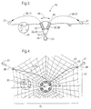
- the relative loosely arranged pull lines 38 take place with a certain time delay Spreading the network 10 over a propellant mine 30.
- the gravity of the missiles 37 lets them dip into the water and sink. This will make the network 10 placed around the lead mine 30.
- a warhead 40 is already over a target area discarded.
- the warhead 40 consists of the six discharge tubes 32 Towing lines 38, gas generator 39 and missile 37. Between each exhaust pipe 32, a network segment 42 is arranged. The network segments 42 are over the pull lines 38 connected to each other.
- An inflated airbag 45 stabilizes and causes the warhead 40 in the water during the inflation process, unfolding the launch tubes 41 in the direction of Double arrow 46.
- the pull lines 38 are connected at the start to the hauling winch 22.
- the missiles When the network segments 42 are ejected from the launch tubes 32, the missiles pull 37 the pull lines 38 with the network segments 42 radially outwards. The Network segments 42 thus fan out and form the unfolded network all over 10. The missiles 37 - they are non-floating - pull the net 10 over the Driving mine 30. The haul-in winch 22 hauls in the pull lines 38. The explosion follows the propellant mine 30 in the manner described for FIG. 1.
Landscapes
- Engineering & Computer Science (AREA)
- General Engineering & Computer Science (AREA)
- Radar, Positioning & Navigation (AREA)
- Remote Sensing (AREA)
- Chemical & Material Sciences (AREA)
- Combustion & Propulsion (AREA)
- Aviation & Aerospace Engineering (AREA)
- Aiming, Guidance, Guns With A Light Source, Armor, Camouflage, And Targets (AREA)
- Radar Systems Or Details Thereof (AREA)
Claims (7)
- Dispositif d'interception (1) pour combattre des mines flottantes (30), caractérisé par une tête militaire (1) qui peut être tirée ou larguée à proximité d'une mine flottante (30) et qui est susceptible de flotter, par des missiles (37), pouvant être lancés par la tête militaire (1), pour déployer un filet (10) au-dessus de la mine flottante (30), comportant un treuil de halage (22) pour haler la mine flottante (30) au moyen d'une corde de halage (23 ; 38) reliée au filet (10), et comportant une charge explosive (20) disposée dans la tête militaire (1) et pouvant être déclenchée, afin de détruire ou d'allumer la mine flottante (30).
- Dispositif d'interception selon la revendication 1, caractérisé en ce que la tête militaire (1) comporte des moyens de stabilisation, tels qu'un ou plusieurs corps flottants (33 ; 41) qui maintiennent l'axe vertical de la tête militaire (1) pratiquement à angle droit par rapport au plan des vagues.
- Dispositif d'interception selon la revendication 1, caractérisé en ce que le lancement du missile (37) intervient au point culminant de la vague.
- Dispositif d'interception selon la revendication 1, caractérisé en ce que la tête militaire (1) comporte au moins un corps de sustentation (33 ; 41).
- Dispositif d'interception selon la revendication 1, caractérisé en ce que les tubes de lancement (32) avec les missiles (37) sont uniformément répartis sur le pourtour de la tête militaire (1) et disposés pivotants, l'angle de tir des missiles (37) s'étend suivant un angle aigu par rapport à l'axe vertical de la tête militaire et chaque missile lui-même entraíné ou pouvant être tiré est relié au filet (10) par un câble de traction (38).
- Dispositif d'interception selon la revendication 1, caractérisé en ce que le filet (10) d'une seule pièce, tendu ou déployé, est divisé par les câbles de traction (38) en secteurs ou segments de filet (42) de même dimension.
- Dispositif d'interception selon la revendication 1, caractérisé en ce que la tête militaire (1) possède côté fond la charge explosive (20), les groupes suivants se raccordant, à partir de la charge explosive (20), en direction de la tête de la tête militaire (1) :un traitement des signaux (26),un générateur de gaz (24) pour détacher une ogive de protection (34) ou pour gonfler des corps de sustentation (33 ; 41),un dispositif de lancement pour les missiles (37),un treuil de halage (22),au moins un dispositif de sustentation (33 ; 41) etune nacelle (28) pour supporter le filet (10) replié etune antenne (12) à l'intérieur d'une ogive de protection (34).
Applications Claiming Priority (2)
| Application Number | Priority Date | Filing Date | Title |
|---|---|---|---|
| DE19716512A DE19716512B4 (de) | 1997-04-19 | 1997-04-19 | Fangvorrichtung zur Bekämpfung von Treibminen |
| DE19716512 | 1997-04-19 |
Publications (3)
| Publication Number | Publication Date |
|---|---|
| EP0872705A2 EP0872705A2 (fr) | 1998-10-21 |
| EP0872705A3 EP0872705A3 (fr) | 2000-05-10 |
| EP0872705B1 true EP0872705B1 (fr) | 2003-03-19 |
Family
ID=7827085
Family Applications (1)
| Application Number | Title | Priority Date | Filing Date |
|---|---|---|---|
| EP98106896A Expired - Lifetime EP0872705B1 (fr) | 1997-04-19 | 1998-04-16 | Dispositif de retenue pour neutraliser une mine autopropulsée |
Country Status (5)
| Country | Link |
|---|---|
| EP (1) | EP0872705B1 (fr) |
| DE (2) | DE19716512B4 (fr) |
| DK (1) | DK0872705T3 (fr) |
| ES (1) | ES2195216T3 (fr) |
| NO (1) | NO981704L (fr) |
Cited By (15)
| Publication number | Priority date | Publication date | Assignee | Title |
|---|---|---|---|---|
| US7624682B2 (en) | 2001-08-23 | 2009-12-01 | Raytheon Company | Kinetic energy rod warhead with lower deployment angles |
| US7624683B2 (en) | 2001-08-23 | 2009-12-01 | Raytheon Company | Kinetic energy rod warhead with projectile spacing |
| US7726244B1 (en) | 2003-10-14 | 2010-06-01 | Raytheon Company | Mine counter measure system |
| US8042449B2 (en) | 2006-02-09 | 2011-10-25 | Foster-Miller, Inc. | Vehicle protection system |
| US8245621B2 (en) | 2008-04-16 | 2012-08-21 | Qinetiq North America | Vehicle and structure shield |
| US8281702B2 (en) | 2006-02-09 | 2012-10-09 | Foster-Miller, Inc. | Protection system |
| US8443709B2 (en) | 2008-04-16 | 2013-05-21 | QinetiQ North America, Inc. | Vehicle and structure shield hard point |
| US8453552B2 (en) | 2008-04-16 | 2013-06-04 | QinetiQ North America, Inc. | Method of designing an RPG shield |
| US8464627B2 (en) | 2008-04-16 | 2013-06-18 | QinetiQ North America, Inc. | Vehicle and structure shield with improved hard points |
| US8468927B2 (en) | 2008-04-16 | 2013-06-25 | QinetiQ North America, Inc. | Vehicle and structure shield with a cable frame |
| US8607685B2 (en) | 2008-04-16 | 2013-12-17 | QinetiQ North America, Inc. | Load sharing hard point net |
| US8615851B2 (en) | 2008-04-16 | 2013-12-31 | Foster-Miller, Inc. | Net patching devices |
| US8677882B2 (en) | 2010-09-08 | 2014-03-25 | QinetiQ North America, Inc. | Vehicle and structure shield with flexible frame |
| US8733225B1 (en) | 2008-04-16 | 2014-05-27 | QinteiQ Nörth America, Inc. | RPG defeat method and system |
| US8813631B1 (en) | 2013-02-13 | 2014-08-26 | Foster-Miller, Inc. | Vehicle and structure film/hard point shield |
Families Citing this family (9)
| Publication number | Priority date | Publication date | Assignee | Title |
|---|---|---|---|---|
| DE19901083C1 (de) | 1999-01-14 | 2000-03-30 | Mak System Gmbh | Verfahren und Vorrichtung zur Vernichtung treibender Seeminen |
| US7415917B2 (en) * | 2002-08-29 | 2008-08-26 | Raytheon Company | Fixed deployed net for hit-to-kill vehicle |
| US7441511B2 (en) | 2005-02-28 | 2008-10-28 | Foster-Miller, Inc. | Watercraft arresting system |
| DE102007025563B4 (de) * | 2007-05-31 | 2010-07-15 | Rheinmetall Waffe Munition Gmbh | Fangsystem |
| US8245620B2 (en) | 2008-04-16 | 2012-08-21 | QinetiQ North America, Inc. | Low breaking strength vehicle and structure shield net/frame arrangement |
| US9581417B2 (en) * | 2016-04-22 | 2017-02-28 | Jui-Fu Tseng | Concealed net throwing device |
| US10197365B1 (en) * | 2017-10-20 | 2019-02-05 | The United States Of America As Represented By The Secretary Of The Army | Scalable effects net warhead |
| CN113251872A (zh) * | 2021-03-15 | 2021-08-13 | 中北大学 | 一种反无人机的软毁伤弹药结构 |
| CN121230572A (zh) * | 2023-02-06 | 2025-12-30 | 吴俊颖 | 一种组合式携网弹头 |
Family Cites Families (5)
| Publication number | Priority date | Publication date | Assignee | Title |
|---|---|---|---|---|
| FR864536A (fr) * | 1939-12-19 | 1941-04-29 | Dispositif pour le dragage des mines marines et la protection des navires contre les engins explosifs | |
| DE3624409C1 (en) * | 1986-07-18 | 1987-12-17 | Bundesrep Deutschland | Sea-mine destroyer device |
| FR2734350A1 (fr) * | 1987-04-22 | 1996-11-22 | Thomson Brandt Armements | Procede et projectile de neutralisation de cibles, notamment d'helicopteres ou de navires |
| DE4439762C1 (de) * | 1994-11-07 | 1995-12-07 | Daimler Benz Aerospace Ag | Personen-Fernfessel |
| JP2576810B2 (ja) * | 1994-12-22 | 1997-01-29 | 日本電気株式会社 | 水上危険物処分装置 |
-
1997
- 1997-04-19 DE DE19716512A patent/DE19716512B4/de not_active Expired - Fee Related
-
1998
- 1998-04-16 DE DE59807509T patent/DE59807509D1/de not_active Expired - Fee Related
- 1998-04-16 DK DK98106896T patent/DK0872705T3/da active
- 1998-04-16 NO NO981704A patent/NO981704L/no not_active Application Discontinuation
- 1998-04-16 EP EP98106896A patent/EP0872705B1/fr not_active Expired - Lifetime
- 1998-04-16 ES ES98106896T patent/ES2195216T3/es not_active Expired - Lifetime
Cited By (22)
| Publication number | Priority date | Publication date | Assignee | Title |
|---|---|---|---|---|
| US7624683B2 (en) | 2001-08-23 | 2009-12-01 | Raytheon Company | Kinetic energy rod warhead with projectile spacing |
| US7624682B2 (en) | 2001-08-23 | 2009-12-01 | Raytheon Company | Kinetic energy rod warhead with lower deployment angles |
| US7726244B1 (en) | 2003-10-14 | 2010-06-01 | Raytheon Company | Mine counter measure system |
| US8281702B2 (en) | 2006-02-09 | 2012-10-09 | Foster-Miller, Inc. | Protection system |
| US8042449B2 (en) | 2006-02-09 | 2011-10-25 | Foster-Miller, Inc. | Vehicle protection system |
| US8141470B1 (en) | 2006-02-09 | 2012-03-27 | Foster-Miller, Inc. | Vehicle protection method |
| US8539875B1 (en) | 2006-02-09 | 2013-09-24 | Foster-Miller, Inc. | Protection system |
| US8464627B2 (en) | 2008-04-16 | 2013-06-18 | QinetiQ North America, Inc. | Vehicle and structure shield with improved hard points |
| US8615851B2 (en) | 2008-04-16 | 2013-12-31 | Foster-Miller, Inc. | Net patching devices |
| US8453552B2 (en) | 2008-04-16 | 2013-06-04 | QinetiQ North America, Inc. | Method of designing an RPG shield |
| US8245622B2 (en) | 2008-04-16 | 2012-08-21 | QinetiQ North America, Inc. | Vehicle and structure shield method |
| US8468927B2 (en) | 2008-04-16 | 2013-06-25 | QinetiQ North America, Inc. | Vehicle and structure shield with a cable frame |
| US8245621B2 (en) | 2008-04-16 | 2012-08-21 | Qinetiq North America | Vehicle and structure shield |
| US8607685B2 (en) | 2008-04-16 | 2013-12-17 | QinetiQ North America, Inc. | Load sharing hard point net |
| US8443709B2 (en) | 2008-04-16 | 2013-05-21 | QinetiQ North America, Inc. | Vehicle and structure shield hard point |
| US9052167B2 (en) | 2008-04-16 | 2015-06-09 | Foster-Miller, Inc. | RPG defeat method and system |
| US8733225B1 (en) | 2008-04-16 | 2014-05-27 | QinteiQ Nörth America, Inc. | RPG defeat method and system |
| US8783156B1 (en) | 2008-04-16 | 2014-07-22 | Foster-Miller, Inc. | Vehicle and structure shield with a cable frame |
| US8910349B1 (en) | 2008-04-16 | 2014-12-16 | Foster Miller, Inc. | Net patching devices |
| US8677882B2 (en) | 2010-09-08 | 2014-03-25 | QinetiQ North America, Inc. | Vehicle and structure shield with flexible frame |
| US8813631B1 (en) | 2013-02-13 | 2014-08-26 | Foster-Miller, Inc. | Vehicle and structure film/hard point shield |
| US9027457B1 (en) | 2013-02-13 | 2015-05-12 | Foster-Miller, Inc. | Vehicle and structure film/hard point shield |
Also Published As
| Publication number | Publication date |
|---|---|
| DE19716512B4 (de) | 2004-04-15 |
| NO981704L (no) | 1998-10-20 |
| EP0872705A2 (fr) | 1998-10-21 |
| NO981704D0 (no) | 1998-04-16 |
| ES2195216T3 (es) | 2003-12-01 |
| DE19716512A1 (de) | 1998-10-22 |
| EP0872705A3 (fr) | 2000-05-10 |
| DE59807509D1 (de) | 2003-04-24 |
| DK0872705T3 (da) | 2003-07-14 |
Similar Documents
| Publication | Publication Date | Title |
|---|---|---|
| EP0872705B1 (fr) | Dispositif de retenue pour neutraliser une mine autopropulsée | |
| US8127683B2 (en) | Weapon and weapon system employing the same | |
| RU2293281C2 (ru) | Снаряд для метания и способы его использования | |
| EP0794405A1 (fr) | Procédé et dispositif pour disperser une charge utile de gros calibre au-dessus d'un objectif | |
| US4744301A (en) | Safer and simpler cluster bomb | |
| DE3322927A1 (de) | Von einem lastengeschoss oder flugkoerper abwerfbarer geschosskopf | |
| DE3626434C2 (fr) | ||
| DE3806731C2 (fr) | ||
| DE3617429A1 (de) | Verfahren zum Bekämpfen von U-Booten und Wirkkörper zum Ausüben des Verfahrens | |
| DE19543757C2 (de) | Verfahren zur Bekämpfung von Seeminen | |
| DE19528112C1 (de) | Munition | |
| US5834682A (en) | Radar signal cartridge | |
| DE102005043078B4 (de) | Suchzündermunition | |
| DE3920016C2 (fr) | ||
| DE3318018C1 (de) | Verfahren zum Bekaempfen von Zielobjekten mittels eines im Wasser beschleunigbaren Projektils und Vorrichtung zum Ausueben des Verfahrens | |
| EP0698774B1 (fr) | Projectile stabilisé par rotation et comportant une charge utile | |
| EP0963907B1 (fr) | Dispositif de retenue pour neutraliser des mines | |
| DE3148167A1 (de) | Abwurfkoerper in form einer mine zur bekaempfung von bodenzielen | |
| DE3920017C2 (fr) | ||
| DE3936065C2 (de) | Mine, insbesondere Landmine | |
| AT38784B (de) | Torpedo. | |
| EP3303982B1 (fr) | Munition fumigène | |
| DE3430498C1 (de) | Verfahren zum Außer-Gefecht-Setzen von Minen sowie Projektile und Abschußeinrichtungen zum Ausüben solcher Verfahren | |
| DE2123229C1 (de) | Sprengkörper zum Schutze eines Objektes gegen Angreifer | |
| DE4001767C1 (de) | Trägergeschoß für eine Submonition |
Legal Events
| Date | Code | Title | Description |
|---|---|---|---|
| PUAI | Public reference made under article 153(3) epc to a published international application that has entered the european phase |
Free format text: ORIGINAL CODE: 0009012 |
|
| AK | Designated contracting states |
Kind code of ref document: A2 Designated state(s): DE DK ES FR GB NL SE |
|
| AX | Request for extension of the european patent |
Free format text: AL;LT;LV;MK;RO;SI |
|
| PUAL | Search report despatched |
Free format text: ORIGINAL CODE: 0009013 |
|
| AK | Designated contracting states |
Kind code of ref document: A3 Designated state(s): AT BE CH CY DE DK ES FI FR GB GR IE IT LI LU MC NL PT SE |
|
| AX | Request for extension of the european patent |
Free format text: AL;LT;LV;MK;RO;SI |
|
| 17P | Request for examination filed |
Effective date: 20000419 |
|
| AKX | Designation fees paid |
Free format text: DE DK ES FR GB NL SE |
|
| GRAG | Despatch of communication of intention to grant |
Free format text: ORIGINAL CODE: EPIDOS AGRA |
|
| 17Q | First examination report despatched |
Effective date: 20020430 |
|
| GRAG | Despatch of communication of intention to grant |
Free format text: ORIGINAL CODE: EPIDOS AGRA |
|
| GRAH | Despatch of communication of intention to grant a patent |
Free format text: ORIGINAL CODE: EPIDOS IGRA |
|
| GRAH | Despatch of communication of intention to grant a patent |
Free format text: ORIGINAL CODE: EPIDOS IGRA |
|
| GRAA | (expected) grant |
Free format text: ORIGINAL CODE: 0009210 |
|
| AK | Designated contracting states |
Designated state(s): DE DK ES FR GB NL SE |
|
| REG | Reference to a national code |
Ref country code: GB Ref legal event code: FG4D Free format text: NOT ENGLISH |
|
| REF | Corresponds to: |
Ref document number: 59807509 Country of ref document: DE Date of ref document: 20030424 Kind code of ref document: P |
|
| REG | Reference to a national code |
Ref country code: SE Ref legal event code: TRGR |
|
| GBT | Gb: translation of ep patent filed (gb section 77(6)(a)/1977) | ||
| REG | Reference to a national code |
Ref country code: DK Ref legal event code: T3 |
|
| RAP2 | Party data changed (patent owner data changed or rights of a patent transferred) |
Owner name: DIEHL STIFTUNG & CO. KG |
|
| NLT2 | Nl: modifications (of names), taken from the european patent patent bulletin |
Owner name: DIEHL STIFTUNG & CO. KG |
|
| ET | Fr: translation filed | ||
| PLBE | No opposition filed within time limit |
Free format text: ORIGINAL CODE: 0009261 |
|
| STAA | Information on the status of an ep patent application or granted ep patent |
Free format text: STATUS: NO OPPOSITION FILED WITHIN TIME LIMIT |
|
| PGFP | Annual fee paid to national office [announced via postgrant information from national office to epo] |
Ref country code: GB Payment date: 20040309 Year of fee payment: 7 |
|
| 26N | No opposition filed |
Effective date: 20031222 |
|
| PGFP | Annual fee paid to national office [announced via postgrant information from national office to epo] |
Ref country code: FR Payment date: 20040329 Year of fee payment: 7 |
|
| PGFP | Annual fee paid to national office [announced via postgrant information from national office to epo] |
Ref country code: ES Payment date: 20040405 Year of fee payment: 7 |
|
| PGFP | Annual fee paid to national office [announced via postgrant information from national office to epo] |
Ref country code: DK Payment date: 20040426 Year of fee payment: 7 |
|
| PGFP | Annual fee paid to national office [announced via postgrant information from national office to epo] |
Ref country code: SE Payment date: 20040428 Year of fee payment: 7 |
|
| PGFP | Annual fee paid to national office [announced via postgrant information from national office to epo] |
Ref country code: NL Payment date: 20040429 Year of fee payment: 7 |
|
| PGFP | Annual fee paid to national office [announced via postgrant information from national office to epo] |
Ref country code: DE Payment date: 20040622 Year of fee payment: 7 |
|
| PG25 | Lapsed in a contracting state [announced via postgrant information from national office to epo] |
Ref country code: GB Free format text: LAPSE BECAUSE OF NON-PAYMENT OF DUE FEES Effective date: 20050416 |
|
| PG25 | Lapsed in a contracting state [announced via postgrant information from national office to epo] |
Ref country code: SE Free format text: LAPSE BECAUSE OF NON-PAYMENT OF DUE FEES Effective date: 20050417 |
|
| PG25 | Lapsed in a contracting state [announced via postgrant information from national office to epo] |
Ref country code: ES Free format text: LAPSE BECAUSE OF NON-PAYMENT OF DUE FEES Effective date: 20050418 |
|
| PG25 | Lapsed in a contracting state [announced via postgrant information from national office to epo] |
Ref country code: DK Free format text: LAPSE BECAUSE OF NON-PAYMENT OF DUE FEES Effective date: 20050502 |
|
| PG25 | Lapsed in a contracting state [announced via postgrant information from national office to epo] |
Ref country code: NL Free format text: LAPSE BECAUSE OF NON-PAYMENT OF DUE FEES Effective date: 20051101 Ref country code: DE Free format text: LAPSE BECAUSE OF NON-PAYMENT OF DUE FEES Effective date: 20051101 |
|
| REG | Reference to a national code |
Ref country code: DK Ref legal event code: EBP |
|
| EUG | Se: european patent has lapsed | ||
| GBPC | Gb: european patent ceased through non-payment of renewal fee |
Effective date: 20050416 |
|
| PG25 | Lapsed in a contracting state [announced via postgrant information from national office to epo] |
Ref country code: FR Free format text: LAPSE BECAUSE OF NON-PAYMENT OF DUE FEES Effective date: 20051230 |
|
| NLV4 | Nl: lapsed or anulled due to non-payment of the annual fee |
Effective date: 20051101 |
|
| REG | Reference to a national code |
Ref country code: FR Ref legal event code: ST Effective date: 20051230 |
|
| REG | Reference to a national code |
Ref country code: ES Ref legal event code: FD2A Effective date: 20050418 |