EP0873019B1 - Vorrichtung und Verfahren zum Übertragen von digitalen Audio- und Videodaten - Google Patents
Vorrichtung und Verfahren zum Übertragen von digitalen Audio- und Videodaten Download PDFInfo
- Publication number
- EP0873019B1 EP0873019B1 EP97306194A EP97306194A EP0873019B1 EP 0873019 B1 EP0873019 B1 EP 0873019B1 EP 97306194 A EP97306194 A EP 97306194A EP 97306194 A EP97306194 A EP 97306194A EP 0873019 B1 EP0873019 B1 EP 0873019B1
- Authority
- EP
- European Patent Office
- Prior art keywords
- transmission
- signals
- predetermined
- time
- cycle
- Prior art date
- Legal status (The legal status is an assumption and is not a legal conclusion. Google has not performed a legal analysis and makes no representation as to the accuracy of the status listed.)
- Expired - Lifetime
Links
Images

Classifications
-
- H—ELECTRICITY
- H04—ELECTRIC COMMUNICATION TECHNIQUE
- H04L—TRANSMISSION OF DIGITAL INFORMATION, e.g. TELEGRAPHIC COMMUNICATION
- H04L12/00—Data switching networks
- H04L12/28—Data switching networks characterised by path configuration, e.g. LAN [Local Area Networks] or WAN [Wide Area Networks]
- H04L12/40—Bus networks
- H04L12/40052—High-speed IEEE 1394 serial bus
- H04L12/40058—Isochronous transmission
-
- H—ELECTRICITY
- H04—ELECTRIC COMMUNICATION TECHNIQUE
- H04L—TRANSMISSION OF DIGITAL INFORMATION, e.g. TELEGRAPHIC COMMUNICATION
- H04L12/00—Data switching networks
- H04L12/28—Data switching networks characterised by path configuration, e.g. LAN [Local Area Networks] or WAN [Wide Area Networks]
- H04L12/40—Bus networks
- H04L12/40052—High-speed IEEE 1394 serial bus
- H04L12/40117—Interconnection of audio or video/imaging devices
-
- H—ELECTRICITY
- H04—ELECTRIC COMMUNICATION TECHNIQUE
- H04N—PICTORIAL COMMUNICATION, e.g. TELEVISION
- H04N7/00—Television systems
- H04N7/24—Systems for the transmission of television signals using pulse code modulation
- H04N7/52—Systems for transmission of a pulse code modulated video signal with one or more other pulse code modulated signals, e.g. an audio signal or a synchronizing signal
Definitions
- the present invention relates to a communication device for transmitting digital audio and video data in an isochronous communication mode. More specifically, when digital audio and video data according to a standard definition (SD) is transmitted to another digital data device, the invention decides whether to transmit an empty packet or a DIF source packet for respective isochronous cycles, and controls transmission of the packets, whereby the invention is capable of transmitting digital audio and video data at a uniform data transfer rate in a predetermined margin.
- SD standard definition
- the computer technology allowing development of digital multimedia growth includes (a) improved technology of various digital multimedia equipment such as digital video cassette recorders (VCR) and digital camcorders and (b) interface technology which enables the multimedia equipment to be linked with each other.
- VCR digital video cassette recorders
- interface technology which enables the multimedia equipment to be linked with each other.
- One of the most well-known interfaces is the IEEE 1394 interface.
- the IEEE 1394 interface is a standard bus interface definition conventionally used to network personal computers, portable computers and other digital systems which operate independently.
- FIG. 1 is a block diagram of a multimedia system for data-communication with a digital camcorder using the IEEE 1394 interface.
- the multimedia system includes (1) a camera 11 for recording real world images and generating audio and/or video signals, (2) a signal processor 12 for processing the signals and producing audio and/or video information, (3) error correcting code means (ECC) 13 for appending error correcting code to the audio and/or video information, (3) error correcting code means (ECC) 13 for appending error correcting code to the audio and/or video information, (4) a deck 14 for storing the information, (5) an interface 15 for interfacing the system 10 with another multimedia system 20 to provide mutual communication and (6) communicating means 17, which may be implemented by IEEE 1394 for performing digital communication between the multimedia systems 10 and 20.
- the data communication between the components of the multimedia system 10 is performed through inner bus 16.
- the inner bus 16 When a frame is transmitted on the inner bus 16 during a bus interval, the inner bus 16 exhibits a high transfer rate at specific parts of the interval and stays idle during other parts to provide efficient audio and video data transmission within the device.
- the characteristics of the bus system are well known to those skilled in this art.
- Figure 2 shows a model of transmission of a stream of source packets from one digital device to another.
- a source packet may be split into 1, 2, 4 or 8 data blocks, and zero or more data blocks are contained in an IEEE 1394 isochronous packet.
- a receiver of the packet collects the data blocks in the isochronous packet and combines them to reconstruct the source packet for delivery to the application.
- the source packets should be modified to comply with both the specification and the definitions for IEEE 1394 and DVC DIF(digital video cassette digital interface) to allow transmission from one digital device (e.g., a digital camcorder 10 shown in Figure 1) to another digital device (e.g., a multimedia device 20 shown in Figure 1).
- IEEE 1394, SD specifications and definitions are commonly known by those skilled in this art so that only a few brief comments are sufficient before describing the operation of the present invention.
- Start timing information of one frame should be transmitted to the receiver.
- the start timing information is carried in CIP header in the source packet of the frame, as time stamp information.
- the CIP header is placed at the beginning of the data field of an IEEE 1394 isochronous packet and contains information on the type of the real time data contained in the data field following the CIP header.
- n 0 ⁇ K-1 Packet_arrival_time_L ⁇ T n T n - Transmission_delay_limit ⁇ Packet_arrival_time_F
- T n the nominal timing for data block n
- T n T M - (T M+1 - T M )*n/K
- Packet_arrival_time_L The cycle time when the last bit of the packet which includes data block n arrives in the receiver.
- Packet_arrival_time_F The cycle time when the first bit of the packet which includes data block n arrives in the receiver.
- T M is the time stamp for video frame M.
- the 250 or 300 source packets should be uniformly distributed in a fixed margin to allow data transmission between digital data devices.
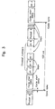
- Isochronous transmission of IEEE 1394 operates by transmitting isochronous packets, responding to a cycle sync every 125 ⁇ s as shown in Figure 3. Detailed specifications on the IEEE 1394 are described in the standard published in 1995.
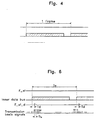
- Figure 4 shows the state of the inner bus 16 during transmission of one frame of data.
- the inner bus of the digital camcorder 10 usually has a high transfer rate at only specific parts in the frame.
- the number of source packets is 250 per frame and the number of cycle sync per frame is approximately 266.9.
- empty packets without data should be allocated to 16 or 17 isochronous cycles in order to transmit image information of a frame through the IEEE 1394 bus.
- the timing of the inner bus of the digital camcorder should be synchronized with the output timing through the IEEE 1394 bus.
- the empty packet insertion is to be determined to conform with [Definition 1, 2 ⁇ ].
- An aim of embodiments of the present invention is to provide transmission in accordance with definitions of the SD-format digital interface in communication devices with an isochronous communication mode like the digital data transmission and reception definitions of IEEE 1394.
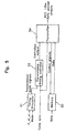
- FIG. 5 is a block diagram of a device for transmitting audio and/or video data according to an embodiment of the present invention. As shown in the drawing, there is provided: a timing simulator 51 for outputting transmission basis signals; a transmission timing controller 52 for generating controlled output for transmitting packets at every cycle sync; a memory 53 for temporarily storing data to be transmitted; and a transmitter 54 for receiving the data from the memory 53, and composing and transmitting packets according to the controlled output and the cycle sync.
- a timing simulator 51 for outputting transmission basis signals
- a transmission timing controller 52 for generating controlled output for transmitting packets at every cycle sync
- a memory 53 for temporarily storing data to be transmitted
- a transmitter 54 for receiving the data from the memory 53, and composing and transmitting packets according to the controlled output and the cycle sync.
- the timing simulator 51 receives a frame start delay signal F_st_d signal that is obtained by delaying a frame start signal F_st signal, corresponding to the beginning of the transmission of the first source packet in a frame of the inner bus of a camcorder, by a predetermined length of time.
- the timing simulator 51 also receives mode signals indicating whether the data is in NTSC mode or in PAL mode. The timing simulator 51 then outputs transmission basis signals according to the F_st_d signals and the mode signals.
- the transmission timing controller 52 receives the transmission basis signals and generates controlled output for transmitting packets at every cycle sync occurring every 125 ⁇ s, such that when a cycle sync occurs in a transmission basis signal interval, a packet with source packet data is transmitted at the cycle sync and when two cycle syncs occur in a transmission basis signal interval, a packet with source packet data is transmitted at only one of the two cycle syncs and an empty packet without data is transmitted at the other cycle sync.
- the timing simulator outputs transmission basis signals at every T ix interval according to the signal mode (NTSC mode or PAL mode).
- T ix represents a time fragment of a frame divided into 250 or 300 source packets.
- Td in Figure 6 shows a time delay for filling the memory 53 with transmission data to buffer the transmission data. Operators may determine the length of this delay, which may be used for buffering the data in a memory.
- the operator determines a length of time as the time delay that is consumed to store data in the memory 53 so that the transmitter of the present invention does not cause underflow during the transmission of the data.
- time delay is determined in accordance with the data transfer rate of the inner data bus of a digital system (e.g., camcorder) that is going to transmit the data.
- the consumed time (i.e., the time delay T d ) is the length of time taken to store one source packet in the memory 53.
- the present invention includes: an input device (not shown) for receiving the time delay T d from the outside; and a timing controller (not shown) for generating a frame start signal F_st signal, corresponding to the beginning of the transmission of the first source packet in a frame of the inner data bus, and generating a frame start delay signal F_st_d signal that is obtained by delaying the F_st signal by the time delay T d and inputting the F_st_d signal into the timing simulator 52.
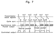
- Figure 7 is a timing chart of operation of the transmission timing controller 52 and the transmitter 54.
- a cycle of the transmission basis signal is 133.5 ⁇ s in 525-60 system (i.e., NTSC system) and is 133.3 ⁇ s in 625-60 system (i.e., PAL system).
- the cycle of the transmission basis signal is longer than the cycle of the cycle sync for the IEEE 1394, which is 125 ⁇ s.
- the transmission timing controller 52 generates controlled output signals which are set (i.e., shown as rising edges in Figure 7) responsive to transmission basis signals and are reset (i.e., shown as falling edges in Figure 7) responsive to cycle syncs.
- the transmitter 54 transmits packets at every cycle sync such that when the controlled output signal is in the reset state, an empty packet without data is transmitted through a communication wire (not shown) and when the controlled output signal is in the set state, a packet with data that is read from the memory 53 is transmitted through the communication wire (not shown).
- the cycle of transmission basis signal is longer than the cycle of the cycle sync. Therefore, one or two cycle syncs may occur in a transmission basis signal interval.
- an n th source packet is transmitted.
- an (n+2) th source packet is transmitted and at the second cycle sync (shown as (m+3) th cycle sync) after the transmission basis signal, an empty packet is transmitted.
- the data distribution can be controlled in a predetermined margin and provide a uniform data transfer rate defined with respect to SD-VCR DIF.
- a value of the frame start delay F_st_d inputted into the timing simulator 51 and a value for designating the mode of a color television transmit-receive mode may be predesignated in the timing simulator 51.
- the device and method for transmitting digital audio and/or video data is capable of making the different data transfer rates of the inner bus of the digital device (e.g., a camcorder) and IEEE 1394 bus corresponding to the data transfer rate defined with respect to SD-VCR DIF, thereby satisfying the specifications for an SD-format digital interface.
- the digital device e.g., a camcorder
- IEEE 1394 bus corresponding to the data transfer rate defined with respect to SD-VCR DIF
Landscapes
- Engineering & Computer Science (AREA)
- Signal Processing (AREA)
- Multimedia (AREA)
- Computer Networks & Wireless Communication (AREA)
- Small-Scale Networks (AREA)
- Communication Control (AREA)
- Data Exchanges In Wide-Area Networks (AREA)
- Time-Division Multiplex Systems (AREA)
Claims (16)
- Vorrichtung zum Übertragen digitaler Audio- und Videodaten, die entsprechend einer Übertragungsspezifikation in einem isochronen Übertragungsmodus einen Strom von Quellen-Paketen von einer ersten digitalen Vorrichtung zu einer zweiten digitalen Vorrichtung überträgt und die umfasst:gekennzeichnet durch:einen Speicher (53), der die Quellen-Pakete speichert;eine Übertragungszeit-Steuereinrichtung (51, 52), die einen Zeitpunkt zum Übertragen von Quellen-Paketen und leeren Paketen steuert, um den Übertragungs-Zeitablauf eines inneren Busses der ersten digitalen Vorrichtung in einen Zeitablauf umzuwandeln, der in der Übertragungsspezifikation vorbestimmt ist; undeine Übertragungseinrichtung (54), die die leeren Pakete von der Übertragungszeit-Steuereinrichtung (51, 52) gesteuert einfügt und überträgt, während die Quellen-Pakete, die in dem Speicher (53) gespeichert sind, Steuersignalen gemäß übertragen werden.
- Vorrichtung nach Anspruch 1, wobei die Übertragungszeit-Steuereinrichtung enthält:einen Zeitablauf-Simulator (51), der vorgegebene Signale und ein vorgegebenes Modus-Signal empfängt, um einen Strom der Quellen-Pakete zu übertragen, und Übertragungs-Basissignale entsprechend den vorgegebenen Signalen und dem Modus-Signal ausgibt; undeine Übertragungs-Zeitablaufsteuerung (52), die die Übertragungs-Basissignale und Zyklussynchronisierungs-Signale empfängt, die zu jedem vorgegebenen Zeitabschnitt erzeugt werden, und einen gesteuerten Ausgang zum Übertragen der Pakete gemäß vorbestimmter Regeln erzeugt.
- Verfahren zum Übertragen eines Stroms von Quellen-Paketen von einer ersten digitalen Vorrichtung zu einer zweiten digitalen Vorrichtung gemäß einer Übertragungs-Spezifikation in einem isochronen Übertragungsmodus, das die folgenden Schritte umfasst:wobei gemäß den vorgegebenen Definitionen, wenn eine Zyklus-Synchronisierung in einem Übertragungs-Basissignalintervall auftritt, ein Paket mit Quellen-Paketdaten, das in der Zyklus-Synchronisierung gültig ist, zu der Zyklus-Synchronisierung übertragen wird, und, wenn zwei Zyklus-Synchronisierung in einem Übertragungs-Basissignalintervall auftreten, ein Paket mit Quellen-Paketdaten zu lediglich einer der zwei Zyklus-Synchronisierung übertragen wird und ein leeres Paket ohne Daten zu der anderen Zyklus-Synchronisierung übertragen wird.Empfangen vorgegebener Zeitablaufsignale, die von dem Übertragungs-Zeitablauf eines inneren Busses der ersten digitalen Vorrichtung hergeleitet werden, und eines vorgegebenen Modus-Signals, um den Strom der Quellen-Pakete zu übertragen, und Ausgeben von Übertragungs-Basissignalen entsprechend den vorgegebenen Signalen und dem Modus-Signal; undEmpfangen der Übertragungs-Basissignale und von Zyklus-Synchronisierungen, die zu jedem vorgegebenen Zeitraum erzeugt werden, und Übertragen der Quellen-Pakete und leerer Pakete gemäß vorgegebener Regeln,
- Vorrichtung nach Anspruch 2 bzw. Verfahren nach Anspruch 3, wobei die vorgegebenen Zeitablauf-Signale nach einem vorgegebenen Zeitabschnitt nach der Erzeugung eines Signals erzeugt werden, das anzeigt, dass die Übertragung eines ersten Quellen-Paketes in einem Rahmen des inneren Busses der ersten digitalen Vorrichtung beginnt.
- Vorrichtung nach Anspruch 4 oder Verfahren nach Anspruch 4, wobei der vorgegebene Zeitabschnitt ein Zeitabschnitt ist, der erforderlich ist, um eines der Quellen-Pakete in dem Speicher zu speichern, d.h. ein Zeitabschnitt, der erforderlich ist, um die Quellen-Pakete in dem Speicher zu füllen, und so die Quellen-Pakete zu puffern.
- Vorrichtung nach Anspruch 4 oder 5, wobei die Übertragungszeit-Steuereinrichtung des Weiteren umfasst:eine Eingabeeinrichtung zum Eingeben des vorgegebenen Zeitabschnitts von außen, um den vorgegebenen Zeitabschnitt zu bestimmen; undeine Zeitablauf-Steuereinrichtung zum Erzeugen der vorgegebenen Zeitablauf-Signale nach dem vorgegebenen Zeitabschnitt.
- Verfahren nach Anspruch 5, wobei der vorgegebene Zeitabschnitt von einer Bedienungsperson bestimmt wird.
- Vorrichtung nach Anspruch 2 oder Verfahren nach Anspruch 3, wobei das vorgegebene Modus-Signal anzeigt, ob die Daten im NTSC-Modus vorliegen.
- Vorrichtung nach Anspruch 2 oder Verfahren nach Anspruch 3, wobei das vorgegebene Modus-Signal anzeigt, ob die Daten im PAL-Modus vorliegen.
- Vorrichtung nach Anspruch 2 oder Verfahren nach Anspruch 3, wobei der vorgegebene Zeitabschnitt 125 µs beträgt.
- Vorrichtung nach Anspruch 2, wobei der Zeitablauf-Simulator Übertragungs-Basissignale entsprechend den vorgegebenen Signalen und dem Modus-Signal ausgibt, um einen Strom der Quellen-Pakete zu übertragen, wobei die vorgegebenen Signale und das Modus-Signal vorbestimmte Signale und nicht neu eingegebene Signale sind.
- Vorrichtung nach Anspruch 2, wobei gemäß den vorgegebenen Regeln, wenn eine Zyklus-Synchronisierung in einem Übertragungs-Basissignalintenrall auftritt, ein Paket mit Quellen-Paketdaten, das in der Zyklus-Synchronisierung gültig ist, zu der Zyklus-Synchronisierung übertragen wird, und, wenn zwei, Zyklus-Synchronisierungen in einem Übertragungs-Basissignalintervail auftreten, ein Paket mit Quellen-Paketdaten zu lediglich einer der zwei Zyklus-Synchronisierungen übertragen wird und ein leeres Paket ohne Daten zu der anderen Zyklus-Synchronisierung übertragen wird.
- Vorrichtung nach Anspruch 12 oder Verfahren nach Anspruch 3, wobei das Übertragungsbasis-Signalintervall ein Zyklus-Intervall ist, das ein Zeitbruchteil eines Rahmens ist, der im NTSC-Modus in 250 unterteilt wird.
- Vorrichtung nach Anspruch 12 oder Verfahren nach Anspruch 3, wobei das Übertragungsbasis-Signalintervall ein Zyklus-Intervall ist, das ein Zeitbruchteil eines Rahmens ist, der im PAL-Modus in 300 unterteilt wird.
- Vorrichtung nach Anspruch 1 oder Verfahren nach Anspruch 3, wobei der Übertragungsstandard der Standard IEEE 1394 ist.
- Verfahren nach Anspruch 3, wobei der Schritt des Aüsgebens von Übertragungs-Basissignalen einen Schritt zum Ausgeben von Übertragungs-Basissignalen entsprechend den vorgegebenen Signalen und den Modus-Signalen zum Übertragen eines Stroms der Quellen-Pakete einschließt, und die vorgegebenen Signale sowie die Modus-Signale vorbestimmte Signale und nicht neu eingegebene Signale sind.
Applications Claiming Priority (2)
| Application Number | Priority Date | Filing Date | Title |
|---|---|---|---|
| KR9713864 | 1997-04-15 | ||
| KR1019970013864A KR100208012B1 (ko) | 1996-09-06 | 1997-04-15 | 디지털 오디오/비디오 데이터 전송 장치 및 방법 |
Publications (3)
| Publication Number | Publication Date |
|---|---|
| EP0873019A2 EP0873019A2 (de) | 1998-10-21 |
| EP0873019A3 EP0873019A3 (de) | 2001-04-04 |
| EP0873019B1 true EP0873019B1 (de) | 2004-05-12 |
Family
ID=19502846
Family Applications (1)
| Application Number | Title | Priority Date | Filing Date |
|---|---|---|---|
| EP97306194A Expired - Lifetime EP0873019B1 (de) | 1997-04-15 | 1997-08-14 | Vorrichtung und Verfahren zum Übertragen von digitalen Audio- und Videodaten |
Country Status (4)
| Country | Link |
|---|---|
| EP (1) | EP0873019B1 (de) |
| JP (1) | JP3034492B2 (de) |
| CN (1) | CN1136693C (de) |
| DE (1) | DE69729068T2 (de) |
Families Citing this family (10)
| Publication number | Priority date | Publication date | Assignee | Title |
|---|---|---|---|---|
| JP2000183904A (ja) * | 1998-12-16 | 2000-06-30 | Matsushita Electric Ind Co Ltd | パケット送出方法及びパケット送出装置 |
| US7492393B2 (en) * | 1999-02-12 | 2009-02-17 | Sony Corporation | Method of and apparatus for generating a precise frame rate in digital video transmission from a computer system to a digital video device |
| JP3424620B2 (ja) * | 1999-09-24 | 2003-07-07 | 日本電気株式会社 | アイソクロナスパケット転送方法,該転送用制御プログラムの記録媒体,ブリッジ及びパケット転送制御lsi |
| US6522649B1 (en) | 2000-04-07 | 2003-02-18 | Omneon Video Networks | Method of distributing video reference signals as isochronous network packets |
| US6895009B1 (en) | 2000-04-07 | 2005-05-17 | Omneon Video Networks | Method of generating timestamps for isochronous data |
| EP1223516A3 (de) * | 2000-10-31 | 2009-04-22 | Texas Instruments Incorporated | Verfahren und Vorrichtung zur Übertragung von komprimierten oder hochauflösenden Daten über eine isochrone Signalverbindung |
| FR2832827B1 (fr) * | 2001-11-23 | 2004-10-22 | Canon Kk | Procedes et dispositifs de gestion des transmissions de donnees isochrones sur des supports non dedies |
| US7949777B2 (en) | 2002-11-01 | 2011-05-24 | Avid Technology, Inc. | Communication protocol for controlling transfer of temporal data over a bus between devices in synchronization with a periodic reference signal |
| CN104679546B (zh) * | 2013-12-02 | 2018-11-09 | 联想(北京)有限公司 | 一种信息处理方法及电子设备 |
| CN108234104B (zh) * | 2016-12-12 | 2020-11-13 | 中国航空工业集团公司西安航空计算技术研究所 | 基于ieee1394-2008协议的等时周期资源管理方法 |
-
1997
- 1997-08-14 DE DE69729068T patent/DE69729068T2/de not_active Expired - Fee Related
- 1997-08-14 EP EP97306194A patent/EP0873019B1/de not_active Expired - Lifetime
- 1997-08-21 CN CNB971133875A patent/CN1136693C/zh not_active Expired - Fee Related
-
1998
- 1998-02-10 JP JP10028855A patent/JP3034492B2/ja not_active Expired - Fee Related
Also Published As
| Publication number | Publication date |
|---|---|
| JPH10303954A (ja) | 1998-11-13 |
| EP0873019A3 (de) | 2001-04-04 |
| DE69729068T2 (de) | 2004-09-16 |
| EP0873019A2 (de) | 1998-10-21 |
| CN1136693C (zh) | 2004-01-28 |
| DE69729068D1 (de) | 2004-06-17 |
| CN1196625A (zh) | 1998-10-21 |
| JP3034492B2 (ja) | 2000-04-17 |
Similar Documents
| Publication | Publication Date | Title |
|---|---|---|
| US6317440B1 (en) | Device and method for transmitting digital audio and video data | |
| US5781599A (en) | Packet receiving device | |
| JP4623524B2 (ja) | オーディオ/ビデオ/データをシステム・バスを介して転送する装置 | |
| US6055247A (en) | Data transmission method, data transmission apparatus and data transmission system | |
| KR100358398B1 (ko) | 패킷전송방식 | |
| US7055050B2 (en) | Network synchronization technique | |
| CN1151640A (zh) | 控制通信的方法和其电子设备 | |
| EP0873019B1 (de) | Vorrichtung und Verfahren zum Übertragen von digitalen Audio- und Videodaten | |
| US6026434A (en) | Data transmission processing system | |
| KR100457508B1 (ko) | 타임 스탬프 옵셋 설정 장치 및 그 방법 | |
| JP3546799B2 (ja) | データ送受信装置 | |
| JPH0955767A (ja) | データ伝送装置 | |
| JPH10313448A (ja) | 動画像送信装置および受信装置 | |
| JP3578156B2 (ja) | パケット受信装置 | |
| JP2002084288A (ja) | 信号処理回路および信号処理方法 |
Legal Events
| Date | Code | Title | Description |
|---|---|---|---|
| PUAI | Public reference made under article 153(3) epc to a published international application that has entered the european phase |
Free format text: ORIGINAL CODE: 0009012 |
|
| 17P | Request for examination filed |
Effective date: 19970822 |
|
| AK | Designated contracting states |
Kind code of ref document: A2 Designated state(s): DE FR GB |
|
| PUAL | Search report despatched |
Free format text: ORIGINAL CODE: 0009013 |
|
| AK | Designated contracting states |
Kind code of ref document: A3 Designated state(s): AT BE CH DE DK ES FI FR GB GR IE IT LI LU MC NL PT SE |
|
| RIC1 | Information provided on ipc code assigned before grant |
Free format text: 7H 04N 7/52 A, 7H 04N 7/06 B, 7G 06F 13/42 B, 7H 04N 7/24 B |
|
| AKX | Designation fees paid |
Free format text: DE FR GB |
|
| 17Q | First examination report despatched |
Effective date: 20030424 |
|
| GRAP | Despatch of communication of intention to grant a patent |
Free format text: ORIGINAL CODE: EPIDOSNIGR1 |
|
| GRAS | Grant fee paid |
Free format text: ORIGINAL CODE: EPIDOSNIGR3 |
|
| GRAA | (expected) grant |
Free format text: ORIGINAL CODE: 0009210 |
|
| AK | Designated contracting states |
Kind code of ref document: B1 Designated state(s): DE FR GB |
|
| REG | Reference to a national code |
Ref country code: GB Ref legal event code: FG4D |
|
| REF | Corresponds to: |
Ref document number: 69729068 Country of ref document: DE Date of ref document: 20040617 Kind code of ref document: P |
|
| ET | Fr: translation filed | ||
| PLBE | No opposition filed within time limit |
Free format text: ORIGINAL CODE: 0009261 |
|
| STAA | Information on the status of an ep patent application or granted ep patent |
Free format text: STATUS: NO OPPOSITION FILED WITHIN TIME LIMIT |
|
| 26N | No opposition filed |
Effective date: 20050215 |
|
| PGFP | Annual fee paid to national office [announced via postgrant information from national office to epo] |
Ref country code: DE Payment date: 20080829 Year of fee payment: 12 |
|
| PGFP | Annual fee paid to national office [announced via postgrant information from national office to epo] |
Ref country code: FR Payment date: 20080818 Year of fee payment: 12 |
|
| PGFP | Annual fee paid to national office [announced via postgrant information from national office to epo] |
Ref country code: GB Payment date: 20080827 Year of fee payment: 12 |
|
| GBPC | Gb: european patent ceased through non-payment of renewal fee |
Effective date: 20090814 |
|
| REG | Reference to a national code |
Ref country code: FR Ref legal event code: ST Effective date: 20100430 |
|
| PG25 | Lapsed in a contracting state [announced via postgrant information from national office to epo] |
Ref country code: FR Free format text: LAPSE BECAUSE OF NON-PAYMENT OF DUE FEES Effective date: 20090831 Ref country code: DE Free format text: LAPSE BECAUSE OF NON-PAYMENT OF DUE FEES Effective date: 20100302 |
|
| PG25 | Lapsed in a contracting state [announced via postgrant information from national office to epo] |
Ref country code: GB Free format text: LAPSE BECAUSE OF NON-PAYMENT OF DUE FEES Effective date: 20090814 |