EP0873262B1 - Transportvorrichtung für stückgut - Google Patents
Transportvorrichtung für stückgut Download PDFInfo
- Publication number
- EP0873262B1 EP0873262B1 EP96945161A EP96945161A EP0873262B1 EP 0873262 B1 EP0873262 B1 EP 0873262B1 EP 96945161 A EP96945161 A EP 96945161A EP 96945161 A EP96945161 A EP 96945161A EP 0873262 B1 EP0873262 B1 EP 0873262B1
- Authority
- EP
- European Patent Office
- Prior art keywords
- transport apparatus
- bars
- loading
- guide
- bar
- Prior art date
- Legal status (The legal status is an assumption and is not a legal conclusion. Google has not performed a legal analysis and makes no representation as to the accuracy of the status listed.)
- Expired - Lifetime
Links
- 239000000463 material Substances 0.000 claims abstract description 54
- 239000013536 elastomeric material Substances 0.000 claims description 8
- 238000003860 storage Methods 0.000 description 35
- 239000002184 metal Substances 0.000 description 7
- 238000000034 method Methods 0.000 description 4
- 239000004744 fabric Substances 0.000 description 3
- 238000003780 insertion Methods 0.000 description 3
- 230000037431 insertion Effects 0.000 description 3
- 238000004519 manufacturing process Methods 0.000 description 3
- 238000013461 design Methods 0.000 description 2
- 239000013013 elastic material Substances 0.000 description 2
- 239000011888 foil Substances 0.000 description 2
- 239000011521 glass Substances 0.000 description 2
- 238000003825 pressing Methods 0.000 description 2
- 238000012545 processing Methods 0.000 description 2
- 238000006748 scratching Methods 0.000 description 2
- 230000002393 scratching effect Effects 0.000 description 2
- 239000007787 solid Substances 0.000 description 2
- 239000000725 suspension Substances 0.000 description 2
- JXYWFNAQESKDNC-BTJKTKAUSA-N (z)-4-hydroxy-4-oxobut-2-enoate;2-[(4-methoxyphenyl)methyl-pyridin-2-ylamino]ethyl-dimethylazanium Chemical compound OC(=O)\C=C/C(O)=O.C1=CC(OC)=CC=C1CN(CCN(C)C)C1=CC=CC=N1 JXYWFNAQESKDNC-BTJKTKAUSA-N 0.000 description 1
- 208000033999 Device damage Diseases 0.000 description 1
- 238000013459 approach Methods 0.000 description 1
- 230000015572 biosynthetic process Effects 0.000 description 1
- 239000000872 buffer Substances 0.000 description 1
- 230000000295 complement effect Effects 0.000 description 1
- 230000006835 compression Effects 0.000 description 1
- 238000007906 compression Methods 0.000 description 1
- 238000001514 detection method Methods 0.000 description 1
- 230000005484 gravity Effects 0.000 description 1
- 230000001771 impaired effect Effects 0.000 description 1
- 238000009434 installation Methods 0.000 description 1
- 239000005022 packaging material Substances 0.000 description 1
- 238000004806 packaging method and process Methods 0.000 description 1
- 239000002985 plastic film Substances 0.000 description 1
- 238000002360 preparation method Methods 0.000 description 1
- 238000005096 rolling process Methods 0.000 description 1
- 238000007665 sagging Methods 0.000 description 1
- 230000035939 shock Effects 0.000 description 1
- 125000006850 spacer group Chemical group 0.000 description 1
- 238000012549 training Methods 0.000 description 1
Images




Classifications
-
- B—PERFORMING OPERATIONS; TRANSPORTING
- B65—CONVEYING; PACKING; STORING; HANDLING THIN OR FILAMENTARY MATERIAL
- B65D—CONTAINERS FOR STORAGE OR TRANSPORT OF ARTICLES OR MATERIALS, e.g. BAGS, BARRELS, BOTTLES, BOXES, CANS, CARTONS, CRATES, DRUMS, JARS, TANKS, HOPPERS, FORWARDING CONTAINERS; ACCESSORIES, CLOSURES, OR FITTINGS THEREFOR; PACKAGING ELEMENTS; PACKAGES
- B65D19/00—Pallets or like platforms, with or without side walls, for supporting loads to be lifted or lowered
- B65D19/38—Details or accessories
- B65D19/44—Elements or devices for locating articles on platforms
Definitions
- the present invention relates to a transport device for piece goods, consisting of a Frame with an upper guide for at least one held and guided on this guide first rod and with further rods, which are also on the upper guide or on one parallel guide at a distance below the upper guide substantially parallel to this extend the first rod, the rods carrying a web material which is between the rods held in the guides form loops as receiving pockets for general cargo.
- the term “Frame” is very broad and all types of open and closed frames or Frame includes, including closed boxes or boxes made only from side walls and Floor and / or ceiling exist.
- the terms “frame” and “container” are therefore used in the present application largely used synonymously.
- the concept of "Web material” is very broad and includes foils as well as fabrics, nets and individual, strips of foil or fabric material or cords arranged side by side in parallel. The web material is suspended from two adjacent poles and hangs between these two rods in the form of a loop to form a receiving pocket downwards by. These pockets or loops can be open or closed at the front, e.g.
- the web material can optionally only be between two adjacent bars extend so that two rods with the pocket in between regardless of the other pockets, but preferably the web extends over more than two Rods so that a series of connected loops or pockets is formed.
- Such transport devices are primarily intended for the transport of piece goods, in particular for the transport of the same piece goods as finished parts or as Components or semi-finished parts required for the production and assembly of more complex objects become.
- An example of this are body parts in the automotive industry, which, for. B. in one of the body assembly factory for the cars, which is further away, stamped and shaped and only then have to be transported to the installation site.
- Many general cargo are sensitive to scratching, bumps or blows, as this either destroys can be damaged or deformed or at least become unsightly. they are then possibly useless for the further processing or manufacturing process.
- the loading and unloading process can be simplified and accelerated as much as possible. Specifically, it should If possible, not every single part in its own container with the appropriate cushioning material packed and the container can also be closed afterwards because the packaging in such containers and the subsequent removal is extremely time consuming and Production process is considerably more expensive, which is why it can also be quite expensive Packaging material contributes. In this respect, devices that are more or less preferred can be reused completely and unchanged.
- the known device already fulfills essential requirements with regard to fast loading and unloading and also with regard to reusability, in Usually without consumables.
- the object of the present invention is therefore in relation to this prior art to create a transport device with the features mentioned above, which protects the objects to be transported even better against damage without the fast loading and unloading and reusability are impaired.
- At least one support rod is provided, which below the upper guide parallel to the other rods and in the direction of the receiving bags or the piece goods held in them and in attachment the last of these pockets or the object accommodated therein can be moved and can be fixed in this position.
- the piece goods in the bags have that different forms, but preferably the transport device in the way is used that a number of identical objects in a frame or container is accommodated in the individual pockets arranged one behind the other.
- the transport device in the way is used that a number of identical objects in a frame or container is accommodated in the individual pockets arranged one behind the other.
- this includes does not mean that e.g. also different things in the pockets can be arranged that complement each other in shape, so that the device saves space is used or that one and the same objects alternately in different Orientation can be loaded into the pockets.
- the pockets suspended in the containers or frames form with the pockets located therein Total objects a vibrating structure and the individual pockets can easily vibrate in groups or against each other, so that either Knock up adjacent pockets or the pockets against the frame or Container walls or against adjacent containers or the objects contained therein attacks. This can cause undesirable damage to the individual pockets recorded objects come.
- the ability of the individual pockets to vibrate is increased by the additional Handrail, which is below the top guide and aligned parallel to the rest Poles in the direction of the last of the pockets or the object accommodated therein displaceable and attachable to it in plant, significantly reduced. If you e.g. introduces a series of 10 - 20 individual pockets, which are looped by a corresponding one Row of parallel rods of depending web material are formed and in to e.g. each the radiator hood of an automobile is included, so these, in suspended from a container or frame, swing bags relatively strongly.
- the pockets can also be damaged by very short loops are formed, in which only a lower part of the respective object is included. Only the first such pocket extends with one side to an upper guide or one Rod that is guided in such a guide and the following rods are essential arranged lower and form only very short loops or pockets, from which can be the individual objects extend upwards.
- the handrail after Load the bags with the individual items not on the bag, but on the last object pushed so that the objects themselves compressed and in the compressed position are largely fixed, so that a swing or Rocking is hardly possible anymore.
- a swing or Rocking is hardly possible anymore.
- An embodiment of the invention is preferred in which the upper and, if appropriate, the existing lower guide each consisting of a pair of laterally attached in the frame Guide rails exist. This gives the rods which are then opposite with their two Ends are guided on or in these guide rails, maximum stability for carrying the bags.
- the frame or container on one side of which is loaded or loaded and unloaded with the relevant objects from it has a closure flap.
- a flap can of course also provided on the two opposite sides of a container or frame be, so that optionally the unloading and loading of one as well as of the other Side can be done.
- a further handrail could also be provided be from the opposite side to the pockets or the pockets Objects can be pushed.
- a device is preferred to protect the objects accommodated in the pockets, in which the frame with side walls and / or floor and / or ceiling as one essentially closed container is formed.
- a container can be produced that corresponding walls, floor and ceiling on a supporting frame be attached, or the walls of the container can also be self-supporting, so that the "frame" is formed by the walls and possibly the floor and ceiling itself.
- Corresponding guide rails are then e.g. attached directly to the walls of the container. Conversely, the guide rails could also lead to an open frame or frame be connected to each other and then appropriate walls could be on this frame be attached.
- an embodiment of the invention is preferred in which holding parts and stop parts for holding or stopping the rods in the guides in a loading or unloading position of the respective rods are provided.
- This configuration is specifically about the Items individually and one after the other are taken out of the pockets or into the pockets be used.
- the respective bag should be in a loading or unloading position accessible and also fixed in this position, including the holding and stopping parts mentioned serve.
- the rod of the next pocket can already be in a preparation position held or stopped.
- An expedient embodiment of the present invention results from the fact that the Handrail is provided on a sliding carriage that can be moved into the frame.
- This The loading sled fulfills a double function, by both aligning the Securing the handrail to the last bag or last object at the same time but also serves as an auxiliary device that facilitates the loading and unloading of the device and accelerates.
- this loading carriage is in the frame or container slidably and can accordingly at least a bit out of the frame be pulled out.
- the extended position is the unloading or loading position and in the retracted position is the handrail attached to the loading carriage Bags or objects pressed, it being understood that the carriage in different inserted positions in the frame can be fixed, so that the position of the Handrail can be varied accordingly to ensure a secure attachment to the last pocket or to get the last item.
- the loading sled has a one arranged behind the holding rod Charging bar on, and is also conveniently under the grab bar and the charging bar a stowage box for holding rods and the attached sheet material (of empty pockets).
- the loading carriage is therefore specifically designed so that the Handrail and the loading bar somewhere on a medium level of the frame or Container are located below the upper guides, so that there is still space for one Storage box is.
- the handrail is on the the objects or bags in the Container facing side arranged and the loading bar is behind, i.e. on the side facing away from the pockets. With the slide pulled out, e.g. the handrail either be already out of frame or roughly at the level of The front edge of the container or frame.
- the rod in question is removed from the end of the guide and placed over the sled down into the (open front) storage box. It lies down the web, which forms one side of the bag or loop, first over the handrail and then over the charging bar, and the bag is largely open, being on one side the bag only a short lower section of the bag between the handrail and the lowest point of the pocket is formed. The item is then easily accessible and can be taken out of the pocket.
- the first rod is preferably in one Storage box inserted existing guide and pulls at least a piece of it fastened web material into the storage box.
- the rest of the web material this The bag can either be pushed into the storage box by hand or simply remain above the handrail and loading bar. Then the next one Bar in the same way over the loading carriage, i.e. over the handrail and the loading bar moved away and placed or pushed into the storage box. That is the next Bag open and the item can be removed. In this way, gradually after removing all the bars from the top guide and in the storage box stowed, with at least part of the web material being accommodated in the storage box and the remaining web material may lie loosely on the support bar and loading bar.
- the carriage can then be placed in the frame or Container pushed back and fixed and in this form is the container or the Frame immediately ready, new items again, starting with the first bag, to record.
- the first or last bar depending on whether you are loading or unloading viewed, can remain in the upper guide.
- a for loading appropriate item inserted in the first, already open pocket and the individual Bars are then removed in reverse order from the storage box and into the upper guide hooked in, whereby the individual pockets are automatically completed and getting closed.
- the storage box expediently has one at its lower end and under the loading bar hinged and swiveling storage flap. This can easily be moved forward be pivoted or opened and thus defines a receiving opening for the individual Poles.
- the storage flap can also be tilted in the manner of a chute, so that one can simply let the individual rods fall into the stowage flap from above, on which then slide them into the storage box.
- the loading carriage should be a unit in the Frame can be moved into it and then in a variable position in the frame be fixable.
- the handrail on the loading carriage be slidable and variably fixable if the loading carriage in the frame only one has fixed or only roughly graded fixable positions.
- the loading bar and the holding bar are in the preferred embodiment by side connecting links connected to each other so that the handrail serves as an axis Loading bar swiveled around and can be folded down.
- the upper guides or guide rails should be used to transport relatively heavy objects run cranked downward at its end facing the loading side. So that will a course described, in which the upper guides or guide rails at an angle kinked below and at a last end section again parallel to the rest of the Guides or run slightly inclined upwards. These end sections of the guides are then lower than the actual part of the upper guide and it is e.g. possible, after a heavy object is placed in a pocket, the rod closing this pocket first into the lower end section of the guide or the guide rails, with the lower end of the pocket forming Loops may still be sitting on the floor or on the loading sled and the weight the object contained in the bag supports.
- the rod on the sloping section of the guide rails are pushed up, including the Bag or the lower end portion of the bag is raised accordingly. Needed for this less force than for directly hanging the rods at the higher level of the Main part of the upper guide rails. If necessary, you have to make sure that the bottom part of the objects slips relatively easily in the pocket. Subsequently the bag hangs freely on the two poles which are in the main part of the upper guide to run.
- all the bars carrying the web material possibly also the Handrail and also the loading carriage on their opposite ends or sides rollers on which are guided in the corresponding guides or guide rails, specifically in such a way that the rollers cannot slip out of the side of the guides.
- the device expediently has one mounted in the frame own guide for the handrail on the mentioned middle level.
- the individual bags are loaded and unloaded or held in them and upward protruding objects are relatively easily accessible, so that one is Loading sled not required, but a storage space for the bars and the web material of the Bags if these are pulled out one after the other from their corresponding guides in order to empty the pockets one after the other.
- a corresponding receiving device for such rods and the web material or is provided in the transport device.
- the receiving device is attached from the side with a free space Guide rails are formed to accommodate the rod end, the container and the guides or the web material lengths are chosen so that this space below the pockets remains in the container or frame.
- this brake fixing device consists of one attached to a shaft elongated plate or a strip of an elastomeric material, preferably made of Rubber, the shaft preferably being perpendicular to the rods and approximately parallel to the Extends guides for the rods and is pivotable about its longitudinal axis that thereby the plate or strip of elastomeric material with one of its longitudinal edges the rods can be brought into engagement, this plate or its longitudinal edge being in contact deformed accordingly on the individual rods.
- the shaft can have a largely arbitrary cross section and is at its ends rotatably mounted and preferably connected to a corresponding lever that prevents rotation the shaft is also allowed against the resistance that may occur.
- a layer is made of a brake material, being the brake material
- a brake material being the brake material
- an elastomeric material is preferred attached to a rail attached to a series of swivel links on a plane containing the rail itself is.
- the pivot plane is a vertical plane and the rail is above that Arranged bars and is pressed into position by one or more springs pulled, in which the brake layer is lifted off the rods.
- a corresponding braking or fixing device is preferred according to the invention designed so that it with a locking mechanism of the loading carriage or the closure flap or the insertion mechanism of the handrail is coupled such that it is at inserted loading carriage, inserted holding rod or closed locking clip is forcibly engaged with the rods.
- the device can do so in detail be designed so that the closing or insertion process automatically Brake device is actuated, or the braking or fixing device can be designed in this way be that they move the handrail and loading carriage to the desired position and / or prevents the closure flap from closing as long as the braking device is not has been engaged with the rods.
- a braking device can also be provided specifically for the handrails, in which If several handrails are used, this braking device when pushing one another handrail automatically or z. B. should be releasable by foot pedal actuation, so rods that have already been pushed in together with the continued loading of the device move the already loaded objects further into the container or frame can.
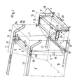
- FIG. 1 shows a front section of a frame 1 with a loading carriage 15.
- the walls 9, 9 'and the bottom 10 of the frame are shown broken off as well the upper guide rails 11 and 11 'for the rods 2 and 3.
- the here designed as a container Frame 1 can therefore move significantly further in the direction of the left side in FIG. 1 extend.
- the container 1 and other parts are also drawn transparently to better see details.
- the first rod 2 of the first pocket 5 closes any other rods 3 and the web material is preferably continuous or extends between two adjacent rods, so that you have a total continuous row or chain of such pockets 5 receives.
- the second bag 5 that itself to the rod 3 accommodated in the guide 11, 11 ' is in the open state in FIG State shown.
- an unloading carriage 15 is provided around the bags, in which piece goods, e.g. Body parts, Glass plates or other objects can be arranged, easy to empty and also easy To be able to load.
- a rod 3 is a Pocket 5 from the guide 11 or 11 'over the obliquely extending offset portion 11a and the horizontal end portion 11 b completely removed from the guide, the End section 11b still has a stop 11c projecting from below, which slips out or falling out of the rod 3 prevented. About this stop or paragraph 11c must the corresponding roller 30 are lifted away.
- the cross section of the loading carriage is approximately a trapezoidal shape, the upper side of the loading carriage being defined by that of the container facing handrail 7 and the loading bar facing away from the container 16. Under handrail 7 and the loading bar 16, the loading carriage 15 has a free space which serves as storage space for bars 3 and web material 4 is used.
- the loading carriage has on its front side on the right in FIG.
- 1 15 also has a storage flap 18, which has the shape of a pouring or baffle plate has and from a sheet metal plate extending across the loading carriage 15 and two There are side plates, which have approximately the shape of a circular sector and open the Allow stowage flap 18 through an angle between typically 30 ° and 60 °.
- the rod 3 is then removed from section 11b of the guide rails 11, 11 'removed and placed in the storage box 17 immediately in front of the storage flap.
- the web material 4 is placed on one side of the pocket 5 over the support rod 7 and the loading bar 16 away and extends to the bar just put down 3. Die Length sections L1, L2 and L3 of the web material between the lowest point of the pocket 5 and the rod 3 correspond to the total length L that can still be seen on the left Pocket side.
- the loading carriage 15 can also have an additional crossbar in its lower area have, which rests on the outside of the lower edge of a pocket 5 when it is opened or in open state.
- Optional lateral guide rails are not shown in FIG. 1 in the storage box into which the individual rods 3 are pushed can. Such guide rails can be arranged one above the other in several floors, to fully utilize the volume of the storage box.
- next bag is emptied in a completely analogous manner, i.e. it will be the the next rod 3 is removed via the sections 11a, 11b from the guide rails 11, 11 'and via holding rod 7 and loading rod 16, if necessary also via the web material lying thereon earlier bags, filed and the rod 3 is then in turn as far as possible in the Storage box pushed in.
- This is done in succession with all the rods 3, one corresponding transport device typically about twenty such rods 3 and Pockets 5 has.
- the last rod 2 can remain in the container 1.
- the pockets 5 can have end-side fastener tapes 46, e.g. with Velcro on the front edges of the pockets 5 on the web material 4 can be attached.
- stop parts 14 are articulated at their rear end and have at their front end one with the rods 3 or the corresponding hand strap of the bag in Interrupting stop plate.
- the stop parts 14 are raised so that the rod 3 under the stop parts away to the sections 11a and 11b of the guide rails 11, 11 'can be moved. You can also do it at the same time the holding parts 13 are raised so that the next following rod 3 moves on can be and then held by the stop members 14 in the unloading or loading position.
- the individual pockets 5 are opened one after the other and the pockets therein Objects that are not shown in FIG. 1 can be made one after the other can be removed from the individual pockets 5.
- the storage box 17 with the rods 3 and the intermediate sheet material 4 or at least parts of the Web material filled.
- the storage box that with lateral rollers 30 in lower guide rails 27, 27 ' is guided back into the container 1 pushed in, a resiliently biased locking cam 28 with the help of a foot pedal 47 is raised and after insertion into the container 1 in one of the locking points 29 Bottom 10 of the container 1 latched.
- the container 1 can then be moved to another location be transported in order to again hold objects in the corresponding pockets then be transported back to their destination.
- the process described above takes place in the reverse order.
- the latching cam 28 is released from the latching webs 29 and the carriage 15 is moved out of the container 1 approximately so far that the front Holding rod 7 is approximately in the plane of the front of the container 1, as in Figure 1 is shown.
- the last rod 2 when unloading the transport device which is now the is the first rod of the first pocket 5, can either still in the shown in Figure 1 Position in the holding parts 13 or on the stop parts 14, but they could optionally also be stowed in the storage box 17.
- the stowage flap 18 opens when it is pulled out of the carriage 15 automatically, as will be described later.
- the stop parts 14 expediently have stops which pivot their movement limit up and down, whereby of course the swivel movement is sufficient to to let the rods 2, 3 pass.
- the first pocket is open because the web material 4 hangs down from the rod 2 and, if this web material in the storage box 17th is stowed, it is optionally pulled out and placed over the support rod 7, so that it hangs down to form the first open pocket similar to sections L and L1 of FIG open pocket of Figure 1.
- the object in question e.g. a Sheet metal plate or a body part, are placed in the pocket 5.
- the stowage flap 18 has a lever angled forward at its lower end Roll up at its free end. These serve to hold the damper when retracting the Slides in the frame 1 to close automatically because then the role of this lever with the bottom edge of the frame or container engages, thereby being raised and around the Swivel axis of the stowage flap pivoted, the stowage flap connected to the lever 18 is also pivoted and thus closed. Conversely, the storage flap opens due to the gravity and the relative arrangement of the damper 18 to your pivot axis automatically when the carriage is moved out of the container 1 and thereby the role of Lever slides down over the lower edge of the container.
- the holding parts 13 and stop parts 14 are shown again in more detail. Moreover can be seen next to the rollers 30, in a cross-sectionally curved guide rail 11 run and are secured against slipping out of the guide rail 11, also outside the rails and next to these arranged spacers or buffers 51 have a slightly larger diameter than the rollers 30 and so a contact of adjacent Prevent rolling. As you can see, the two adjacent stop parts 14, of which here however only one is shown, connected by a cross bar 45 so that it with a simple handle by lifting the cross bar 45, both at the same time Lift stop parts 14.
- the holding parts 13 are when moving the rod 3 to the rear automatically raised because the next following rod 3 on the lower inclined surface of the Holding parts 13 slides and lifts them.
- the stop parts are also raised automatically when the rods are inserted into the device, but must be when the device is unloaded on the cross bar 45 are raised to the rod 3 forward from the guide rails 11 to be able to pull out.
- the stop parts can also be used the holding parts 13 are coupled in order to actively lift the stop parts 14 also by to release the holding parts 13 held rod, possibly with a small delay compared to the stop parts 14.
- the holding parts 13 have at their free end Inclined surface 13a and in the locking recess an inclined surface inclined in the same direction 13b. These inclined surfaces allow the rods 3, 2 to be unloaded from behind can glide through under the holding parts 13; without this through external intervention must be raised, however, the rods are at the stop parts 14 at the latest further outward movement prevented.
- the bars 3 can do this when loading Stop part 14 happen, however, are held in the locking recess of the holding parts 13 and on a further inward movement prevented until the next rod 3 the inclined surface 13c detected, and thereby releases the rod 3 held in the locking recess, to then to take their place themselves.
- the carriage 15 pushed back into container 1.
- the handrail 7 comes with the last one loaded bag in contact, whereby it does not bother if e.g. with a not fully loaded Place a few more layers of web material 4 on the support rod 7.
- the loading carriage at the locking points 29 in different positions in Longitudinal direction of the container 1 are locked, the locking points here only schematically five points are indicated, but more or less over the entire length of the Can extend container 1.
- the support rod 7 upwards over the loading rod 16th be pivoted back down into the position shown in dashed lines in Figure 1. in this position, the charging rod 16 takes over the function of the holding rod 7 and is at Retracting the carriage 15 with the last pockets brought into contact or holding engagement.
- the individual support rods 2, 3 of the pockets 5 are preferably also used a corresponding braking device 20 fixed.
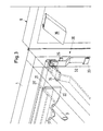
- FIG. 3 An exemplary embodiment of this is shown in FIG. 3 shown.
- the braking device 20 which consists of a shaft 21, one with the metal plate 21 'connected to the shaft 21 and a rubber plate fixed to the metal plate 21' or a rubber strip 22.
- the shaft 21 can by means of a lever 32 by 90 ° be rotated back and forth around its longitudinal axis.
- a position is shown in dashed lines of the lever 32 and the rubber plate 22 attached to the shaft, in which the braking device 20 is out of engagement with the rods 3.
- the fixation position is shown with solid lines.
- the brake lever 32 can in the released position of the braking device 20 behind one Hooks 34 are hooked onto an upper, transverse frame part of the frame 1 is attached. If the brake ends in the fixing position, as with a solid Lines are drawn, the brake lever 32 is held behind a hook 33, the a vertical spar of the frame 1 is attached.
- the shaft 21 with the fastened parts pivoted by 90 ° from the position shown in dashed lines, the edge of the rubber strip or the rubber plate 22 engages with the rods 3 and due to Its elasticity bends and curves around the individual rods 3. Hereby the individual rods 3 are securely held in position.
- the rubber strip or the rubber plate 22 another, preferably elastomeric Use material, such a strip also having recesses at predetermined intervals may have for receiving the rods 3 or have a continuous wave pattern can, the rods 3 then engaging such a strip with the rods slide into the corresponding recesses or depressions of the wave pattern.
- the Variant with a continuous straight rubber strip 22 has the advantage that the The distances between the individual rods cannot be determined and all rods in the The position they are in after they are fully loaded.
- FIG 3 a closure of the Prevent container 1 with the help of the hinged flap 8 as long as not Braking device is in the marked fixing position.
- the braking device is released and the brake lever is in the dashed position is located behind the hook 34.
- the Brake lever 32 has a forward projecting cam 35 and on the inside of the closure flap 8, a cam plate 36 is additionally attached.
- the cam 35 is forcibly engaged with the cam plate 36 and prevents the complete Closing the flap 8.
- FIG. 4 Another variant of a braking device is shown in FIG. 4.
- FIG. 4 is a plate 23 made of a rubber-elastic or elastomeric material, which has 3 good braking properties for the individual rods, on the underside of one rocking suspended rail 24 attached.
- the rail 24 has a U-shaped cross section and is via links 25 which e.g. the shape of individual bars or even crosswise can have sheet metal plates extending over the rail, suspended from an upper rail 24 ', which in turn is attached to the frame 1, preferably on a cover plate.
- connecting links 25 can consist of individual longitudinal and transverse bars or strive to exist, but they can also be sheet metal plates on their upper and lower Are flanged end and thereby one each bent across the U-shaped Legs extending vibrating rod 37 and 38 comprise.
- a spring can be connected to adjacent connecting members 25 in the manner shown in FIG 26 be attached, the upper cross bar 37 of a connecting link 25 to the lower Crossbar 38 connects the adjacent link 25 and which is dimensioned so that due to their spring tension, the lower rail 24 with the brake plate attached to it 23 in the solid position.
- the front end of the rail 24 is again provided with a pressure roller 39, which is in the solid position protrudes beyond the level of the front edge of the frame or the container 1.
- Figure 5 shows further measures to prevent transport damage to the in the Bags 5 transported items.
- the container or frame 1 is at the top left shown without internals such as guide rails and suspended pockets etc.
- the rear wall of the container 1 is attached in a corrugated form strips 40 made of a cushioning material, which, when a handrail approaches the last filled pocket, the first pocket 5 catch in this row of pockets in one end position and thus a softly padded one Form abutments.
- the bulges due to the waveform of the cushion material 40 can give way in the direction of the rear wall.
- the pockets themselves are also provided with corresponding ones Provide cushioning strips 41, which are preferably arranged at critical points where possibly sharp-edged sections of the objects 6 the inner wall of the pockets 5 touch. Because with such transport devices often large numbers of identical objects to be transported, it is often appropriate, especially to the transported Items 6 matched and adapted bags 5 to use, then can have corresponding cushioning material 41 at very specific points. Of course it is also possible to use upholstery elements or upholstery strips evenly on the outside and / or Distribute the inner surface of the individual bag, although care must be taken that these upholsteries do not take up too much volume because then the stowing of the Web material 4 is much more complex and difficult. It can also be seen in FIG.
- the pocket 5 still clearly the hanging loops 42 formed at the top of the bag which the rods 2 and 3 extend. It is understood that the pocket 5, starting from each of the two loops 42 can be continued as desired with further subsequent ones Bags 5.
- the top ends of the web material could be the individual pockets inserted into a holding profile and clamped therein, the holding profile can be an attached to the rods 2, 3 additional part or the rods themselves as corresponding profile parts are formed.
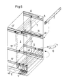
- FIG. 6 shows a further embodiment of the invention, in which the individual Pockets 5 'are only very small in comparison to the objects 6 contained therein Have height.
- the first rod 2 runs in an upper guide and forms one wall of a substantially extending over the entire height of the transport device Bag made of the web material 4.
- the next following bars 3 are much deeper lying guide rails 12, 12 ', so that the second wall of the first pocket and the following pockets 5 'are all significantly lower or shorter.
- a holding rod 7 is provided which is guided in a guide rail 19, 19 'at a medium level.
- This Support rod 7 can be covered with a cushioning material and is in the guide 19, 19 ' pressed the object 6.
- the support rods 7 have approximately the same Diameter like the lower bars 3 with the surrounding loops 42.
- the object 6 is then inserted into such a pocket and against the rear Wall of the first pocket or in the case of the later pockets against the previously in the guides 19, 19 'inserted holding rod 7 pivoted.
- the objects preferably plate-shaped objects 6, at a distance from the individual rods 3 held and in the middle area, support rods 7 set the desired distance between the objects 6 forth so that they can not touch and damage each other.
- a new support rod 7 is again inserted into the guides 19, 19 ' introduced.
- the holding rods 7 are in turn in an upper guideway 43, 43 'in stock held as long as they are not needed in the middle guide rails 19, 19 '.
- This Upper guideway 43, 43 ' is inclined slightly forward, so that the individual support rods 7 with a vertically aligned container 1 to the front against a stop, not shown here roll so that they can be easily removed from the front of the container 1.
- a holding rod 7 is received behind one in one of the pockets 5 'and object 6 extending upwards is inserted into the guides 19, 19 '.
- FIG. 7 also shows one that is also shown more generally in FIG. 6 Braking and fixing device 20 'shown, which is specially adapted to this variant.
- a braking and fixing device is provided the with the rocking suspension device shown in Figure 4, swinging suspended has certain things in common.
- the braking device 20 'shown in FIG. 7 is an upper rail 44 'rigid on the container, e.g. attached to the side container wall 9, and a lower rail 44 is parallel to the upper rail 44 'and via links 25' pendulum suspended.
- the elastic Restoring forces of the entire system then have a tendency to the individual rods with the objects to push back a bit, but keeping the top of the rods touches the lower edge of the rubber strip 22 'and takes it back a little.
- the rail 44 with the rubber strip 22 ' is forced to lower and comes so in ever stronger contact with the rods 7, so that the strip 22 'on its lower Edge bulges somewhat elastically and finally, when the rail 44 abuts the stop 49, holds all rods 7 equally well.
- the rubber strip 22 ' is included preferably exchangeable with the aid of a rear holding plate 50 on the rail 44 attached.
- the stop 49 has, as already indicated in FIG. 7, two different ones Detection positions, namely the normal operating position just described and one Release position in which the stop is moved forward and the rail 44 in holds in a slightly raised condition so that the lower edge of the rubber strip 22 'except Engagement with the support rods 7 is.
- This position is preferably used to unload the device set when the support rods 7 are removed to the front from the guide rails 19 should be.
- the stop can also be resilient in its normal position be able to be moved back so that it is only for the moment of pulling one or a plurality of support rods 7 with objects arranged between them from the support rods is pushed off and then immediately engages with them again.
- the taken out Holding rods 7 are then inserted one after the other into the upper guides 43, 43 ', while the lower bars 3, which carry the individual pockets 5 ', into the lower Guides 48, 48 'are inserted.
- the braking devices as well as the holding and stopping parts 13, 14 can optionally also be used with a Pedal mechanism are equipped so that the people who load and unload make, when pressing the element mentioned hands for removing or hanging the Have bars 3 free.
- the elements mentioned are preferably prestressed in holding engagement and are only released by operating the foot pedal.
Landscapes
- Engineering & Computer Science (AREA)
- Mechanical Engineering (AREA)
- Supplying Of Containers To The Packaging Station (AREA)
- Wrapping Of Specific Fragile Articles (AREA)
- Framework For Endless Conveyors (AREA)
- Sink And Installation For Waste Water (AREA)
- Chain Conveyers (AREA)
- Feeding Of Articles To Conveyors (AREA)
- Threshing Machine Elements (AREA)
- Attitude Control For Articles On Conveyors (AREA)
- Branching, Merging, And Special Transfer Between Conveyors (AREA)
Applications Claiming Priority (3)
| Application Number | Priority Date | Filing Date | Title |
|---|---|---|---|
| DE19549166A DE19549166A1 (de) | 1995-12-29 | 1995-12-29 | Transportvorrichtung für Stückgut |
| DE19549166 | 1995-12-29 | ||
| PCT/EP1996/005838 WO1997024269A1 (de) | 1995-12-29 | 1996-12-24 | Transportvorrichtung für stückgut |
Publications (2)
| Publication Number | Publication Date |
|---|---|
| EP0873262A1 EP0873262A1 (de) | 1998-10-28 |
| EP0873262B1 true EP0873262B1 (de) | 2000-07-12 |
Family
ID=7781655
Family Applications (1)
| Application Number | Title | Priority Date | Filing Date |
|---|---|---|---|
| EP96945161A Expired - Lifetime EP0873262B1 (de) | 1995-12-29 | 1996-12-24 | Transportvorrichtung für stückgut |
Country Status (9)
| Country | Link |
|---|---|
| US (1) | US6164440A (cs) |
| EP (1) | EP0873262B1 (cs) |
| AT (1) | ATE194568T1 (cs) |
| AU (1) | AU1438597A (cs) |
| CA (1) | CA2241839C (cs) |
| CZ (1) | CZ189998A3 (cs) |
| DE (2) | DE19549166A1 (cs) |
| PL (1) | PL184118B1 (cs) |
| WO (1) | WO1997024269A1 (cs) |
Families Citing this family (52)
| Publication number | Priority date | Publication date | Assignee | Title |
|---|---|---|---|---|
| DE19826429B4 (de) | 1998-06-16 | 2007-01-04 | Conteyor Multibag Systems N.V. | Vorrichtung für die Aufbewahrung und den Transport von Stückgut |
| WO2000003925A1 (de) | 1998-07-16 | 2000-01-27 | Conteyor Multibag Systems N.V. | Vorrichtung zur aufbewahrung und zum transport von stückgut |
| DE29917496U1 (de) | 1998-07-16 | 1999-12-30 | Conteyor Multibag Systems N.V., Merelbeke | Vorrichtung zur Aufbewahrung und zum Transport von Stückgut |
| DE19836204A1 (de) * | 1998-08-11 | 2000-02-17 | Conteyor Multibag Systems Nv | Vorrichtung für die Aufbewahrung und den Transport von Stückgut |
| DE19914027A1 (de) | 1999-03-27 | 2000-09-28 | Conteyor Multibag Systems Nv | Vorrichtung für die Aufbewahrung und den Transport von Stückgut |
| DE19952239A1 (de) * | 1999-10-29 | 2001-05-03 | Volkswagen Ag | Behälter zur Aufbewahrung von Teilen eines Kraftfahrzeuges |
| US6716168B2 (en) | 2002-04-30 | 2004-04-06 | Siemens Medical Solutions Usa, Inc. | Ultrasound drug delivery enhancement and imaging systems and methods |
| DE20217572U1 (de) * | 2002-11-14 | 2003-02-13 | Conteyor Multibag Systems N.V., Merelbeke | Vorrichtung zur Aufbewahrung und zum Transport von Stückgut sowie Einlage hierfür |
| DE10309127A1 (de) * | 2003-02-28 | 2004-09-09 | Conteyor Multibag Systems N.V. | Vorrichtung zum Transportieren und/oder Aufbewahren von Stückgut |
| DE10354762A1 (de) * | 2003-11-21 | 2005-06-23 | Kr-Porsiplast Verpackungssysteme Gmbh | Taschensystem |
| DE20318172U1 (de) * | 2003-11-24 | 2004-04-15 | Conteyor Multibag Systems N.V. | Vorrichtung für den Transport und/oder die Aufbewahrung von Stückgut |
| US20060118388A1 (en) * | 2004-12-06 | 2006-06-08 | Graham Packaging Company, L.P. | Arrangement for changing the spacing on a conveying chain |
| EP1885617A4 (en) * | 2005-05-05 | 2009-05-27 | Bradford Co | CONTAINERS WITH REMOVABLE SUPPORTING ELEMENT ARRANGEMENTS TO SUPPORT DAMAGE |
| US8308015B2 (en) | 2005-05-05 | 2012-11-13 | Bradford Company | Collapsible container having sliding support member assemblies for supporting dunnage |
| US7748559B2 (en) * | 2005-05-05 | 2010-07-06 | Bradford Company | Container having sloped movable support member assemblies for supporting dunnage |
| US7762422B2 (en) | 2005-05-05 | 2010-07-27 | Bradford Company | Container having non-linear support members for supporting dunnage |
| US20060249415A1 (en) | 2005-05-05 | 2006-11-09 | Bradford Company | Container having sliding support members |
| US20060249514A1 (en) * | 2005-05-05 | 2006-11-09 | Bradford Company | Container having sliding support member assemblies for supporting dunnage |
| AT501900B1 (de) * | 2005-07-13 | 2006-12-15 | Voest Alpine Materials Handlin | Abfördereinrichtung für die kontinuierliche abförderung von untertägig abgebautem material |
| FR2895375B1 (fr) * | 2005-12-23 | 2008-07-25 | Plastic Omnium Cie | Housse de protection de peau de pare-chocs d'un vehicule automobile, dispositif de rangement comprenant une telle housse, et procede de chargement de cette peau de pare-chocs |
| DE102006012556A1 (de) * | 2006-03-16 | 2007-09-20 | Kr-Porsiplast Verpackungssysteme Gmbh | Tasche für Stückgut |
| IT1391343B1 (it) * | 2008-08-07 | 2011-12-05 | Pavan S R L | Apparecchatura e procedimento per il trattamento di un prodotto alimentare e relativo impianto per il trattamento di un prodotto alimentare |
| FR2947809B1 (fr) * | 2009-07-10 | 2011-09-02 | Plastic Omnium Cie | Dispositif statique de stockage provisoire de pieces de carrosserie de vehicules automobiles |
| DE102009034338B4 (de) * | 2009-07-23 | 2013-03-14 | Bayerische Motoren Werke Aktiengesellschaft | Haltevorrichtung zum Halten von einem oder mehreren Bauteil(en) sowie Transportvorrichtung zum sicheren Transportieren von einem oder mehreren Bauteil(en) |
| US9016507B2 (en) | 2011-09-06 | 2015-04-28 | Bradford Company | Container having sliding support assemblies for supporting dunnage |
| US9120597B2 (en) | 2011-09-06 | 2015-09-01 | Bradford Company | Container having sliding support members for supporting dunnage |
| US9004307B2 (en) | 2012-09-14 | 2015-04-14 | Bradford Company | Container having movable support member assemblies for supporting dunnage and movable door |
| US9010563B2 (en) | 2012-09-14 | 2015-04-21 | Bradford Company | Container having metal outer frame for supporting L-shaped tracks |
| US9676548B2 (en) | 2012-09-14 | 2017-06-13 | Bradford Company | Container having generally L-shaped slotted tracks to facilitate movement of dunnage |
| US9233790B2 (en) | 2012-09-14 | 2016-01-12 | Bradford Company | Container having metal outer frame for supporting L-shaped tracks |
| CA2826768A1 (en) * | 2012-09-14 | 2014-03-14 | Bradford Company | Container having metal outer frame for supporting l-shaped tracks |
| DE102013205172B4 (de) * | 2013-03-22 | 2018-03-22 | Dürkopp Fördertechnik GmbH | Transporttasche zum hängenden Transport von Waren, Beladestation und Förderanlage |
| US9434510B2 (en) | 2013-08-26 | 2016-09-06 | Bradford Company | Container having door assembly and multiple layers of tracks |
| US9073665B2 (en) | 2013-08-26 | 2015-07-07 | Bradford Company | Container having door assembly and multiple layers of tracks |
| US9051113B2 (en) | 2013-09-27 | 2015-06-09 | Bradford Company | Container having metal rack, padded dunnage supports and L-shaped tracks |
| US9051112B2 (en) | 2013-09-27 | 2015-06-09 | Bradford Company | Container having padded dunnage supports and L-shaped tracks |
| US9988208B2 (en) | 2013-09-27 | 2018-06-05 | Bradford Company | Container having padded dunnage supports and straight tracks |
| US9382037B2 (en) | 2013-10-15 | 2016-07-05 | Bradford Company | Container having multiple layers of tracks including at least one non-linear track |
| US9422081B2 (en) | 2013-11-15 | 2016-08-23 | Bradford Company | Container having non-linear and linear tracks for supporting movable dunnage |
| US9211999B2 (en) | 2013-11-15 | 2015-12-15 | Bradford Company | Container having non-linear tracks for supporting movable dunnage |
| US10279954B2 (en) | 2013-11-21 | 2019-05-07 | Bradford Company | Container having tracks with rounded edges to facilitate movement of dunnage supports |
| US9731863B2 (en) | 2013-11-21 | 2017-08-15 | Bradford Company | Container having multiple levels of slots to facilitate movement of dunnage |
| DE102014203299A1 (de) * | 2014-02-24 | 2015-08-27 | Rsl Logistik Gmbh & Co. Kg | Hängetasche mit Wechselelement |
| US9790001B2 (en) * | 2015-12-11 | 2017-10-17 | Amazon Technologies, Inc. | Storage totes |
| US11174071B2 (en) | 2016-04-28 | 2021-11-16 | Bradford Company | Container having multiple layers of lockable crossbar assemblies for keeping products inside container |
| US10604334B2 (en) | 2016-04-28 | 2020-03-31 | Bradford Company | Container having multiple layers of dunnage, at least one layer having at least one lockable crossbar assembly |
| US11254483B2 (en) | 2016-04-28 | 2022-02-22 | Bradford Company | Container having at least one lockable crossbar assembly movable along tracks |
| US10604333B2 (en) | 2016-04-28 | 2020-03-31 | Bradford Company | Container having at least one lockable crossbar assembly movable along tracks |
| PL3354595T3 (pl) | 2017-01-31 | 2021-03-08 | Talleres Criado, S.L. | System pojemnikowy dla dużych części samochodowych |
| CH716519A1 (de) | 2019-08-22 | 2021-02-26 | Ferag Ag | Vorrichtung und Verfahren zum Transferieren von Waren-Einheiten in Fördereinheiten und/oder aus Fördereinheiten eines Hängefördersystems. |
| CN113443284B (zh) * | 2021-07-13 | 2023-04-25 | 上海建工建材科技集团股份有限公司 | 一种成型钢筋骨架用多层空间可扩展运输架及其运输方法 |
| US12275593B2 (en) * | 2022-03-11 | 2025-04-15 | Jack Pearson | Payload transport carrier |
Family Cites Families (13)
| Publication number | Priority date | Publication date | Assignee | Title |
|---|---|---|---|---|
| US1389995A (en) * | 1921-02-01 | 1921-09-06 | John M Keith | Loading device |
| US2249588A (en) * | 1940-03-07 | 1941-07-15 | George A Waddle | Conveyer |
| US2758703A (en) * | 1954-09-23 | 1956-08-14 | Harbor Ab | Flexible pocket conveying means |
| US2919791A (en) * | 1956-11-02 | 1960-01-05 | Harbor Ab | Conveyors |
| US2956668A (en) * | 1957-07-06 | 1960-10-18 | Fioravanti Jean | Conveyor system |
| US3788453A (en) * | 1972-09-01 | 1974-01-29 | Fmc Corp | Inclined conveyor for handling fragile articles |
| US4093066A (en) * | 1977-02-28 | 1978-06-06 | The Coca-Cola Company | Acoustical conveyor cover |
| DE7904264U1 (de) * | 1979-02-16 | 1979-10-18 | Juergens Walter Dr-Ing | Glasscheibentransportgestell |
| NL185259C (nl) * | 1979-07-13 | 1990-03-01 | Benier Bv | Deegbak voor een rijskast. |
| US4730721A (en) * | 1984-07-02 | 1988-03-15 | Demaiter Leon J | Tobacco harvester |
| DE4138507A1 (de) * | 1991-11-23 | 1993-05-27 | Ieper Ind Nv | Vorrichtung fuer den transport und/oder die aufbewahrung von stueckgut |
| CA2102482A1 (fr) * | 1992-11-06 | 1994-05-07 | Guy Rionde | Enveloppe de protection et d'isolation a panneaux amovibles pour unite de transfert |
| JP2557781B2 (ja) * | 1993-02-18 | 1996-11-27 | 花王株式会社 | 物品の集荷方法及び装置 |
-
1995
- 1995-12-29 DE DE19549166A patent/DE19549166A1/de not_active Withdrawn
-
1996
- 1996-12-24 CA CA002241839A patent/CA2241839C/en not_active Expired - Fee Related
- 1996-12-24 US US09/091,943 patent/US6164440A/en not_active Expired - Lifetime
- 1996-12-24 AT AT96945161T patent/ATE194568T1/de not_active IP Right Cessation
- 1996-12-24 EP EP96945161A patent/EP0873262B1/de not_active Expired - Lifetime
- 1996-12-24 CZ CZ981899A patent/CZ189998A3/cs unknown
- 1996-12-24 DE DE59605605T patent/DE59605605D1/de not_active Expired - Fee Related
- 1996-12-24 PL PL96327618A patent/PL184118B1/pl not_active IP Right Cessation
- 1996-12-24 WO PCT/EP1996/005838 patent/WO1997024269A1/de not_active Ceased
- 1996-12-24 AU AU14385/97A patent/AU1438597A/en not_active Abandoned
Also Published As
| Publication number | Publication date |
|---|---|
| PL184118B1 (pl) | 2002-09-30 |
| EP0873262A1 (de) | 1998-10-28 |
| CZ189998A3 (cs) | 1999-08-11 |
| AU1438597A (en) | 1997-07-28 |
| US6164440A (en) | 2000-12-26 |
| DE19549166A1 (de) | 1997-07-03 |
| ATE194568T1 (de) | 2000-07-15 |
| PL327618A1 (en) | 1998-12-21 |
| DE59605605D1 (de) | 2000-08-17 |
| WO1997024269A1 (de) | 1997-07-10 |
| CA2241839C (en) | 2005-06-14 |
| CA2241839A1 (en) | 1997-07-10 |
Similar Documents
| Publication | Publication Date | Title |
|---|---|---|
| EP0873262B1 (de) | Transportvorrichtung für stückgut | |
| EP0612301B1 (de) | VORRICHTUNG FüR DEN TRANSPORT UND/ODER DIE AUFBEWAHRUNG VON STÜCKGUT | |
| EP3774601B1 (de) | Entladestation und verfahren zum entladen eines mit einem fördergut beladenen fördergutbehälters | |
| DE102012018925B4 (de) | Tasche für Hängeförderer, Beladestation, Entladestation und Taschen-Hängeförderanlage | |
| EP1087893B1 (de) | Vorrichtung für die aufbewahrung und den transport von stückgut | |
| DE60222922T2 (de) | Vorrichtung und transportbehälter zur förderung und zur kontrollierten abgabe einer last | |
| CH710664A1 (de) | Verfahren zum Entleeren der Taschen einer Transportvorrichtung in Form eines Hängeförderers sowie Vorrichtung zur Durchführung des Verfahrens. | |
| DE102012212518A1 (de) | Klappbehälter | |
| DE102022203414B3 (de) | Transporttasche, Traghaken, Transportvorrichtung und Hängefördersystem | |
| AT16353U1 (de) | Transporttasche sowie Verfahren zum Befüllen und Entleeren einer solchen Transporttasche | |
| DE202017106993U1 (de) | Transporttasche zum Transportieren einer Ware in einer Hängewarenförderanlage | |
| EP1599396B1 (de) | Vorrichtung zum transportieren und/oder aufbewahren von stückgut | |
| DE20101374U1 (de) | Vorrichtung für die Aufbewahrung und den Transport länglicher Gegenstände | |
| EP2281762B1 (de) | Verfahren zum Entladen einer Vielzahl von Stückgütern sowie Entladevorrichtung | |
| EP1140666B1 (de) | Vorrichtung zur aufbewahrung und zum transport von flachen gegenständen | |
| EP1165403B1 (de) | Vorrichtung für die aufbewahrung und den transport von stückgut | |
| DE102010060391A1 (de) | Verfahren zum Einladen von Stückgütern und Einladestation | |
| DE102011002710A1 (de) | Entladevorrichtung | |
| DE102009008155A1 (de) | Entladestation zum automatisierten Trennen eines Gebindes von einem Ladehilfsmittel | |
| EP1562831B1 (de) | Vorrichtung zur aufbewahrung und zum transport von stückgut sowie einlage hierfür | |
| CH713082A1 (de) | Transporttasche sowie Verfahren zum Befüllen und Entleeren einer solchen Transporttasche. | |
| EP2243726B1 (de) | Verwendung eines Transportcontainers und Verfahren zum Entladen solch eines Transportcontainers | |
| DE102018006195B4 (de) | Ladesystem und Transportfahrzeug mit einem solchen Ladesystem | |
| DE102008059311B4 (de) | Transportbox und Verfahren zum Entladen einer Transportbox | |
| EP2447189B1 (de) | Transportbox und Verfahren zum Entladen von Stückgütern |
Legal Events
| Date | Code | Title | Description |
|---|---|---|---|
| PUAI | Public reference made under article 153(3) epc to a published international application that has entered the european phase |
Free format text: ORIGINAL CODE: 0009012 |
|
| 17P | Request for examination filed |
Effective date: 19980516 |
|
| AK | Designated contracting states |
Kind code of ref document: A1 Designated state(s): AT BE CH DE DK ES FI FR GB GR IE IT LI LU MC NL PT SE |
|
| AX | Request for extension of the european patent |
Free format text: SI PAYMENT 980801 |
|
| GRAG | Despatch of communication of intention to grant |
Free format text: ORIGINAL CODE: EPIDOS AGRA |
|
| 17Q | First examination report despatched |
Effective date: 19990602 |
|
| GRAG | Despatch of communication of intention to grant |
Free format text: ORIGINAL CODE: EPIDOS AGRA |
|
| GRAH | Despatch of communication of intention to grant a patent |
Free format text: ORIGINAL CODE: EPIDOS IGRA |
|
| GRAH | Despatch of communication of intention to grant a patent |
Free format text: ORIGINAL CODE: EPIDOS IGRA |
|
| GRAA | (expected) grant |
Free format text: ORIGINAL CODE: 0009210 |
|
| AK | Designated contracting states |
Kind code of ref document: B1 Designated state(s): AT BE CH DE DK ES FI FR GB GR IE IT LI LU MC NL PT SE |
|
| AX | Request for extension of the european patent |
Free format text: SI PAYMENT 19980801 |
|
| PG25 | Lapsed in a contracting state [announced via postgrant information from national office to epo] |
Ref country code: IT Free format text: LAPSE BECAUSE OF FAILURE TO SUBMIT A TRANSLATION OF THE DESCRIPTION OR TO PAY THE FEE WITHIN THE PRESCRIBED TIME-LIMIT;WARNING: LAPSES OF ITALIAN PATENTS WITH EFFECTIVE DATE BEFORE 2007 MAY HAVE OCCURRED AT ANY TIME BEFORE 2007. THE CORRECT EFFECTIVE DATE MAY BE DIFFERENT FROM THE ONE RECORDED. Effective date: 20000712 Ref country code: GR Free format text: LAPSE BECAUSE OF NON-PAYMENT OF DUE FEES Effective date: 20000712 Ref country code: FI Free format text: LAPSE BECAUSE OF FAILURE TO SUBMIT A TRANSLATION OF THE DESCRIPTION OR TO PAY THE FEE WITHIN THE PRESCRIBED TIME-LIMIT Effective date: 20000712 Ref country code: ES Free format text: THE PATENT HAS BEEN ANNULLED BY A DECISION OF A NATIONAL AUTHORITY Effective date: 20000712 |
|
| REF | Corresponds to: |
Ref document number: 194568 Country of ref document: AT Date of ref document: 20000715 Kind code of ref document: T |
|
| REG | Reference to a national code |
Ref country code: CH Ref legal event code: EP |
|
| REG | Reference to a national code |
Ref country code: IE Ref legal event code: FG4D Free format text: GERMAN |
|
| REF | Corresponds to: |
Ref document number: 59605605 Country of ref document: DE Date of ref document: 20000817 |
|
| RAP2 | Party data changed (patent owner data changed or rights of a patent transferred) |
Owner name: CONTEYOR MULTIBAG SYSTEMS N.V. |
|
| GBT | Gb: translation of ep patent filed (gb section 77(6)(a)/1977) |
Effective date: 20000821 |
|
| ET | Fr: translation filed | ||
| PG25 | Lapsed in a contracting state [announced via postgrant information from national office to epo] |
Ref country code: SE Free format text: LAPSE BECAUSE OF FAILURE TO SUBMIT A TRANSLATION OF THE DESCRIPTION OR TO PAY THE FEE WITHIN THE PRESCRIBED TIME-LIMIT Effective date: 20001012 Ref country code: PT Free format text: LAPSE BECAUSE OF FAILURE TO SUBMIT A TRANSLATION OF THE DESCRIPTION OR TO PAY THE FEE WITHIN THE PRESCRIBED TIME-LIMIT Effective date: 20001012 Ref country code: DK Free format text: LAPSE BECAUSE OF FAILURE TO SUBMIT A TRANSLATION OF THE DESCRIPTION OR TO PAY THE FEE WITHIN THE PRESCRIBED TIME-LIMIT Effective date: 20001012 |
|
| NLT2 | Nl: modifications (of names), taken from the european patent patent bulletin |
Owner name: CONTEYOR MULTIBAG SYSTEMS N.V. |
|
| NLXE | Nl: other communications concerning ep-patents (part 3 heading xe) |
Free format text: PAT. BUL. 09/2000 PAGE 1242: CORR.: CONTEYOR MULTIBAG SYSTEMS N.V. |
|
| PG25 | Lapsed in a contracting state [announced via postgrant information from national office to epo] |
Ref country code: LU Free format text: LAPSE BECAUSE OF NON-PAYMENT OF DUE FEES Effective date: 20001224 |
|
| PG25 | Lapsed in a contracting state [announced via postgrant information from national office to epo] |
Ref country code: MC Free format text: THE PATENT HAS BEEN ANNULLED BY A DECISION OF A NATIONAL AUTHORITY Effective date: 20001231 Ref country code: LI Free format text: LAPSE BECAUSE OF NON-PAYMENT OF DUE FEES Effective date: 20001231 Ref country code: CH Free format text: LAPSE BECAUSE OF NON-PAYMENT OF DUE FEES Effective date: 20001231 |
|
| PG25 | Lapsed in a contracting state [announced via postgrant information from national office to epo] |
Ref country code: IE Free format text: LAPSE BECAUSE OF NON-PAYMENT OF DUE FEES Effective date: 20010309 |
|
| REG | Reference to a national code |
Ref country code: IE Ref legal event code: FD4D |
|
| PLBE | No opposition filed within time limit |
Free format text: ORIGINAL CODE: 0009261 |
|
| STAA | Information on the status of an ep patent application or granted ep patent |
Free format text: STATUS: NO OPPOSITION FILED WITHIN TIME LIMIT |
|
| 26N | No opposition filed | ||
| REG | Reference to a national code |
Ref country code: CH Ref legal event code: PL |
|
| REG | Reference to a national code |
Ref country code: GB Ref legal event code: IF02 |
|
| PGFP | Annual fee paid to national office [announced via postgrant information from national office to epo] |
Ref country code: AT Payment date: 20061213 Year of fee payment: 11 |
|
| PGFP | Annual fee paid to national office [announced via postgrant information from national office to epo] |
Ref country code: NL Payment date: 20061215 Year of fee payment: 11 |
|
| PG25 | Lapsed in a contracting state [announced via postgrant information from national office to epo] |
Ref country code: AT Free format text: LAPSE BECAUSE OF NON-PAYMENT OF DUE FEES Effective date: 20071224 |
|
| NLV4 | Nl: lapsed or anulled due to non-payment of the annual fee |
Effective date: 20080701 |
|
| PG25 | Lapsed in a contracting state [announced via postgrant information from national office to epo] |
Ref country code: NL Free format text: LAPSE BECAUSE OF NON-PAYMENT OF DUE FEES Effective date: 20080701 |
|
| PGFP | Annual fee paid to national office [announced via postgrant information from national office to epo] |
Ref country code: FR Payment date: 20081212 Year of fee payment: 13 |
|
| PGFP | Annual fee paid to national office [announced via postgrant information from national office to epo] |
Ref country code: DE Payment date: 20090225 Year of fee payment: 13 |
|
| PGFP | Annual fee paid to national office [announced via postgrant information from national office to epo] |
Ref country code: GB Payment date: 20081216 Year of fee payment: 13 |
|
| PGFP | Annual fee paid to national office [announced via postgrant information from national office to epo] |
Ref country code: BE Payment date: 20090130 Year of fee payment: 13 |
|
| BERE | Be: lapsed |
Owner name: *CONTEYOR MULTIBAG SYSTEMS N.V. Effective date: 20091231 |
|
| GBPC | Gb: european patent ceased through non-payment of renewal fee |
Effective date: 20091224 |
|
| REG | Reference to a national code |
Ref country code: FR Ref legal event code: ST Effective date: 20100831 |
|
| PG25 | Lapsed in a contracting state [announced via postgrant information from national office to epo] |
Ref country code: FR Free format text: LAPSE BECAUSE OF NON-PAYMENT OF DUE FEES Effective date: 20091231 Ref country code: BE Free format text: LAPSE BECAUSE OF NON-PAYMENT OF DUE FEES Effective date: 20091231 |
|
| PG25 | Lapsed in a contracting state [announced via postgrant information from national office to epo] |
Ref country code: DE Free format text: LAPSE BECAUSE OF NON-PAYMENT OF DUE FEES Effective date: 20100701 |
|
| PG25 | Lapsed in a contracting state [announced via postgrant information from national office to epo] |
Ref country code: GB Free format text: LAPSE BECAUSE OF NON-PAYMENT OF DUE FEES Effective date: 20091224 |