EP0873476B1 - Fixation provisoire - Google Patents
Fixation provisoire Download PDFInfo
- Publication number
- EP0873476B1 EP0873476B1 EP97901334A EP97901334A EP0873476B1 EP 0873476 B1 EP0873476 B1 EP 0873476B1 EP 97901334 A EP97901334 A EP 97901334A EP 97901334 A EP97901334 A EP 97901334A EP 0873476 B1 EP0873476 B1 EP 0873476B1
- Authority
- EP
- European Patent Office
- Prior art keywords
- shank
- head
- workpiece
- fastener
- stem
- Prior art date
- Legal status (The legal status is an assumption and is not a legal conclusion. Google has not performed a legal analysis and makes no representation as to the accuracy of the status listed.)
- Expired - Lifetime
Links
- 238000000034 method Methods 0.000 claims description 16
- 238000005553 drilling Methods 0.000 claims description 13
- 239000000463 material Substances 0.000 description 5
- 238000009434 installation Methods 0.000 description 3
- 101000703464 Homo sapiens SH3 and multiple ankyrin repeat domains protein 2 Proteins 0.000 description 1
- 102100030680 SH3 and multiple ankyrin repeat domains protein 2 Human genes 0.000 description 1
- 229910000831 Steel Inorganic materials 0.000 description 1
- 229910052782 aluminium Inorganic materials 0.000 description 1
- XAGFODPZIPBFFR-UHFFFAOYSA-N aluminium Chemical compound [Al] XAGFODPZIPBFFR-UHFFFAOYSA-N 0.000 description 1
- 238000010276 construction Methods 0.000 description 1
- 229910052751 metal Inorganic materials 0.000 description 1
- 239000002184 metal Substances 0.000 description 1
- 238000012986 modification Methods 0.000 description 1
- 230000004048 modification Effects 0.000 description 1
- 230000035515 penetration Effects 0.000 description 1
- 238000006748 scratching Methods 0.000 description 1
- 230000002393 scratching effect Effects 0.000 description 1
- 238000000926 separation method Methods 0.000 description 1
- 239000010959 steel Substances 0.000 description 1
Images
Classifications
-
- F—MECHANICAL ENGINEERING; LIGHTING; HEATING; WEAPONS; BLASTING
- F16—ENGINEERING ELEMENTS AND UNITS; GENERAL MEASURES FOR PRODUCING AND MAINTAINING EFFECTIVE FUNCTIONING OF MACHINES OR INSTALLATIONS; THERMAL INSULATION IN GENERAL
- F16B—DEVICES FOR FASTENING OR SECURING CONSTRUCTIONAL ELEMENTS OR MACHINE PARTS TOGETHER, e.g. NAILS, BOLTS, CIRCLIPS, CLAMPS, CLIPS OR WEDGES; JOINTS OR JOINTING
- F16B4/00—Shrinkage connections, e.g. assembled with the parts at different temperature; Force fits; Non-releasable friction-grip fastenings
- F16B4/004—Press fits, force fits, interference fits, i.e. fits without heat or chemical treatment
-
- B—PERFORMING OPERATIONS; TRANSPORTING
- B23—MACHINE TOOLS; METAL-WORKING NOT OTHERWISE PROVIDED FOR
- B23B—TURNING; BORING
- B23B41/00—Boring or drilling machines or devices specially adapted for particular work; Accessories specially adapted therefor
-
- F—MECHANICAL ENGINEERING; LIGHTING; HEATING; WEAPONS; BLASTING
- F16—ENGINEERING ELEMENTS AND UNITS; GENERAL MEASURES FOR PRODUCING AND MAINTAINING EFFECTIVE FUNCTIONING OF MACHINES OR INSTALLATIONS; THERMAL INSULATION IN GENERAL
- F16B—DEVICES FOR FASTENING OR SECURING CONSTRUCTIONAL ELEMENTS OR MACHINE PARTS TOGETHER, e.g. NAILS, BOLTS, CIRCLIPS, CLAMPS, CLIPS OR WEDGES; JOINTS OR JOINTING
- F16B19/00—Bolts without screw-thread; Pins, including deformable elements; Rivets
- F16B19/04—Rivets; Spigots or the like fastened by riveting
- F16B19/08—Hollow rivets; Multi-part rivets
- F16B19/10—Hollow rivets; Multi-part rivets fastened by expanding mechanically
- F16B19/1027—Multi-part rivets
- F16B19/1036—Blind rivets
- F16B19/1045—Blind rivets fastened by a pull - mandrel or the like
-
- F—MECHANICAL ENGINEERING; LIGHTING; HEATING; WEAPONS; BLASTING
- F16—ENGINEERING ELEMENTS AND UNITS; GENERAL MEASURES FOR PRODUCING AND MAINTAINING EFFECTIVE FUNCTIONING OF MACHINES OR INSTALLATIONS; THERMAL INSULATION IN GENERAL
- F16B—DEVICES FOR FASTENING OR SECURING CONSTRUCTIONAL ELEMENTS OR MACHINE PARTS TOGETHER, e.g. NAILS, BOLTS, CIRCLIPS, CLAMPS, CLIPS OR WEDGES; JOINTS OR JOINTING
- F16B5/00—Joining sheets or plates, e.g. panels, to one another or to strips or bars parallel to them
- F16B5/04—Joining sheets or plates, e.g. panels, to one another or to strips or bars parallel to them by means of riveting
-
- F—MECHANICAL ENGINEERING; LIGHTING; HEATING; WEAPONS; BLASTING
- F16—ENGINEERING ELEMENTS AND UNITS; GENERAL MEASURES FOR PRODUCING AND MAINTAINING EFFECTIVE FUNCTIONING OF MACHINES OR INSTALLATIONS; THERMAL INSULATION IN GENERAL
- F16B—DEVICES FOR FASTENING OR SECURING CONSTRUCTIONAL ELEMENTS OR MACHINE PARTS TOGETHER, e.g. NAILS, BOLTS, CIRCLIPS, CLAMPS, CLIPS OR WEDGES; JOINTS OR JOINTING
- F16B19/00—Bolts without screw-thread; Pins, including deformable elements; Rivets
- F16B19/04—Rivets; Spigots or the like fastened by riveting
- F16B19/08—Hollow rivets; Multi-part rivets
-
- Y—GENERAL TAGGING OF NEW TECHNOLOGICAL DEVELOPMENTS; GENERAL TAGGING OF CROSS-SECTIONAL TECHNOLOGIES SPANNING OVER SEVERAL SECTIONS OF THE IPC; TECHNICAL SUBJECTS COVERED BY FORMER USPC CROSS-REFERENCE ART COLLECTIONS [XRACs] AND DIGESTS
- Y10—TECHNICAL SUBJECTS COVERED BY FORMER USPC
- Y10T—TECHNICAL SUBJECTS COVERED BY FORMER US CLASSIFICATION
- Y10T29/00—Metal working
- Y10T29/49—Method of mechanical manufacture
- Y10T29/49826—Assembling or joining
- Y10T29/49947—Assembling or joining by applying separate fastener
- Y10T29/49963—Threaded fastener
Definitions
- the present invention relates to a fastener for temporarily fastening two adjacent workpieces and in particular to a method of creating a hole for a permanent fastener according to the preamble of claim 1.
- the fuselage of an airplane is constructed from a number of individual panels that are fastened to a frame by a plurality of rivets.
- Temporary fasteners are typically installed into adjacent parts to insure that the workpieces do not become separated during the installation of the permanent rivets.
- the temporary fasteners are eventually removed and replaced with a permanent rivet.
- Temporary blind fasteners typically contain a shank which extends through a hole drilled through the workpieces. The shank has a head which prevents the fastener from falling into the "blind" side of the assembly.
- the fastener also contains a pull stem which has a stem head located at the blind end of the shank. The stem head is pulled through the shank to expand the shank and secure the fastener to the workpieces.
- the temporary fastener is eventually removed by drilling through the head and the shank with a drill of the proper diameter for the shank of the permanent rivet to be installed.
- French Pat. No. 2,622,257 discloses a procedure of final riveting that eliminates and replaces a pre-rivet with a final rivet using a drill of diameter slightly larger than that of the sleeve of the rivet.
- U.S. Pat. No. 4,629,381 discloses a method of removing a POP rivet with a head of the traction pin together with part of the traction pin remaining embedded in the deformed portion of the barrel.
- a simple twist drill having a diameter greater than that of the barrel is simply axially presented to the POP rivet.
- the soft metal of the POP rivet can readily be drilled to detach a residual portion of the flange from the deformed barrel.
- Swiss Pat. No. 654,762 discloses a method of pressing a drill guide on a rivet head and perforating the rivet head up to the rivet shank using a drill bit having a diameter less than the rivet head to remove loose rivets.
- a hole for a permanent fastener which fastens a first workpiece to an adjacent second workpiece, comprising:
- the present invention relates to a method for replacing a temporary fastener and providing a hole for a permanent fastener for fastening two or more adjacent workpieces.
- the fastener includes a shank that extends through a hole of the workpieces. Extending from one end of the shank is a conical shaped head.
- the fastener also contains a pull stem which has a head located adjacent to the blind end of the shank. The stem head is pulled through the shank to expand and tightly fasten the shank to the workpieces. The fastener is removed by drilling through the head and the shank.
- the diameter of the conical shank head is smaller than the diameter of the drill so that part of the head does not become attached to the drill bit and scratch the workpiece.
- the conical shape of the head also reduces the volume of fastener material to further reduce the size and amount of chips produced during the drilling process.
- the tightly engaged shank prevents the fastener from rotating during the drilling operation.
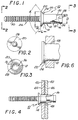
- FIGS. 1 through 3 show a tacking fastener 10 of the present invention.
- the tacking fastener 10 is typically used to temporarily fasten together two adjacent workpieces.
- the fastener 10 includes a shank 12 which has a first end 14, a second end 16 and an inner channel 18 that extends through the shank 12. Extending from the first end 14 of the shank 12 is a conical shaped head 20.
- the head 20 has an annular lip portion 22 that is separated from the first end 14 by a tapered portion 24.
- the fastener 10 includes a pull stem 26 that extends through the inner channel 18 of the shank 12.
- the pull stem 26 has a stem head 28 that is located adjacent to the second end 16 of the shank 12.
- the stem 26 also has a serrated pull portion 30 that can be gripped by a pull gun (not shown) to pull the head 28 through the inner channel 18 of the shank 12.
- the stem head 28 may have a tapered portion 32 which leads the head 28 into the inner channel 34.
- the tapered portion 32 extends to an annular tip portion 34.
- the tip portion 34 typically has a diameter larger than the diameter of the inner channel 18 so that the head 28 expands the shank 12 as the stem 26 is pulled through the channel 18.
- the stem head 28 may have an inner cavity 36 which allows the head 28 to contract as the stem 26 is pulled through the shank 12, particularly as the shank expands tightly into the surrounding hole in the work pieces.
- the shank 12 is constructed from an aluminum material and the pull stem 26 is constructed from a steel material.
- the fastener 10 preferably has the dimensions listed in Table I. Various embodiments are listed, each embodiment corresponding to a particular size of permanent fastener which will replace the tacking fastener 10. For example, the first row of values provide dimensions for a tacking fastener 10 that corresponds to a permanent fastener which has a 39.67 millimeter (0.1562 inch) diameter, the second row relates to a permanent fastener diameter of 47.63 millimeter (0.1875 inch) and so forth and so on. All dimensions are in millimeters and (inches).
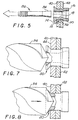
- Figures 4 through 8 show the installation of a fastener 10 to temporarily attach a first workpiece 40 to an adjacent second workpiece 42.
- the first workpiece 40 typically has an outer flat surface 44.
- the second workpiece 42 has a blind surface 46.
- the blind surface 46 is typically inaccessible to the operator installing the fastener 10.
- a hole 48 is initially drilled through the first 40 and second 42 workpieces.
- the hole 48 is typically larger than the diameter of the shank 12 so that the shank 12 and stem head 28 can be easily inserted into the workpieces 40 and 42.
- the stem head 28 and second end 16 of the shank 12 extend from the blind surface 46 of the second workpiece 42.
- the stem 26 is pulled through the shank 12.
- the stem head 28 initially expands the second end 16 of the shank 12 to create an upset portion 50 which bears against the second workpiece 42.
- the head 28 expands the inner shank portion 52 into tight engagement with the parts 40 and 42. Movement of the head 28 through the workpieces also contracts the annular tip portion 34 into the head cavity 36 to reduce the diameter of the stem head 28.
- the resultant inner channel 18 is thus smaller in the shank portion 52 than the upset portion 50.
- the conical head 20 is seated into the first workpiece 40 when the stem 26 is pulled through the shank 12.
- the tapered surface 24 of the head 20 will center the shank 12 with a hole 48 even when the hole diameter varies from a nominal dimension.
- the installed fastener 10 typically holds together the first 40 and second 42 workpieces while an operator installs permanent fasteners into the workpieces 40 and 42.
- the temporary fastener 10 is eventually removed and replaced with a permanent fastener.
- a drill bit 54 drills through the head 20, the shank 12 and the workpieces 40 and 42 to remove the temporary fastener 10 and create a hole for a permanent fastener (not shown).
- the head 20 has a diameter that is smaller than the diameter of the drill bit 54. The smaller head diameter reduces the possibility of the head material splintering and otherwise sticking to the drill 54 and scratching the outer surface 44. Additionally, the conical shape of the head 20 reduces the amount of fastener material that is removed by the drill and thus reduces the amount of drill chips produced during the drilling operation.
- the expanded shank 12 is in tight engagement with the workpieces so that the fastener does not spin during the drill process.
- the angle A of the conical head 20 is preferably different than the drill angle of the drill bit 54. The different angles reduce the amount of slippage between the bit 54 and the head 20. In the preferred embodiment, the angle A is 100°, with the corresponding angle of the drill being 120°. This assures that the head will finally drill out from outer diameter to inner diameter, thereby preventing the separation of a washer-like section of the head to clog the drill and cause the same to stop drilling, and perhaps to wander to damage the work piece.
- the present invention thus provides a temporary fastener that does not spin or create scratches on the workpiece when removed by a drill.
Landscapes
- Engineering & Computer Science (AREA)
- General Engineering & Computer Science (AREA)
- Mechanical Engineering (AREA)
- Drilling Tools (AREA)
- Insertion Pins And Rivets (AREA)
- Percussive Tools And Related Accessories (AREA)
Claims (8)
- Un procédé de création d'un trou pour un élément de fixation pcrmanent qui fixe une première pièce façonnée sur une deuxième pièce façonnéc adjacentc, comprenant :a) la fourniture d'un premier élément de fixation provisoire (10) comprenant un téton (12) ayant un canal intérieur (18), une première extrémité (14), une deuxième extrémité (16) et une tête de téton (20) s'étendant depuis ladite première extrémité (14), ledit élément de fixation provisoire (10) comprenant en outre une tige (26) qui s'étend à travers ledit canal intérieur (18) dudit téton (12) et comporte une tête (28) placée au voisinage de ladite deuxième extrémité (16) dudit téton (12);b) le perçagc d'un premier trou (48) dans la première pièce façonnée (40) et la deuxième pièce façonnée (42) ; etc) l'insertion dudit téton (12) et de ladite tige (26) dans ledit premier trou (48) de manière que ladite tête de tige (28) s'étende depuis la deuxièmc pièce façonnée (42) et quc ladite tête de téton (20) soit adjacente à la première pièce façonnée (40); et caractérisé pard) la traction de ladite tôte de tige (28) à travers ledit canal intérieur (18) pour faire s'expanscr ledit téton (12) et fixer ledit téton (12) sur la première pièce façonnée (40) et la deuxièmc pièce façonnée (42); ete) le perçage de ladite tête de téton (20), ledit téton (12), la première pièce façonnée (40) et la deuxième pièce façonnée (42) avec un foret (54) d'un diamètre supérieur au diamètre de ladite tête de téton (20).
- Le procédé selon la revendication 1, dans lequel ladite tète de téton (20) est une tête à forme conique.
- Le procédé selon la revendication 2, dans lequel ledit foret (54) a un angle de perçage différent de l'angle (A) de ladite tête à forme conique.
- Le procédé selon les revendications 1 à 3, dans lequel ladite tête de téton (20) s'étend depuis la surface cxtérieure (44) de la première pièce façonnée (40).
- Le procédé selon les revendications 1 à 4, dans lequel ladite tetc de tige (28) est fléchic lorsque ladite tête de tige (28) est tirée à travers ledit canal intérieur (18) dudit téton (12).
- Le procédé selon les revendications 1 à 5, dans lequel l'expansion du téton (12) comprend l'expansion d'une partie du téton (52) enclos par les pièces façonnées.
- Le procédé selon les revendications 1 à 6, comprenant en outre l'étape d'insertion d'un élément de fixation permanent après l'étape (e).
- Le procédé selon les revendications 1 à 7, dans lequel la première pièce façonnée (40) a une surface extérieure (44) plate.
Applications Claiming Priority (3)
| Application Number | Priority Date | Filing Date | Title |
|---|---|---|---|
| US58411196A | 1996-01-11 | 1996-01-11 | |
| US584111 | 1996-01-11 | ||
| PCT/US1997/000094 WO1997025538A1 (fr) | 1996-01-11 | 1997-01-09 | Fixation provisoire |
Publications (3)
| Publication Number | Publication Date |
|---|---|
| EP0873476A1 EP0873476A1 (fr) | 1998-10-28 |
| EP0873476A4 EP0873476A4 (fr) | 1999-03-03 |
| EP0873476B1 true EP0873476B1 (fr) | 2001-11-28 |
Family
ID=24335981
Family Applications (1)
| Application Number | Title | Priority Date | Filing Date |
|---|---|---|---|
| EP97901334A Expired - Lifetime EP0873476B1 (fr) | 1996-01-11 | 1997-01-09 | Fixation provisoire |
Country Status (8)
| Country | Link |
|---|---|
| US (1) | US5689873A (fr) |
| EP (1) | EP0873476B1 (fr) |
| JP (1) | JP2000505526A (fr) |
| AU (1) | AU1525597A (fr) |
| CA (1) | CA2242565C (fr) |
| DE (1) | DE69708595T2 (fr) |
| ES (1) | ES2169346T3 (fr) |
| WO (1) | WO1997025538A1 (fr) |
Cited By (1)
| Publication number | Priority date | Publication date | Assignee | Title |
|---|---|---|---|---|
| CN105351318A (zh) * | 2010-07-22 | 2016-02-24 | 阿弗德尔英国有限公司 | 外部有键条的紧固件 |
Families Citing this family (31)
| Publication number | Priority date | Publication date | Assignee | Title |
|---|---|---|---|---|
| DE19536982A1 (de) * | 1995-10-04 | 1997-04-17 | Deutsche Forsch Luft Raumfahrt | Verfahren und Vorrichtung zur Übertragung von Kräften zwischen zwei Fügeteilen |
| AU1923397A (en) * | 1996-01-27 | 1997-08-20 | Manfred Diels | Method of manufacturing cooling devices made up of several metal shaped-section elements for mounting on semiconductor components, shaped-section elements for use in the manufacture of such cooling devices and cooling devices manufactured by the method |
| US6010274A (en) * | 1997-06-03 | 2000-01-04 | Chrysler Corporation | Method and apparatus for attaching a stud to a member |
| US5979933A (en) * | 1998-04-13 | 1999-11-09 | Larry J. Winget | Air bag cover assembly including a switch fastenable to an air bag housing assembly |
| AU6147899A (en) * | 1998-09-16 | 2000-04-03 | Alan J. Babb | Acoustic loudspeaker with structures for selectively dampening sound |
| US6171038B1 (en) * | 1998-11-12 | 2001-01-09 | Textron Inc. | Tapered shank rivet |
| DE10026104A1 (de) | 1999-06-15 | 2000-12-28 | Eads Airbus Gmbh | Heftblindniet aus Leichtmetall,vorzugsweise für den Flugzeugbau |
| US6637995B1 (en) * | 2000-02-09 | 2003-10-28 | Patrick Michel White | Super-elastic rivet assembly |
| GB2378739A (en) | 2001-08-16 | 2003-02-19 | Emhart Inc | Blind rivet having undercut flange |
| DE10141988C1 (de) * | 2001-08-28 | 2003-01-09 | Manfred Diels | Verfahren zur Herstellung von Kühlkörpern |
| US20030082025A1 (en) * | 2001-10-18 | 2003-05-01 | Ralph Luhm | Blind fasteners and installation methods and apparatus |
| US6746192B2 (en) | 2001-12-27 | 2004-06-08 | Textron Inc. | Anti-rotation tacking rivet having ribs |
| GB2388412A (en) | 2002-05-08 | 2003-11-12 | Emhart Llc | Blind rivet |
| CA2410110A1 (fr) * | 2002-10-29 | 2004-04-29 | C.G. Air Systemes Inc. | Fixations decoratives creuses pour ouvertures pratiquees dans les baignoires equipees d'un systeme de massage par l'air |
| US20050055763A1 (en) * | 2002-10-29 | 2005-03-17 | Miguel Castellote | Hollow decorative fastener for openings defined in shell of bathtub provided with an air massage system |
| US20050281633A1 (en) * | 2004-06-16 | 2005-12-22 | Huck International, Inc. | Two-piece, corrosion-resistant, locking blind fastener |
| US8661683B2 (en) | 2006-08-29 | 2014-03-04 | The Boeing Company | Method and apparatus for preventing lightning strike damage to a structural component |
| US7824141B2 (en) * | 2007-08-03 | 2010-11-02 | Newfrey Llc | Blind rivet |
| US8096742B2 (en) | 2007-08-03 | 2012-01-17 | Newfrey Llc | Blind rivet |
| DE102010017296A1 (de) | 2010-06-08 | 2011-12-08 | Newfrey Llc | Blindniet und Befestigungsanordnung mit einem Blindniet |
| US20120034045A1 (en) * | 2010-08-06 | 2012-02-09 | Allfast Fastening Systems, Inc. | Temporary Rivet |
| JP2012077769A (ja) * | 2010-09-30 | 2012-04-19 | Nippon Pop Rivets & Fasteners Ltd | ブラインドリベット及びその締結方法 |
| GB2490713B (en) * | 2011-05-11 | 2013-05-01 | Infastech Ip Pte Ltd | Splined fastener |
| US20130004263A1 (en) * | 2011-06-29 | 2013-01-03 | United Technologies Corporation | Rivet and rivet removal method thereof |
| CN102913519A (zh) * | 2012-09-27 | 2013-02-06 | 贵州航太精密制造有限公司 | 一种座圈与夹层板的连接装置 |
| JP6048733B2 (ja) * | 2012-10-31 | 2016-12-21 | ポップリベット・ファスナー株式会社 | ブラインドリベット及びそれを使用した封止構造 |
| DE102015120278A1 (de) | 2015-11-24 | 2017-05-24 | Newfrey Llc | Blindnietanordnung und Blindnietverfahren |
| FR3046137B1 (fr) * | 2015-12-23 | 2018-02-16 | Airbus Operations | Procede d'alignement d'un premier orifice d'une premiere piece avec un deuxieme orifice d'une deuxieme piece et kit pour sa mise en œuvre |
| US11384783B2 (en) | 2017-10-31 | 2022-07-12 | Allfast Fastening Systems | Chip break bolt head |
| WO2019133701A1 (fr) | 2017-12-27 | 2019-07-04 | Allfast Fastening Systems | Élément de fixation par agrafage |
| EP3969764B1 (fr) * | 2019-05-15 | 2024-11-06 | Howmet Aerospace Inc. | Éléments de fixation en aveugle et procédés de fixation |
Family Cites Families (97)
| Publication number | Priority date | Publication date | Assignee | Title |
|---|---|---|---|---|
| US1120411A (en) * | 1914-03-11 | 1914-12-08 | Cinch Expansion Bolt & Engineering Company | Lead-packed anchor device. |
| US1941551A (en) * | 1930-02-27 | 1934-01-02 | Flannery Bolt Co | Staybolt cap removing tool |
| USRE21058E (en) * | 1931-06-17 | 1939-04-25 | Rivet and method of setting | |
| USRE20055E (en) * | 1932-03-31 | 1936-08-04 | Rivet and method of setting | |
| USRE22792E (en) * | 1932-08-03 | 1946-09-17 | Riveted structure and method of | |
| GB472329A (en) * | 1936-03-26 | 1937-09-22 | A T S Company Ltd | Improvements in and relating to rivets and rivetting |
| GB510482A (en) * | 1938-05-30 | 1939-08-02 | Roe A V & Co Ltd | Improvements in rivets and tools for removing rivets |
| US2385886A (en) * | 1942-11-05 | 1945-10-02 | Cherry Rivet Company | Rivet |
| GB578363A (en) * | 1944-12-14 | 1946-06-25 | British United Shoe Machinery | Improvements in or relating to rivetting |
| US2546602A (en) * | 1945-05-14 | 1951-03-27 | Cherry Rivet Company | Rivet with self-locking mandrel |
| US2538623A (en) * | 1945-05-14 | 1951-01-16 | Cherry Rivet Company | Rivet assembly |
| US2545752A (en) * | 1946-08-09 | 1951-03-20 | Bendix Aviat Corp | Rivet |
| US2652741A (en) * | 1950-08-04 | 1953-09-22 | Cherry Rivet Company | Blind rivet with clincher |
| US2756624A (en) * | 1952-05-06 | 1956-07-31 | Lockheed Aircraft Corp | Blind rivet with locked mandrel |
| AT209142B (de) * | 1958-08-12 | 1960-05-25 | Ludwig Kraemer | Blindnietverbindung |
| US3038626A (en) * | 1960-07-19 | 1962-06-12 | Townsend Company | Mechanism for setting rivets |
| US3178989A (en) * | 1962-02-26 | 1965-04-20 | Olympic Screw & Rivet Corp | Blind rivet with setting pin having successively deeper locking grooves |
| NL128418C (fr) * | 1963-08-30 | |||
| US3300798A (en) * | 1964-03-10 | 1967-01-31 | Textron Ind Inc | Blind sealing rivet and method of making the same |
| US3309747A (en) * | 1964-10-27 | 1967-03-21 | United Shoe Machinery Corp | Fastening devices |
| US3285121A (en) * | 1965-05-19 | 1966-11-15 | Siebol George | Blind rivet |
| US3348444A (en) * | 1965-10-28 | 1967-10-24 | United Shoe Machinery Corp | Expansion fastener with dual threaded engagement means |
| US3553040A (en) * | 1967-09-21 | 1971-01-05 | Star Expansion Ind Corp | Method for surface treatment of blind rivets |
| US3515419A (en) * | 1968-07-01 | 1970-06-02 | Huck Mfg Co | Container fastener |
| US3643544A (en) * | 1969-02-27 | 1972-02-22 | Nat Screw & Mfg Co The | High-strength structural blind fastener for use in airplanes, rockets and the like |
| US3657957A (en) * | 1969-11-24 | 1972-04-25 | Olympic Screw & Rivet Corp | Rivet |
| CA995500A (en) * | 1972-04-17 | 1976-08-24 | George Siebol | Blind rivet with recessed expanding head |
| US3880042A (en) * | 1972-05-02 | 1975-04-29 | Lloyd Sylvester Binns | Blind rivet |
| US3937123A (en) * | 1974-04-08 | 1976-02-10 | Textron Inc. | Blind fastener with shear washer |
| DE2442292C2 (de) * | 1974-09-04 | 1984-04-26 | Mecano-Simmonds Gmbh, 6900 Heidelberg | Blindniet |
| GB1517624A (en) * | 1975-02-25 | 1978-07-12 | Nichiei Bussan Co Ltd | Blind rivet |
| GB1548880A (en) * | 1975-07-23 | 1979-07-18 | Tucker Fasteners Ltd | Blind riveting |
| US4170919A (en) * | 1975-11-17 | 1979-10-16 | Olympic Fastening Systems, Inc. | Blind spacer fastener |
| US4170920A (en) * | 1975-11-17 | 1979-10-16 | Olympic Fastening Systems, Inc. | Blind spacer fastener |
| CA1061614A (fr) * | 1975-11-17 | 1979-09-04 | George Siebol | Attache borgne d'ecartement |
| US4168650A (en) * | 1976-06-25 | 1979-09-25 | Sps Technologies, Inc. | Blind fastener |
| US4089249A (en) * | 1976-09-27 | 1978-05-16 | Binns Lloyd Sylvester | Hole filling blind rivet |
| CA1096666A (fr) * | 1976-12-10 | 1981-03-03 | Dieter Mauer | Attache |
| US4293258A (en) * | 1977-10-04 | 1981-10-06 | Microdot Inc. | Self drilling blind rivet |
| US4364697A (en) * | 1977-12-12 | 1982-12-21 | Sps Technologies, Inc. | Blind fastener assembly |
| US4230017A (en) * | 1978-10-12 | 1980-10-28 | Huck Manufacturing Company | Pull-type blind fastener construction |
| US4312613A (en) * | 1979-05-11 | 1982-01-26 | Binns Lloyd Sylvester | Blind rivet assembly |
| CA1162087A (fr) * | 1979-06-07 | 1984-02-14 | Ludwig Kraemer | Rivet borgne |
| GB2056609B (en) * | 1979-08-14 | 1983-07-20 | Avdel Ltd | Blind fastener and method of manufacture thereof |
| US4370081A (en) * | 1979-08-16 | 1983-01-25 | Briles Franklin S | Blind fastener with work gripping head |
| US4407619A (en) * | 1979-09-20 | 1983-10-04 | Olympic Fastening Systems | Blind fastener with deformable clamping means |
| DE3035867A1 (de) * | 1979-09-28 | 1981-04-16 | Aerpat Ag, Zug | Selbstverstopfender blindniet |
| US4388031A (en) * | 1980-10-03 | 1983-06-14 | Rodgers Earl T | Blind fastener device |
| US4451189A (en) * | 1981-03-12 | 1984-05-29 | Monogram Industries, Inc. | Bulb rivet |
| US4579491A (en) * | 1981-12-28 | 1986-04-01 | Sps Technologies | Blind fastener assembly |
| CH654762A5 (en) * | 1982-04-05 | 1986-03-14 | Hanspeter Breu | Method and device for removing a loose-fitting rivet from the rivet hole |
| US4556351A (en) * | 1982-04-26 | 1985-12-03 | Phillips Plastics Corporation | Expansion rivet assembly |
| US4863325A (en) * | 1982-09-28 | 1989-09-05 | Huck Manufacturing Company | Two piece blind fastener with lock spindle construction |
| US4473914A (en) * | 1982-09-30 | 1984-10-02 | Huck Manufacturing Company | Method and apparatus for manufacturing a stop and lock shoulder for a blind fastener sleeve |
| GB2136075B (en) * | 1983-03-07 | 1986-11-05 | Avdel Ltd | Rivet |
| US4627775A (en) * | 1983-09-01 | 1986-12-09 | Huck Manufacturing Company | Blind fastener with grip compensating means |
| US4836728A (en) * | 1983-11-15 | 1989-06-06 | Emhart Industries, Inc. | Blind-riveting assembly |
| GB2151738B (en) * | 1983-11-17 | 1987-05-07 | Avdel Ltd | Self-plugging blind rivet |
| DE3343786A1 (de) * | 1983-12-03 | 1985-06-13 | Tucker Gmbh, 6300 Giessen | Blindniet nach dem ziehtyp |
| GB2155578B (en) * | 1984-03-13 | 1987-10-14 | Burroughs Corp | Tamper-proof blind rivet assembly |
| US4609315A (en) * | 1984-03-19 | 1986-09-02 | Briles Franklin S | Corrosion resistant dual tapered head fastener and panel composite |
| US4919576A (en) * | 1984-09-04 | 1990-04-24 | Allfast Fastening Systems, Inc. | Locking apparatus for blind fasteners |
| US4859128A (en) * | 1985-04-26 | 1989-08-22 | Microdot Inc. | Sheathed composite blind rivet |
| US4784551A (en) * | 1985-05-24 | 1988-11-15 | Huck Manufacturing Company | Fastening system and method for flush and protruding head blind fasteners with common pin and particularly such fasteners constructed of exotic material |
| US4609317A (en) * | 1985-06-12 | 1986-09-02 | Huck Manufacturing Company | Fastening system including a pull type fastener for constructing articles such as shipping containers and the like |
| US4615655A (en) * | 1985-06-12 | 1986-10-07 | Huck Manufacturing Company | Pull type fastener and fastening system for constructing articles such as shipping containers and the like |
| US4789283A (en) * | 1985-07-02 | 1988-12-06 | Pavco Industries, Inc. | Fluid-tight blind rivet |
| GB8517659D0 (en) * | 1985-07-12 | 1985-08-21 | Avdel Ltd | Self-plugging blind fastener |
| US4702655A (en) * | 1985-08-27 | 1987-10-27 | Huck Manufacturing Company | Fastening system including an improved interference fit blind fastener and method of manufacture |
| US4696610A (en) * | 1985-09-18 | 1987-09-29 | Wright Jewel L | Blind fastener |
| US4850771A (en) * | 1986-04-01 | 1989-07-25 | Hurd Ramon L | Installation system for securing workpieces of composite materials and the like and threaded fastener for such system |
| DE3612478A1 (de) * | 1986-04-14 | 1987-10-15 | Tucker Gmbh | Metall-blindniet |
| US4678384A (en) * | 1986-06-13 | 1987-07-07 | Lockheed Corporation | Controlled expansion blind fastener design |
| US4826372A (en) * | 1986-08-06 | 1989-05-02 | Victor Pastushin | Pre-locked pull-type blind fastener |
| US4736560A (en) * | 1986-12-01 | 1988-04-12 | Engineered Construction Components (America) | Peel rivet |
| GB8702155D0 (en) * | 1987-01-30 | 1987-03-04 | Avdel Ltd | Break-stem blind rivet |
| US4877363A (en) * | 1987-02-10 | 1989-10-31 | Hi-Shear Corporation | Blind fastener |
| US4765787A (en) * | 1987-03-16 | 1988-08-23 | Briles Franklin S | Blind fastener positively locking to work, and employing interior locking ring |
| GB2202293A (en) * | 1987-03-19 | 1988-09-21 | Avdel Ltd | Releasable rivets |
| US4968198A (en) * | 1987-05-26 | 1990-11-06 | Binns Lloyd Sylvester | Buckling sleeve blind fastener |
| FR2622257B1 (fr) * | 1987-10-23 | 1990-03-16 | Aerospatiale | Procede d'assemblage de panneaux de grandes dimensions notamment par rivetage |
| GB2220454A (en) * | 1988-05-27 | 1990-01-10 | Avdel Ltd | Blind rivet |
| GB2220722A (en) * | 1988-07-14 | 1990-01-17 | Avdel Systems Ltd | Self-plugging blind fastener |
| US4900205A (en) * | 1988-08-15 | 1990-02-13 | Huck Manufacturing Co. | Blind fastener forming a blind head with a large effective area |
| GB2231932A (en) * | 1989-05-16 | 1990-11-28 | Milladale Ltd | Self-plugging blind rivet |
| FR2647166B1 (fr) * | 1989-05-19 | 1991-07-12 | Garonne Ets Auriol & Cie | Organe de rivetage aveugle, procede d'assemblage et assemblages obtenus |
| US4990042A (en) * | 1989-09-05 | 1991-02-05 | Szayer Geza J | Self-drilling blind setting rivet |
| US4950115A (en) * | 1989-10-02 | 1990-08-21 | Huck Manufacturing Company | Blind fastener with expandable sleeve forming a blind bulbed head with large bearing area and a pin having a controlled protrusion length |
| US5052870A (en) * | 1990-01-31 | 1991-10-01 | Textron, Inc. | Bulb fastener |
| US5006024A (en) * | 1990-03-05 | 1991-04-09 | George Siebol | Dual-lock blind fastener |
| US5044850A (en) * | 1990-05-11 | 1991-09-03 | Avdel Corporation | Self plugging blind rivet |
| US5141373A (en) * | 1990-08-15 | 1992-08-25 | Kendall James W | Flush breaking interference fit blind fastener |
| US5197838A (en) * | 1991-03-08 | 1993-03-30 | Manfred Schwab | Blind rivet with an apparatus engageable with conical shaped rivet pin and apparatus for setting such blind rivets |
| US5135340A (en) * | 1991-04-10 | 1992-08-04 | Hi-Shear Corporation | Bulged and swelled blind fastener |
| GB9203251D0 (en) * | 1992-02-15 | 1992-04-01 | Emhart Inc | Blind pin fixing |
| GB2269873A (en) * | 1992-08-21 | 1994-02-23 | Avdel Systems Ltd | Self-plugging blind fastener |
| GB2288648A (en) * | 1994-04-12 | 1995-10-25 | Avdel Systems Ltd | Removable rivet |
-
1996
- 1996-11-06 US US08/746,132 patent/US5689873A/en not_active Ceased
-
1997
- 1997-01-09 EP EP97901334A patent/EP0873476B1/fr not_active Expired - Lifetime
- 1997-01-09 ES ES97901334T patent/ES2169346T3/es not_active Expired - Lifetime
- 1997-01-09 WO PCT/US1997/000094 patent/WO1997025538A1/fr not_active Ceased
- 1997-01-09 DE DE69708595T patent/DE69708595T2/de not_active Expired - Lifetime
- 1997-01-09 JP JP9525301A patent/JP2000505526A/ja active Pending
- 1997-01-09 CA CA002242565A patent/CA2242565C/fr not_active Expired - Lifetime
- 1997-01-09 AU AU15255/97A patent/AU1525597A/en not_active Abandoned
Cited By (2)
| Publication number | Priority date | Publication date | Assignee | Title |
|---|---|---|---|---|
| CN105351318A (zh) * | 2010-07-22 | 2016-02-24 | 阿弗德尔英国有限公司 | 外部有键条的紧固件 |
| CN105351318B (zh) * | 2010-07-22 | 2017-12-08 | 阿弗德尔英国有限公司 | 外部有键条的紧固件 |
Also Published As
| Publication number | Publication date |
|---|---|
| DE69708595D1 (de) | 2002-01-10 |
| CA2242565A1 (fr) | 1997-07-17 |
| EP0873476A4 (fr) | 1999-03-03 |
| AU1525597A (en) | 1997-08-01 |
| JP2000505526A (ja) | 2000-05-09 |
| EP0873476A1 (fr) | 1998-10-28 |
| ES2169346T3 (es) | 2002-07-01 |
| US5689873A (en) | 1997-11-25 |
| WO1997025538A1 (fr) | 1997-07-17 |
| CA2242565C (fr) | 2003-01-28 |
| DE69708595T2 (de) | 2002-07-04 |
Similar Documents
| Publication | Publication Date | Title |
|---|---|---|
| US5689873A (en) | Tacking fastener | |
| WO1997025538A9 (fr) | Fixation provisoire | |
| US6746192B2 (en) | Anti-rotation tacking rivet having ribs | |
| US4580936A (en) | Blind rivet assembly | |
| KR101022132B1 (ko) | 블라인드 패스너 및 워크피스로부터 그것을 제거하는 방법 | |
| US6537005B1 (en) | Blind fastener | |
| US3965792A (en) | Split pintail fastener assembly | |
| USRE39582E1 (en) | Method for replacing a tacking fastener | |
| CA2057183A1 (fr) | Fixation avec dispositif d'installation a filetage interieur | |
| EP1327082B1 (fr) | Fixation en aveugle | |
| US4002099A (en) | Rivet | |
| EP0728950A1 (fr) | Procédé pour la fixation de deux éléments et dispositif de fixation associé | |
| EP0152532A1 (fr) | Méthode pour l'insertion d'un rivet aveugle | |
| GB2401662A (en) | Removable blind rivet | |
| GB2227538A (en) | Swageable tubular member |
Legal Events
| Date | Code | Title | Description |
|---|---|---|---|
| PUAI | Public reference made under article 153(3) epc to a published international application that has entered the european phase |
Free format text: ORIGINAL CODE: 0009012 |
|
| 17P | Request for examination filed |
Effective date: 19980707 |
|
| AK | Designated contracting states |
Kind code of ref document: A1 Designated state(s): DE ES FR GB IT |
|
| A4 | Supplementary search report drawn up and despatched | ||
| AK | Designated contracting states |
Kind code of ref document: A4 Designated state(s): DE ES FR GB IT |
|
| 17Q | First examination report despatched |
Effective date: 19991220 |
|
| GRAG | Despatch of communication of intention to grant |
Free format text: ORIGINAL CODE: EPIDOS AGRA |
|
| GRAG | Despatch of communication of intention to grant |
Free format text: ORIGINAL CODE: EPIDOS AGRA |
|
| GRAH | Despatch of communication of intention to grant a patent |
Free format text: ORIGINAL CODE: EPIDOS IGRA |
|
| GRAH | Despatch of communication of intention to grant a patent |
Free format text: ORIGINAL CODE: EPIDOS IGRA |
|
| GRAA | (expected) grant |
Free format text: ORIGINAL CODE: 0009210 |
|
| AK | Designated contracting states |
Kind code of ref document: B1 Designated state(s): DE ES FR GB IT |
|
| REG | Reference to a national code |
Ref country code: GB Ref legal event code: IF02 |
|
| ET | Fr: translation filed | ||
| REF | Corresponds to: |
Ref document number: 69708595 Country of ref document: DE Date of ref document: 20020110 |
|
| REG | Reference to a national code |
Ref country code: ES Ref legal event code: FG2A Ref document number: 2169346 Country of ref document: ES Kind code of ref document: T3 |
|
| PLBE | No opposition filed within time limit |
Free format text: ORIGINAL CODE: 0009261 |
|
| STAA | Information on the status of an ep patent application or granted ep patent |
Free format text: STATUS: NO OPPOSITION FILED WITHIN TIME LIMIT |
|
| 26N | No opposition filed | ||
| REG | Reference to a national code |
Ref country code: FR Ref legal event code: PLFP Year of fee payment: 20 |
|
| PGFP | Annual fee paid to national office [announced via postgrant information from national office to epo] |
Ref country code: ES Payment date: 20151214 Year of fee payment: 20 Ref country code: FR Payment date: 20151208 Year of fee payment: 20 |
|
| PGFP | Annual fee paid to national office [announced via postgrant information from national office to epo] |
Ref country code: DE Payment date: 20160105 Year of fee payment: 20 Ref country code: IT Payment date: 20160127 Year of fee payment: 20 |
|
| PGFP | Annual fee paid to national office [announced via postgrant information from national office to epo] |
Ref country code: GB Payment date: 20160106 Year of fee payment: 20 |
|
| REG | Reference to a national code |
Ref country code: DE Ref legal event code: R071 Ref document number: 69708595 Country of ref document: DE |
|
| REG | Reference to a national code |
Ref country code: GB Ref legal event code: PE20 Expiry date: 20170108 |
|
| REG | Reference to a national code |
Ref country code: ES Ref legal event code: FD2A Effective date: 20170426 |
|
| PG25 | Lapsed in a contracting state [announced via postgrant information from national office to epo] |
Ref country code: GB Free format text: LAPSE BECAUSE OF EXPIRATION OF PROTECTION Effective date: 20170108 |
|
| PG25 | Lapsed in a contracting state [announced via postgrant information from national office to epo] |
Ref country code: ES Free format text: LAPSE BECAUSE OF EXPIRATION OF PROTECTION Effective date: 20170110 |