EP0873477B1 - Verbesserungen an befestigungsvorrichtungen - Google Patents
Verbesserungen an befestigungsvorrichtungen Download PDFInfo
- Publication number
- EP0873477B1 EP0873477B1 EP96940003A EP96940003A EP0873477B1 EP 0873477 B1 EP0873477 B1 EP 0873477B1 EP 96940003 A EP96940003 A EP 96940003A EP 96940003 A EP96940003 A EP 96940003A EP 0873477 B1 EP0873477 B1 EP 0873477B1
- Authority
- EP
- European Patent Office
- Prior art keywords
- collet
- legs
- bore
- tube
- assembly according
- Prior art date
- Legal status (The legal status is an assumption and is not a legal conclusion. Google has not performed a legal analysis and makes no representation as to the accuracy of the status listed.)
- Expired - Lifetime
Links
- 239000004033 plastic Substances 0.000 claims abstract description 12
- 229920003023 plastic Polymers 0.000 claims abstract description 12
- 239000000463 material Substances 0.000 claims abstract description 9
- 238000003780 insertion Methods 0.000 claims abstract description 6
- 230000037431 insertion Effects 0.000 claims abstract description 6
- 229910000639 Spring steel Inorganic materials 0.000 claims description 2
- 230000000694 effects Effects 0.000 description 4
- 239000002184 metal Substances 0.000 description 3
- 238000004873 anchoring Methods 0.000 description 2
- 238000010276 construction Methods 0.000 description 1
- 230000008878 coupling Effects 0.000 description 1
- 238000010168 coupling process Methods 0.000 description 1
- 238000005859 coupling reaction Methods 0.000 description 1
- 230000002708 enhancing effect Effects 0.000 description 1
- 238000001125 extrusion Methods 0.000 description 1
- 239000011152 fibreglass Substances 0.000 description 1
- 238000001746 injection moulding Methods 0.000 description 1
- 238000009434 installation Methods 0.000 description 1
- 238000004519 manufacturing process Methods 0.000 description 1
- 230000002093 peripheral effect Effects 0.000 description 1
Images

Classifications
-
- E—FIXED CONSTRUCTIONS
- E06—DOORS, WINDOWS, SHUTTERS, OR ROLLER BLINDS IN GENERAL; LADDERS
- E06C—LADDERS
- E06C7/00—Component parts, supporting parts, or accessories
- E06C7/08—Special construction of longitudinal members, or rungs or other treads
- E06C7/082—Connections between rungs or treads and longitudinal members
- E06C7/086—Connections between rungs or treads and longitudinal members with a connecting piece inserted in a hollow rung
-
- F—MECHANICAL ENGINEERING; LIGHTING; HEATING; WEAPONS; BLASTING
- F16—ENGINEERING ELEMENTS AND UNITS; GENERAL MEASURES FOR PRODUCING AND MAINTAINING EFFECTIVE FUNCTIONING OF MACHINES OR INSTALLATIONS; THERMAL INSULATION IN GENERAL
- F16B—DEVICES FOR FASTENING OR SECURING CONSTRUCTIONAL ELEMENTS OR MACHINE PARTS TOGETHER, e.g. NAILS, BOLTS, CIRCLIPS, CLAMPS, CLIPS OR WEDGES; JOINTS OR JOINTING
- F16B37/00—Nuts or like thread-engaging members
- F16B37/04—Devices for fastening nuts to surfaces, e.g. sheets, plates
- F16B37/041—Releasable devices
- F16B37/043—Releasable devices with snap action
-
- H—ELECTRICITY
- H02—GENERATION; CONVERSION OR DISTRIBUTION OF ELECTRIC POWER
- H02G—INSTALLATION OF ELECTRIC CABLES OR LINES, OR OF COMBINED OPTICAL AND ELECTRIC CABLES OR LINES
- H02G3/00—Installations of electric cables or lines or protective tubing therefor in or on buildings, equivalent structures or vehicles
- H02G3/02—Details
- H02G3/04—Protective tubing or conduits, e.g. cable ladders or cable troughs
- H02G3/0456—Ladders or other supports
-
- F—MECHANICAL ENGINEERING; LIGHTING; HEATING; WEAPONS; BLASTING
- F16—ENGINEERING ELEMENTS AND UNITS; GENERAL MEASURES FOR PRODUCING AND MAINTAINING EFFECTIVE FUNCTIONING OF MACHINES OR INSTALLATIONS; THERMAL INSULATION IN GENERAL
- F16B—DEVICES FOR FASTENING OR SECURING CONSTRUCTIONAL ELEMENTS OR MACHINE PARTS TOGETHER, e.g. NAILS, BOLTS, CIRCLIPS, CLAMPS, CLIPS OR WEDGES; JOINTS OR JOINTING
- F16B2200/00—Constructional details of connections not covered for in other groups of this subclass
- F16B2200/40—Clamping arrangements where clamping parts are received in recesses of elements to be connected
- F16B2200/403—Threaded clamping parts
-
- Y—GENERAL TAGGING OF NEW TECHNOLOGICAL DEVELOPMENTS; GENERAL TAGGING OF CROSS-SECTIONAL TECHNOLOGIES SPANNING OVER SEVERAL SECTIONS OF THE IPC; TECHNICAL SUBJECTS COVERED BY FORMER USPC CROSS-REFERENCE ART COLLECTIONS [XRACs] AND DIGESTS
- Y10—TECHNICAL SUBJECTS COVERED BY FORMER USPC
- Y10T—TECHNICAL SUBJECTS COVERED BY FORMER US CLASSIFICATION
- Y10T403/00—Joints and connections
- Y10T403/60—Biased catch or latch
- Y10T403/606—Leaf spring
-
- Y—GENERAL TAGGING OF NEW TECHNOLOGICAL DEVELOPMENTS; GENERAL TAGGING OF CROSS-SECTIONAL TECHNOLOGIES SPANNING OVER SEVERAL SECTIONS OF THE IPC; TECHNICAL SUBJECTS COVERED BY FORMER USPC CROSS-REFERENCE ART COLLECTIONS [XRACs] AND DIGESTS
- Y10—TECHNICAL SUBJECTS COVERED BY FORMER USPC
- Y10T—TECHNICAL SUBJECTS COVERED BY FORMER US CLASSIFICATION
- Y10T403/00—Joints and connections
- Y10T403/75—Joints and connections having a joining piece extending through aligned openings in plural members
Definitions
- This invention relates to fastening devices, for the connecting of two members together, and the invention has particular application to the connecting of rungs and rails of cable management ladders which are manufactured from synthetic plastic materials in particular glass reinforced plastics materials and of which the rails and rungs are formed by extrusion or pultrusion.
- These fastening devices require to provide a strong coupling, as the cable management ladders are often suspended at high levels and can carry large amounts of weighty cables and pipes. Also although not intended workmen will often use the ladders for supporting their weight for example in cases of emergency or need.
- GRP cable ladders comprise side rails and rungs, and the rungs, of the type to which the present invention relates, are tubular members which are "closed” insofar as in cross section they have continuous peripheries or in other words they are not provided with any longitudinal slots, or are provided with such slots or are channel sectioned in which case they will also be provided with peripheral anti-splaying holding bands or ferrules, making them in effect "closed”, and the expression "closed” as used hereinafter is intended to cover all such arrangements.
- the invention has particular and exclusive application to the connecting of these tubular members to other members. In relation to the cable ladders therefore reference will be made to closed rungs which will be understood to be constructed as described above.
- the side rails to which the closed rungs are connected in GRP cable ladders typically are of channel section and comprise a base portion and side flanges. There may be one or more intermediate flanges between the side flanges to split the rail into several cavities.
- the ends of the rungs abut the inner base surfaces, and fixing of the rungs is effected by boring a fixing aperture through at least one of the side or intermediate flanges, and opposed locations through the rung end, and then a fixing bolt is passed through the aligned apertures and is secured by means of a nut and a washer.
- the head of the bolt will typically lie to the outside of side flange, and the nut will typically lie within the rail cavity.
- these fastenings require to provide secure connections which can take a significant load.
- FR-A-2343153 to ITW Fastex Italia SPA discloses a collet-type member for fastening two structural members together.
- the collet has a central bore through which a threaded screw can pass and engage internally of the collet with inwardly projecting tabs connected to respective external lugs which are intended to snap-fit into apertures provided in one of the members.
- the screw As the screw is threaded into the bore of the collet, it engages with the inwardly projecting tabs and thus urges the external lugs outwardly and into secure engagement with the recesses provided in the member in which the collet is disposed.
- the present invention seeks to provide a fixing or fastening device which is usable for connecting two members together, and which will provide a fastening of sufficient strength to be applicable to the connection of GRP cable ladder rails to GRP cable ladder rungs which are closed tubes.
- an assembly for a cable ladder comprises a closed tube and a second member attached there against by means of a fastening device and threaded fixing member, said fastening device being a plastic block defining a U-shaped collet having a base and a pair of legs which is inserted into an end of the closed tube with clearance but in neat fitting fashion, the base providing resiliency so that the legs at the free ends can be sprung together and pushed into the end of the closed tube, the tube having aperture or internal recess means in the walls thereof to receive pip or projection means extending outwardly on the legs of the collet, the collet furthermore having a bore which extends through the base, said threaded fixing member passing through a bore in a base section of said second member and into the bore of the collet, said bore being partially defined in the inner surfaces of each of said legs, wherein said bore is threaded over at least a substantial portion of the legs to receive said threaded fixing member after insertion of the collet into
- firm anchoring of the second member may be achieved in that the threaded bore has sufficient threads to achieve good anchoring of the threaded fixing member, in practice a bolt. Also, when the collet is first inserted it is preferred that the legs are slightly inclined towards each other so that the bore tapers. Thus, when the bolt is screwed into the collet, it forces the legs apart, enhancing the fixing effect by the combination of wedging and screwing.
- the said bore may be partially formed by an aperture in the common end, and opposed groves in the opposite faces of the legs.
- the collet preferably will be formed of a plastic material which has sufficient springiness to enable the legs to be resiliently deflected together, and to spring apart to perform the function as above described.
- the block forming collet may have a core of defined by one or more strips of spring steel around which the plastics material is formed, but in the preferred case, the block is a one piece injection moulding of plastics material.
- the second member may be a cable ladder side rail and for the connection of the side rail to the end of the closed rung in which the collet is provided, an aperture is simply provided in the base of the side rail, and then the bolt is passed through the aperture and into the collet bore. The bolt is tightened, causing the collet and therefore the end of the rung to be tightened against the inner surface of the base portion of the side rail forming a firm and secure anchor between the rung end and the side rail.
- the projection means on the collet may simply comprise cylindrical protrusions which are chamfered at one side to ease the insertion of the collet into the end of the closed tube, but the collet has best application in connection with tubes which are of sufficient wall thickness, such as GRP tubes to enable the pips to catch effectively in the recess or apertures.
- Fig. 1 shows the arrangement clearly, and in this figure a rail 10 of part of a GRP cable ladder made up of a pair of symmetrically arranged rails 10, and a plurality of transverse tubular rungs of which one is indicated by 12, is shown.
- the tubular rung is of square section in this example, although it could be of any appropriate configuration.
- the rail 10 comprises a base section 14 and a pair of flanges 16 and 18.
- the rung 12 is to be secured to the base section 14 and will usually be arranged in close abutting contact with either flange 16 or flange 18. In this case it will abut flange 18.
- the rail 12 is fixed to the base section 14 to the inside thereof by means of a bolt 20 and a special collet 22 according to the embodiment of the invention.
- the collet 22 is basically a block of rectangular cross section which is adapted to fit into the bore 24 of the rail 12 with clearance but in a neat fitting fashion.
- the collet is bifurcated, or U-shaped, in that it has a central slot 26 which defines two leg sections 28 and 30 which extend from a common end or base section 32.
- the block is such that the free ends of the legs can be resiliently pushed together in the direction indicated by the arrows 34 when it is desired to push the block into the end of the rung 12. This is necessary because on the outside of the legs there are projections 36 which extend beyond the general cross sectional shape of the block and in use engage in a pair of apertures 38 which are diametrically oppositely provided in the end of the rung 12.
- the block 22 finally is provided with a threaded bore 40 which extends for substantially the length of the block and which is for the receipt of the bolt 20.
- the collet legs 28 and 30 are pushed together as indicated by arrows 34, so that the end of the collet block facing the end of the rung is reduced in width, and it can be pushed in to the bore 24. It is pushed in so far until the projections 36 register with the apertures 38, and then the collet can spring back to or towards the original size with the projections 36 located in the holes 38. Now it is simply a matter of bringing the end of the rung 12 into register with a bore 42 in base section 14 of the rail 10, followed by threading the bolt through aperture 42 and into bore 40. The collet block tightens against the inner surface of the base of the rail 10, and pulls with it the rung 12 in that the projections 36 engage the edges of the apertures 38 form a lock.
- the rung 12 is also of GRP, and is of sufficient thickness so that the projections 36 will procure a positive hold on the edges of the apertures 38.
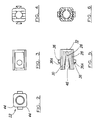
- the block 22 is shown in greater detail in Figs. 2 to 6, and it is to be noted that the thread of the bore lies mainly on the inner surfaces of the legs 28 and 30 and extends for the whole length thereof. It need not extend for all of the length but should extend for substantially all of the length to provide sufficient fastening effect, having regard to the fact that the threads are of plastic material.
- the block shown in these figures is a commonly used size of 18.5 mm 2 , in fact it can be of any suitable dimension.
- Block 22 is a square section apart from chamfered corners 44, and the slot 26 flares outwardly as at 46 towards the end opposite the common end 32. This is to enhance the squeezing together of the ends of the legs 28 and 30.
- the projections 36 are cylindrical, but are provided with chamfered sides 36A to enhance the insertion of the collet block into the end of the tube 12.
- the legs of the collet may be adapted to be slightly angled together so that the bore is of reducing cross section or may take up this configuration when first inserted in the tube end.
- the advantage of this is that as the bolt is screwed into the bore, so the legs are pushed apart providing a greater binding effect between the bolt and the collar.
- An extremely simple and effective fastening device is provided, and it is especially useful in connection with GRP cable ladders. It can of course be used in any appropriate application requiring strong fixing, where the end of a tubular member is to be connected to another member which lies transversely thereto.
- the advantage of the arrangement is that fitting is quick and no additional nuts are required for connection to the end of the bolt 20 at inaccessible locations.
- fixing is secure in that the threaded bore has a substantial number of threads making the danger of stripping of the threads and the loosening of the fastening unlikely.
Landscapes
- Engineering & Computer Science (AREA)
- Mechanical Engineering (AREA)
- General Engineering & Computer Science (AREA)
- Architecture (AREA)
- Civil Engineering (AREA)
- Structural Engineering (AREA)
- Ladders (AREA)
- Clamps And Clips (AREA)
- Details Of Indoor Wiring (AREA)
- Mutual Connection Of Rods And Tubes (AREA)
- Resistance Heating (AREA)
- Glass Compositions (AREA)
- Cylinder Crankcases Of Internal Combustion Engines (AREA)
- Connection Of Plates (AREA)
- Dowels (AREA)
Claims (9)
- Baugruppe für eine Kabelpritsche, umfassend eine geschlossene Röhre (12) und ein zweites Element (10), das daran mit einer Befestigungsvorrichtung (22) und einem Gewindefixierelement (20) angebracht wird, wobei die genannte Befestigungsvorrichtung (20) ein Kunststoffblock ist, der eine U-förmige Hülse mit einer Basis (32) und zwei Schenkeln (28, 30) definiert, die in ein Ende (24) der geschlossenen Röhre (12) mit Spielraum, aber gut sitzend eingesetzt wird, wobei die Basis (32) Elastizität aufweist, so dass die Schenkel (28, 30) an den freien Enden federnd zusammengedrückt und in das Ende der geschlossenen Röhre (12) geschoben werden können, wobei die Röhre eine Öffnung oder eine Innenausnehmung (38) in ihren Wänden aufweist, um eine Spitze oder einen Ansatz (36) aufzunehmen, die/der außen auf den Schenkeln (28, 30) der Hülse verläuft, wobei die Hülse ferner eine Bohrung (40) hat, die durch die Basis (32) verläuft, wobei das genannte Gewindefixierelement (20) durch eine Bohrung (42) in einem Basisstück des genannten zweiten Elementes (10) und in die Bohrung (40) der Hülse läuft, wobei die genannte Bohrung (40) teilweise in den Innenflächen der jeweiligen genannten Schenkel (28, 30) definiert ist, wobei die genannte Bohrung (40) über wenigstens einen erheblichen Abschnitt der Schenkel (28, 30) mit einem Gewinde versehen ist, um das genannte Gewindefixierelement (20) nach dem Einsetzen der Hülse in das Ende (24) der geschlossenen Röhre (12) aufzunehmen, so dass, während das Gewindefixierelement (20) in der Bohrung (40) der Hülse aufgenommen wird, die Schenkel (28, 30) der Hülse auseinandergedrückt werden und gegen die Innenfläche der geschlossen Röhre verkeilen, und sowohl Hülse (22) als auch geschlossene Röhre (12) in Richtung auf die Innenfläche des Basisabschnitts des zweiten Elementes (10) gezogen und daran befestigt werden.
- Baugruppe nach Anspruch 1, bei der die Hülse (22) derart gestaltet ist, dass, wenn sie zuerst in das Röhrenende (24) eingesetzt wird, die Schenkel (28, 30) geringfügig zueinander hin geneigt sind, so dass die Bohrung (40) konisch zuläuft.
- Baugruppe nach Anspruch 1 oder 2, bei der zwei der genannten Ansätze (36) auf der Außenseite der jeweiligen Schenkel vorhanden und so ausgestaltet sind, dass sie in zwei Öffnungen (38) in gegenüberliegenden Wänden der genannten geschlossenen Röhre (12) springen.
- Baugruppe nach Anspruch 1, 2 oder 3, bei der die genannte Bohrung (40) teilweise durch eine Öffnung im gemeinsamen Ende (32) und gegenüberliegende Rillen in den gegenüberliegenden Flächen der Schenkel (28, 30) gebildet wird.
- Baugruppe nach einem der vorherigen Ansprüche, bei der die Hülse (32) aus einem Kunststoffmaterial besteht, das eine ausreichende Federkraft aufweist, damit die Schenkel (28, 30) elastisch zusammengebogen werden können und beim Lösen auseinander springen.
- Baugruppe nach einem der Ansprüche 1 bis 4, bei der der Block, der die Hülse (32) bildet, einen Kern aufweist, der durch einen oder mehrere Streifen Federstahl definiert ist, um den/die das Kunststoffmaterial geformt ist.
- Baugruppe nach einem der vorherigen Ansprüche, bei der das zweite Element (10) eine Kabelpritschen-Seitenschiene ist, wobei die Seitenschiene (10) an den Enden der geschlossenen Sprossen (12) angeschlossen wird, in denen die Hülsen (32) vorgesehen sind, eine Öffnung (42) in der Basis der Seitenschiene (10) vorhanden ist und die Baugruppe durch Schrauben (20) vervollständigt wird, die durch die Öffnungen (42) und in die Hülsenbohrungen (40) laufen.
- Baugruppe nach einem der vorherigen Ansprüche, bei der der oder jeder Ansatz (36) an der Hülse einen zylindrischen Vorsprung umfasst, der auf einer Seite abgeschrägt ist, um das Einsetzen der Hülse in das Ende der geschlossenen Röhre zu erleichtem.
- Baugruppe nach einem der vorherigen Ansprüche, bei der die Hülsenschenkel (28, 30) auf ihrer Innenfläche so geformt sind, dass der die Schenkel trennende Raum von der Basis zu einer Position auf halbem Weg der Länge der Schenkel eine konstante Breite hat und dann allmählich von dieser Position zu den freien Enden der Schenkel breiter wird.
Applications Claiming Priority (3)
| Application Number | Priority Date | Filing Date | Title |
|---|---|---|---|
| GB9600638 | 1996-01-12 | ||
| GBGB9600638.2A GB9600638D0 (en) | 1996-01-12 | 1996-01-12 | Improvements relating to fastening devices |
| PCT/GB1996/002929 WO1997025541A1 (en) | 1996-01-12 | 1996-11-28 | Improvements relating to fastening devices |
Publications (2)
| Publication Number | Publication Date |
|---|---|
| EP0873477A1 EP0873477A1 (de) | 1998-10-28 |
| EP0873477B1 true EP0873477B1 (de) | 2001-02-28 |
Family
ID=10786959
Family Applications (1)
| Application Number | Title | Priority Date | Filing Date |
|---|---|---|---|
| EP96940003A Expired - Lifetime EP0873477B1 (de) | 1996-01-12 | 1996-11-28 | Verbesserungen an befestigungsvorrichtungen |
Country Status (9)
| Country | Link |
|---|---|
| US (1) | US6155741A (de) |
| EP (1) | EP0873477B1 (de) |
| AT (1) | ATE199439T1 (de) |
| AU (1) | AU705980B2 (de) |
| CA (1) | CA2242289C (de) |
| DE (1) | DE69611939T2 (de) |
| GB (1) | GB9600638D0 (de) |
| MY (1) | MY121585A (de) |
| WO (1) | WO1997025541A1 (de) |
Families Citing this family (26)
| Publication number | Priority date | Publication date | Assignee | Title |
|---|---|---|---|---|
| DE19849201A1 (de) * | 1998-10-26 | 2000-04-27 | Hilti Ag | Verbindungselement für Montageschienen |
| US6427858B2 (en) | 1999-01-19 | 2002-08-06 | Pro-Mart Industries, Inc. | Laundry drying rack |
| US6394292B1 (en) * | 1999-01-19 | 2002-05-28 | Pro-Mart Industries, Inc. | Laundry stand |
| DE29914940U1 (de) * | 1999-08-26 | 1999-11-11 | Lite-On Enclosure Inc., Taipeh/T'ai-Pei | Befestigungsvorrichtung eines Tastschalters an der Frontplatte eines PC's |
| DE10142508A1 (de) * | 2001-08-30 | 2003-03-27 | Bsh Bosch Siemens Hausgeraete | Rastvorrichtung und mit dieser ausgestattete Küchenmaschine |
| DE10154275A1 (de) * | 2001-11-05 | 2003-05-15 | Bsh Bosch Siemens Hausgeraete | Arretieren und Lösen einer Steckverbindung |
| DE10247636B4 (de) * | 2002-10-11 | 2004-11-04 | Edgar Rahmlow | Vorrichtung zum Festlegen eines Hohlprofiles oder eines Rohrabschnittes an einem Bauteil |
| US7695028B2 (en) * | 2002-11-07 | 2010-04-13 | Piolax, Inc. | Lock apparatus |
| DE10321098B4 (de) * | 2003-05-09 | 2012-04-19 | Wicona Bausysteme Gmbh | Verbinder für Eck- oder Stoßverbindungen zweier Hohlprofile |
| US7134647B2 (en) * | 2003-11-12 | 2006-11-14 | Digger Specialties, Inc. | Lock |
| US7152849B2 (en) * | 2003-11-12 | 2006-12-26 | Digger Specialties, Inc. | Fastener |
| US7182223B2 (en) * | 2004-03-29 | 2007-02-27 | S.C. Johnson & Son, Inc. | Detachable tube assembly |
| FR2886479B1 (fr) | 2005-05-27 | 2007-08-10 | Ebo Systems Soc Par Actions Si | Dispositif de support de cables electriques ou autres conduits |
| TWM297278U (en) * | 2006-02-27 | 2006-09-11 | Bau-Min Jiang | Inclined hole drilling mold for carpentry |
| DE102007014484B4 (de) * | 2006-03-22 | 2008-08-07 | Robert Strobel | Vorrichtung zum lösbaren Verbinden |
| KR100735140B1 (ko) | 2006-07-07 | 2007-07-06 | 주식회사 제이콘 | 사다리용 가로대 |
| CN201288493Y (zh) * | 2007-12-29 | 2009-08-12 | 冷鹭浩 | 一种梯子 |
| US8286810B2 (en) * | 2010-02-10 | 2012-10-16 | Pro-Mart Industries, Inc | Laundry rack |
| FR3002584B1 (fr) | 2013-02-28 | 2015-03-20 | Cts Cable Tray Systems Sas | Systeme d'assemblage d'un echelon sur un longeron |
| US9506495B2 (en) * | 2013-06-21 | 2016-11-29 | Steering Solutions Ip Holding Corporation | Self-locking insert |
| US9810021B2 (en) | 2014-05-30 | 2017-11-07 | Panduit Corp. | Thermal expansion and contraction system |
| US9988825B1 (en) | 2014-05-30 | 2018-06-05 | Dwayne Scott Parks | Clip facilitating quick assembly and disassembly of fence components |
| US10113572B2 (en) * | 2014-06-17 | 2018-10-30 | Koninklijke Philips N.V. | Device having two parts |
| CN105369998B (zh) * | 2015-11-26 | 2018-01-12 | 河海大学常州校区 | 基于弹性卡件的防护栏快速装拆装置 |
| US10610013B2 (en) * | 2017-12-27 | 2020-04-07 | Quanta Computer Inc. | Modular cabinet design |
| US11300180B2 (en) | 2018-09-06 | 2022-04-12 | Digger Specialties, Inc. | Vertical cable railing assembly |
Family Cites Families (15)
| Publication number | Priority date | Publication date | Assignee | Title |
|---|---|---|---|---|
| US2393606A (en) * | 1944-06-19 | 1946-01-29 | Abbott P Brush | Tapped fastener |
| US3082807A (en) * | 1956-07-27 | 1963-03-26 | George A Tinnerman | Plastic nut having metallic insert imbedded therein |
| GB993633A (en) * | 1961-09-19 | 1965-06-02 | Eclipse Cabinet Works Company | Improvements in structural elements |
| US3233501A (en) * | 1963-02-04 | 1966-02-08 | United Carr Inc | Joint assembly and fastener for same |
| GB1083032A (en) * | 1963-05-29 | 1967-09-13 | Garrard Engineering Ltd | Improvements in or relating to moulded nuts |
| NL6702477A (de) * | 1966-03-02 | 1967-09-04 | ||
| US3628816A (en) * | 1970-02-02 | 1971-12-21 | Ford Motor Co | Sleeve nut connector |
| IT1056908B (it) * | 1976-03-05 | 1982-02-20 | Itw Fastex Italia Spa | Elemento di fissaggio per profila ti portanti impiegati nell industria edile |
| DE2814969A1 (de) * | 1978-04-06 | 1979-10-11 | Springfix Befestigungstechnik | In ein loch einer platte einrastendes einsatzstueck |
| DE3236169A1 (de) * | 1982-09-30 | 1984-04-05 | Häfele KG, 7270 Nagold | Vorrichtung zum verbinden von rechtwinklig zueinander stehenden moebelplatten |
| DE3603255A1 (de) * | 1986-02-03 | 1987-08-20 | Springfix Befestigungstechnik | Steckbolzen und vorrichtung zu seiner montage |
| US4760495A (en) * | 1987-04-16 | 1988-07-26 | Prime Computer Inc. | Stand-off device |
| DE3927529C1 (de) * | 1989-08-21 | 1991-03-07 | A. Raymond Kg, 7850 Loerrach, De | |
| US5016141A (en) * | 1990-05-09 | 1991-05-14 | Hughes Aircraft Company | Printed circuit board edge-locking device |
| DK170707B1 (da) * | 1993-11-11 | 1995-12-11 | Avanti Stigefabrik Aps | Trinsamling til stige |
-
1996
- 1996-01-12 GB GBGB9600638.2A patent/GB9600638D0/en active Pending
- 1996-11-28 AT AT96940003T patent/ATE199439T1/de not_active IP Right Cessation
- 1996-11-28 CA CA002242289A patent/CA2242289C/en not_active Expired - Fee Related
- 1996-11-28 WO PCT/GB1996/002929 patent/WO1997025541A1/en not_active Ceased
- 1996-11-28 DE DE69611939T patent/DE69611939T2/de not_active Expired - Lifetime
- 1996-11-28 AU AU77012/96A patent/AU705980B2/en not_active Expired
- 1996-11-28 EP EP96940003A patent/EP0873477B1/de not_active Expired - Lifetime
- 1996-11-28 US US09/101,547 patent/US6155741A/en not_active Expired - Fee Related
- 1996-12-17 MY MYPI96005296A patent/MY121585A/en unknown
Also Published As
| Publication number | Publication date |
|---|---|
| MY121585A (en) | 2006-02-28 |
| DE69611939T2 (de) | 2001-10-04 |
| WO1997025541A1 (en) | 1997-07-17 |
| AU705980B2 (en) | 1999-06-03 |
| US6155741A (en) | 2000-12-05 |
| AU7701296A (en) | 1997-08-01 |
| DE69611939D1 (de) | 2001-04-05 |
| GB9600638D0 (en) | 1996-03-13 |
| CA2242289A1 (en) | 1997-07-17 |
| CA2242289C (en) | 2004-05-25 |
| ATE199439T1 (de) | 2001-03-15 |
| EP0873477A1 (de) | 1998-10-28 |
Similar Documents
| Publication | Publication Date | Title |
|---|---|---|
| AU705980B2 (en) | Improvements relating to fastening devices | |
| US5465929A (en) | Ladder-type cable tray system | |
| EP0345275B1 (de) | Längliche hohlbauelemente | |
| US4344719A (en) | Internally expanding railing coupling | |
| US7946540B2 (en) | Coupling/splice/end bracket for channel | |
| US4646503A (en) | Set of structural elements for the installation of exhibition areas, residential areas or any areas used for other purposes | |
| US3969031A (en) | Assembly of structural members | |
| KR20000005182A (ko) | 튜브 등을 클램핑하기 위한 클램프장치 | |
| SK77694A3 (en) | Forming with forming panel and connecting means | |
| US6508441B1 (en) | Sway brace | |
| EP4042025A1 (de) | Verbesserungen an und in zusammenhang mit kupplungen | |
| US5007603A (en) | Adjustable load bolt adapter bracket assembly | |
| US6648277B2 (en) | Electrical conduit box mounting strap | |
| DE3442074A1 (de) | Abdichtungsvorrichtung fuer durch waende, decken usw. durchzufuehrende kabel, rohre oder dergleichen | |
| EP2156083A1 (de) | Klemme zum aufhängen eines rohres | |
| CN224214517U (zh) | 钢管杆连接紧固装置 | |
| US20020164199A1 (en) | Connector device assembly | |
| CN217271270U (zh) | 一种膨胀螺栓组件 | |
| GB2085107A (en) | Scaffolding Head Fitting | |
| CN221042208U (zh) | 一种高适用性的高压电力线夹 | |
| EP4485722A1 (de) | Modularer kabelträger und stützsystem | |
| KR200222883Y1 (ko) | 비계 고정용 티형 클램프 | |
| EP0333908A1 (de) | Verbindungsvorrichtung für beidseitig kaschierte Kunststoff-Hartschaumplatten | |
| RU2107132C1 (ru) | Узел соединения ригеля с колонной | |
| EP2551975B1 (de) | Stützsystem zum Verkabeln und Verrohren |
Legal Events
| Date | Code | Title | Description |
|---|---|---|---|
| PUAI | Public reference made under article 153(3) epc to a published international application that has entered the european phase |
Free format text: ORIGINAL CODE: 0009012 |
|
| 17P | Request for examination filed |
Effective date: 19980706 |
|
| AK | Designated contracting states |
Kind code of ref document: A1 Designated state(s): AT BE CH DE FR GB IE IT LI NL |
|
| 17Q | First examination report despatched |
Effective date: 19990628 |
|
| GRAG | Despatch of communication of intention to grant |
Free format text: ORIGINAL CODE: EPIDOS AGRA |
|
| GRAG | Despatch of communication of intention to grant |
Free format text: ORIGINAL CODE: EPIDOS AGRA |
|
| GRAH | Despatch of communication of intention to grant a patent |
Free format text: ORIGINAL CODE: EPIDOS IGRA |
|
| GRAH | Despatch of communication of intention to grant a patent |
Free format text: ORIGINAL CODE: EPIDOS IGRA |
|
| GRAA | (expected) grant |
Free format text: ORIGINAL CODE: 0009210 |
|
| AK | Designated contracting states |
Kind code of ref document: B1 Designated state(s): AT BE CH DE FR GB IE IT LI NL |
|
| REF | Corresponds to: |
Ref document number: 199439 Country of ref document: AT Date of ref document: 20010315 Kind code of ref document: T |
|
| REG | Reference to a national code |
Ref country code: CH Ref legal event code: EP |
|
| ITF | It: translation for a ep patent filed | ||
| REF | Corresponds to: |
Ref document number: 69611939 Country of ref document: DE Date of ref document: 20010405 |
|
| REG | Reference to a national code |
Ref country code: CH Ref legal event code: NV Representative=s name: ABREMA AGENCE BREVETS ET MARQUES GANGUILLET & HUMP |
|
| REG | Reference to a national code |
Ref country code: IE Ref legal event code: FG4D |
|
| ET | Fr: translation filed | ||
| REG | Reference to a national code |
Ref country code: GB Ref legal event code: IF02 |
|
| PLBE | No opposition filed within time limit |
Free format text: ORIGINAL CODE: 0009261 |
|
| STAA | Information on the status of an ep patent application or granted ep patent |
Free format text: STATUS: NO OPPOSITION FILED WITHIN TIME LIMIT |
|
| 26N | No opposition filed | ||
| PGFP | Annual fee paid to national office [announced via postgrant information from national office to epo] |
Ref country code: IE Payment date: 20090911 Year of fee payment: 14 |
|
| PGFP | Annual fee paid to national office [announced via postgrant information from national office to epo] |
Ref country code: GB Payment date: 20090914 Year of fee payment: 14 Ref country code: CH Payment date: 20090915 Year of fee payment: 14 |
|
| PGFP | Annual fee paid to national office [announced via postgrant information from national office to epo] |
Ref country code: DE Payment date: 20090915 Year of fee payment: 14 Ref country code: AT Payment date: 20091124 Year of fee payment: 14 |
|
| PGFP | Annual fee paid to national office [announced via postgrant information from national office to epo] |
Ref country code: BE Payment date: 20090915 Year of fee payment: 14 Ref country code: NL Payment date: 20091113 Year of fee payment: 14 |
|
| PGFP | Annual fee paid to national office [announced via postgrant information from national office to epo] |
Ref country code: IT Payment date: 20090928 Year of fee payment: 14 Ref country code: FR Payment date: 20091126 Year of fee payment: 14 |
|
| BERE | Be: lapsed |
Owner name: *MITA (UK) LTD Effective date: 20101130 |
|
| REG | Reference to a national code |
Ref country code: NL Ref legal event code: V1 Effective date: 20110601 |
|
| REG | Reference to a national code |
Ref country code: CH Ref legal event code: PL |
|
| GBPC | Gb: european patent ceased through non-payment of renewal fee |
Effective date: 20101128 |
|
| PG25 | Lapsed in a contracting state [announced via postgrant information from national office to epo] |
Ref country code: CH Free format text: LAPSE BECAUSE OF NON-PAYMENT OF DUE FEES Effective date: 20101130 Ref country code: LI Free format text: LAPSE BECAUSE OF NON-PAYMENT OF DUE FEES Effective date: 20101130 |
|
| REG | Reference to a national code |
Ref country code: FR Ref legal event code: ST Effective date: 20110801 |
|
| PG25 | Lapsed in a contracting state [announced via postgrant information from national office to epo] |
Ref country code: NL Free format text: LAPSE BECAUSE OF NON-PAYMENT OF DUE FEES Effective date: 20110601 Ref country code: BE Free format text: LAPSE BECAUSE OF NON-PAYMENT OF DUE FEES Effective date: 20101130 Ref country code: AT Free format text: LAPSE BECAUSE OF NON-PAYMENT OF DUE FEES Effective date: 20101128 |
|
| REG | Reference to a national code |
Ref country code: IE Ref legal event code: MM4A |
|
| REG | Reference to a national code |
Ref country code: DE Ref legal event code: R119 Ref document number: 69611939 Country of ref document: DE Effective date: 20110601 Ref country code: DE Ref legal event code: R119 Ref document number: 69611939 Country of ref document: DE Effective date: 20110531 |
|
| PG25 | Lapsed in a contracting state [announced via postgrant information from national office to epo] |
Ref country code: DE Free format text: LAPSE BECAUSE OF NON-PAYMENT OF DUE FEES Effective date: 20110531 |
|
| PG25 | Lapsed in a contracting state [announced via postgrant information from national office to epo] |
Ref country code: IE Free format text: LAPSE BECAUSE OF NON-PAYMENT OF DUE FEES Effective date: 20101129 Ref country code: FR Free format text: LAPSE BECAUSE OF NON-PAYMENT OF DUE FEES Effective date: 20101130 |
|
| PG25 | Lapsed in a contracting state [announced via postgrant information from national office to epo] |
Ref country code: GB Free format text: LAPSE BECAUSE OF NON-PAYMENT OF DUE FEES Effective date: 20101128 |
|
| PG25 | Lapsed in a contracting state [announced via postgrant information from national office to epo] |
Ref country code: IT Free format text: LAPSE BECAUSE OF NON-PAYMENT OF DUE FEES Effective date: 20101128 |