EP0873689A1 - Verfahren und Vorrichtung für die Vorbereitung von Därmen in einer Metzgerei - Google Patents
Verfahren und Vorrichtung für die Vorbereitung von Därmen in einer Metzgerei Download PDFInfo
- Publication number
- EP0873689A1 EP0873689A1 EP98870079A EP98870079A EP0873689A1 EP 0873689 A1 EP0873689 A1 EP 0873689A1 EP 98870079 A EP98870079 A EP 98870079A EP 98870079 A EP98870079 A EP 98870079A EP 0873689 A1 EP0873689 A1 EP 0873689A1
- Authority
- EP
- European Patent Office
- Prior art keywords
- hose
- support means
- hollow tube
- sheath
- support
- Prior art date
- Legal status (The legal status is an assumption and is not a legal conclusion. Google has not performed a legal analysis and makes no representation as to the accuracy of the status listed.)
- Granted
Links
- 238000000034 method Methods 0.000 title claims description 20
- 241001272720 Medialuna californiensis Species 0.000 claims description 6
- 229920002472 Starch Polymers 0.000 claims description 5
- 239000001768 carboxy methyl cellulose Substances 0.000 claims description 5
- 235000010948 carboxy methyl cellulose Nutrition 0.000 claims description 5
- 239000008112 carboxymethyl-cellulose Substances 0.000 claims description 5
- 229940105329 carboxymethylcellulose Drugs 0.000 claims description 5
- 238000005520 cutting process Methods 0.000 claims description 4
- 239000008107 starch Substances 0.000 claims description 4
- 235000019698 starch Nutrition 0.000 claims description 4
- 230000001681 protective effect Effects 0.000 claims description 3
- 235000013580 sausages Nutrition 0.000 abstract description 3
- 239000000314 lubricant Substances 0.000 description 13
- 239000004033 plastic Substances 0.000 description 10
- 229920003023 plastic Polymers 0.000 description 10
- 238000012546 transfer Methods 0.000 description 10
- 238000005461 lubrication Methods 0.000 description 6
- 239000000463 material Substances 0.000 description 5
- 238000004049 embossing Methods 0.000 description 4
- 238000006073 displacement reaction Methods 0.000 description 3
- 238000004519 manufacturing process Methods 0.000 description 3
- 238000002360 preparation method Methods 0.000 description 3
- 238000011282 treatment Methods 0.000 description 3
- XLYOFNOQVPJJNP-UHFFFAOYSA-N water Substances O XLYOFNOQVPJJNP-UHFFFAOYSA-N 0.000 description 3
- 241001465754 Metazoa Species 0.000 description 2
- 239000004698 Polyethylene Substances 0.000 description 2
- 239000007788 liquid Substances 0.000 description 2
- 239000002184 metal Substances 0.000 description 2
- -1 polyethylene Polymers 0.000 description 2
- 229920000573 polyethylene Polymers 0.000 description 2
- 238000011002 quantification Methods 0.000 description 2
- 229910001220 stainless steel Inorganic materials 0.000 description 2
- 239000010935 stainless steel Substances 0.000 description 2
- 238000012549 training Methods 0.000 description 2
- 235000019890 Amylum Nutrition 0.000 description 1
- 235000010627 Phaseolus vulgaris Nutrition 0.000 description 1
- 244000046052 Phaseolus vulgaris Species 0.000 description 1
- 230000006978 adaptation Effects 0.000 description 1
- 238000004026 adhesive bonding Methods 0.000 description 1
- 230000015572 biosynthetic process Effects 0.000 description 1
- 239000012267 brine Substances 0.000 description 1
- 230000000295 complement effect Effects 0.000 description 1
- 239000002131 composite material Substances 0.000 description 1
- 238000001816 cooling Methods 0.000 description 1
- 230000007547 defect Effects 0.000 description 1
- 238000001514 detection method Methods 0.000 description 1
- 230000000694 effects Effects 0.000 description 1
- 239000000835 fiber Substances 0.000 description 1
- 235000013305 food Nutrition 0.000 description 1
- 239000003292 glue Substances 0.000 description 1
- 230000005484 gravity Effects 0.000 description 1
- 238000009434 installation Methods 0.000 description 1
- 210000000936 intestine Anatomy 0.000 description 1
- 230000002262 irrigation Effects 0.000 description 1
- 238000003973 irrigation Methods 0.000 description 1
- 230000001050 lubricating effect Effects 0.000 description 1
- 238000005259 measurement Methods 0.000 description 1
- 230000035515 penetration Effects 0.000 description 1
- 238000003908 quality control method Methods 0.000 description 1
- 239000000523 sample Substances 0.000 description 1
- 238000000926 separation method Methods 0.000 description 1
- HPALAKNZSZLMCH-UHFFFAOYSA-M sodium;chloride;hydrate Chemical compound O.[Na+].[Cl-] HPALAKNZSZLMCH-UHFFFAOYSA-M 0.000 description 1
- 238000003860 storage Methods 0.000 description 1
- 230000000007 visual effect Effects 0.000 description 1
- 239000002699 waste material Substances 0.000 description 1
Images




Classifications
-
- A—HUMAN NECESSITIES
- A22—BUTCHERING; MEAT TREATMENT; PROCESSING POULTRY OR FISH
- A22C—PROCESSING MEAT, POULTRY, OR FISH
- A22C13/00—Sausage casings
-
- A—HUMAN NECESSITIES
- A22—BUTCHERING; MEAT TREATMENT; PROCESSING POULTRY OR FISH
- A22C—PROCESSING MEAT, POULTRY, OR FISH
- A22C17/00—Other devices for processing meat or bones
- A22C17/14—Working-up animal intestines ; Treatment thereof for the manufacture of natural sausage casings; Apparatus for cutting intestines; Machines for pulling intestines to pieces
Definitions
- the subject of the present invention is a method for the preparation of natural casings for cold cuts, as well as the elements used for the implementation of this process.
- Natural sausage wraps are prepared from animal intestines which are tubes extremely thin, fragile and foldable made of animal fibers, preserved in salted mass or in brine. They must withstand transport before being used by the butcher and being strung on an embossing cannula for the preparation of sausages.
- the said hoses are usually delivered to the butcher pre-assembled on sheaths flexible or rigid tubes before they are transferred to the embossing cannula.
- Patent application FR-1 320 867 describes a hollow tube on which one or more are placed sleeves on which the hoses are then threaded by mechanical drive means.
- Patent application FR-2 539 959 describes a conduit into which is introduced at one of its ends a sheath forming a protuberance at the end of the conduit. We then threads through the same end on said conduit the hose, which will be transferred to the sheath by removing this by pulling on the projecting end of the drove.
- Patent application GB-751514 describes a conduit into which a sheath is introduced beforehand wound on a reel. We then thread on the duct the hose, which is transferred to the sheath by pulling on the protruding end of the conduit.
- This document describes also drive means (pallet casters) hose on the outside surface of the duct.
- drive means pallet casters
- such a device is not suitable for treatment in continuous because the lubricant in the pipe will flow by gravity through the opening made under the duct and through which the sheath must be introduced.
- the introduction of the sheath is carried out so perpendicular to the axis of the duct, which will cause sheathing of the sheath during its introduction.
- plastic supports for casings have been proposed.
- This can consist of a flexible polyethylene sheath which has a precut longitudinal allowing the sheath to be removed more easily when positioning the hose on the cannula.
- the flexible sheaths proposed present the risk of damaging the hose when removing the sheath.
- Patent application FR-2 683 978 describes a sheath consisting of one or more flexible strips of generally oblong shape, with two opposite sides longitudinal are rectilinear, and each have a rib, protrusion or hollow groove, male parts and females complementary to a longitudinal closure by pressure that can be opened and closed several time.
- such a sheath particularly complex may have manufacturing defects, and is of a high cost.
- the object of the present invention is to provide a new method and device for laying rapid of casings on support means as well as a new medium support which would not have the disadvantages state of the art.
- Another object of the present invention is to provide a method, a device and elements for the implementation of this process which allow automation threading hoses on adaptable support means depending on any type of hose or medium support and advantageously allowing the quantity of hose threaded onto the medium support, while reducing the damage likely to affect the casings.
- the introduction of the means support acting as sheath in the hollow tube takes place essentially in the axis of said hollow tube, so as not to cause any tearing of the medium support acting as a sheath during introduction or during its passage through said hollow tube.
- the term “threading of the hose on the hollow tube” the sliding of the hose on the outer surface of the hollow tube.
- This slight inclination of the support means by relative to the axis of the hollow tube during its introduction advantageously avoids flow problems lubricants and facilitates its movement inside the hollow tube without causing tears.
- the second step of this process ensures the easy transfer of the hose threaded on the hollow tube, to the medium support without causing damage to the hose or wasted time.
- This transfer operation is also hereinafter called “threading the hose on the support means”.
- Such a method allows automation of threading the hose onto the hollow tube, and introducing in said hollow tube of the support means by one end opposite the first end on which is threaded said hose allows to accelerate the production process and ensures better product quality control obtained.
- the different stages of this process can be automated (by different mechanical means ensuring the operations of these different stages) or be performed manually.
- the support means is introduced all at once into the hollow tube during the process using only one support means, preferably pre-cut, it will suffice to detach into different sections before removing it from the hollow tube and ensuring the transfer of the hose thereon.
- the present invention also relates to the device for implementing said characterized process in that it comprises, possibly fixed to a chassis mobile, a hollow tube whose first end is suitable for the introduction of a support means and of which the other end is suitable for threading hoses.
- Said hollow tube is made of stainless steel treated and polished on both inner and outer sides to facilitate sliding and “threading the hose” and slides and penetration into its interior cavity of the means support.
- the first end of the hollow tube has a flattened section, preferably with a "U" shaped cutout flared on its underside, so as to facilitate the fitting and threading of the hose.
- This first end of the hollow tube can have a protective part in the form of a nozzle essentially conical, in which an opening for the passage of a lubricant, preferably liquid such as water, has been practiced, this form facilitating "threading the hose" on the hollow tube.
- a lubricant preferably liquid such as water
- said hollow tube also has an opening at the opposite end divergent (or flared) shape, preferably in shape conical or pyramidal, so as to facilitate the introduction and / or folding of the support means during its introduction into said hollow tube.
- the hollow tube comprises also a lubricant supply device, constantly maintaining a drizzle of lubricant inside the hollow tube.
- the hollow tube also has a guide welded into said opening to facilitate the introduction and / or folding of the support means in said hollow tube and allowing the lubricant to flow through a opening made in said hollow tube without it is obstructed by the support means introduced.
- the device according to the present invention also includes training means allowing easy threading of the hose on the hollow tube and on the medium support, and possibly means of driving the medium support in the hollow tube.
- These training means may consist in one or more pallet or tracked wheels.
- the advantage of a track drive system is that this ensures a large contact surface between the drive system and hose, while reducing possible damage to the surface of the hose during of the threading step.
- the device according to the present invention also includes various means of reading the quantity (length) of hose and medium used, used to define the lengths of casings prepared, the quantification of losses, etc.
- the support means is made of a pre-cut plastic material and possibly wound on a reel so as to reduce clutter.
- a pre-cut support means fixed on a coil guarantees its continuous introduction into the tube hollow and facilitates the automation of the process.
- the support means is pretreated in a lubrication and driven by rollers before its introduction in the correct orientation in the tube hollow.
- the support means is preferably made in plastic material (PE), pre-cut into sections comprising a pre-cut in the shape of a half-moon, which allows advantageously to distinguish the anterior end and posterior of said support means.
- PE plastic material
- a precut so as to form sections at the ends in the shape of a half-moon allows easily separate these different sections by simple manual traction.
- the support means is a plastic sheath having a multi-pleated shape of type "accordion", that is to say having the shape of a surface curved (folded) in half on itself, said surface having an undulation parallel to the axis of said curvature (fold) which is a succession of more than two trough and two vertices of a sinusoid of amplitude and essentially constant frequency.
- Said support means has a surface slightly rounded and an opening over its entire length, said opening being parallel to the axis of curvature (fold) of the surface.
- Said support means can also be a flat sheath, preferably pre-cut into different sections with a pre-cut in the shape of a half-moon, as described above, so as to obtain sections having a concave end and a convex end.
- the shape of the support means acting as sheath allows an advantageous adaptation to different casing sizes, and ensures by ideal irrigation of the casing for optimal storage.
- said means can be further folded on itself in two (in the shape of a "V”) or in three (in form of "Z") before its introduction into said hollow tube.
- the device represented so schematic in Figure 1 attached, includes, attached to a chassis 1, a hollow tube 2 including a first end 3 is suitable for threading hoses and the other end 5 is suitable for the introduction of a means support 6 acting as a sheath.
- Fixing the hollow tube 2 on the frame 1 of the device of the invention is done via a threaded piece 9 fixed to the frame 1, the displacement of the tube 2 by compared to chassis 1 which can be limited so advantageous by a device 25 (such as a spring) connecting the threaded part 9 to the frame 1 or to a part metal 26 welded to chassis 1.
- a device 25 such as a spring
- the two positions of the hollow tube are determined by the user depending on the operation performed (threading the end of the hose onto the tube hollow, displacement of the hose and formation of folds, transfer of the hose to the support means, stop position machine, etc.).
- the threaded piece 9 is connected to a lubrication device 14 which allows passage of lubricant in threaded part 9 and its flow through an opening 16 of the hollow tube 2.
- Figures 2 and 3 show two forms different execution of the part fixing method threaded 9 on the chassis 1.
- This type of fixing allows advantageously the rapid change of hollow tubes from different diameters adapted according to the type of hose or medium used.
- a means of fixing and / or cutting of the support means 6, for example constituted by a leaf spring 10, visible at the level of the cut-out of "U”, allows by a light pressure on the support medium 6 its cutting (see Figure 6).
- the device according to the invention comprises also means for measuring the quantity of hose and / or support means used in the device the invention.
- This can, for example, be a quantity surveyor 13 consisting of a wheel, guides and brake assembly allowing measure the quantities of hose put on.
- the command takes place via an electronic counter programmable in according to the lengths desired by the customer. It allows a daily counting of the inputs and outputs of the goods from each workstation and thus ensures quantification of losses.
- the lubrication device 14 includes a lubricant (water) supply system allowing maintain a constant stream of lubricant inside the hollow tube which facilitates the introduction and passage of support medium 6 inside thereof.
- the lubricant flows from an opening 16 made in the tube hollow 2 at the end 5 through which is introduces the support means 6 and the lubricant flows from this opening inside the hollow tube by the first end 3 on which the hose 4 is threaded or the opening 17 of the protective nozzle 18 disposed on this end ( Figures 6 and 7).
- the other end 5 of the hollow tube 2 has preferably a tapered flared opening which facilitates the introduction of the support means (Figure 5).
- the support means is a sheath flat, guided towards this conical opening in the axis of said hollow tube, so as to facilitate the introduction of said sheath into the hollow tube.
- said essentially flat sheath 6 is introduced into the axis A of the hollow tube 2.
- the sheath is driven by rollers 25 so that the surface 34 of the sheath 6 forms during its introduction, an angle less than 10 degrees, preferably less than 5 degrees, relative to the axis A of the hollow tube 2.
- the hollow tube 2 also includes a guide 19 consisting of a welded rod placed in the opening from the end 5 of the hollow tube 2.
- This guide 19 facilitates introduction and folding of the support means 6 in the tube hollow 2, prevents obstruction by the support means 6 of the opening 16 and thus ensures the flow of the lubricant in the hollow tube 2 and a perfect glide of the means support 6.
- the support means 6 can be pre-wound on a spool 15.
- the support means acting as a sheath can undergo a lubrication treatment in a lubrication tank separate 26.
- the device of the invention includes means for lubricating surfaces inside and outside of the hollow tube, in particular by an oleaginous liquid or not facilitating the sliding of the hose on the outer surface of the hollow tube.
- the device of the invention can comprise also a removable stainless steel tank fitted with a level, inside which the lubricant is sucked in a pump and introduced inside the hose beforehand when threading it on the hollow tube.
- the device of the invention comprises also drive means 11 and 27 ensuring threading the hose. These means may consist of one or more several wheels 11 with pallets 12 or tracks which can be mounted directly on a motor shaft. A device track drive 11 with a large area of contact has the advantage of not causing damage hose when threading.
- the device of the invention also includes a drive means 27 (facilitating the displacement of the hose 4 threaded on the hollow tube 2 and its transfer to the support means 6), consisting of a plastic washer 28 encircling the hollow tube 2 and held by a movable fork 29 according to the same orientation as the axis A of the hollow tube 2. Said means can be designed to be driven by the same engine or by different engines, possibly working for different positions in work mounted on the same chassis.
- the device of the invention can also be designed so that the different movements performed on the device are insured so coordinated.
- An automated mechanical device ensuring the coordinated movements of drive means 11 and 27 allows a regular overlap of the folds during threading on the sheath.
- hose 4 is threaded from a first end 3 of the hollow tube 2 in which was introduces the support means 6 through the opposite end 5 of the hollow tube 2 ( Figure 8).
- support means serving sheath "any type of plastic support, composite material and / or metal, on which we can thread the hoses without risk of damaging them.
- Said supports are preferably made of plastic of different shapes and dimensions that allow installation casing on a cannula before the embossing step.
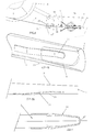
- a support means which is preferably made of a flat polyethylene sheath, the surface 34 of which is precut so as to form different sections 39 delimited by precuts 40 in half-moon shape, with a convex end and a concave end to distinguish the front of the rear during the step of threading the hose on said sheath.
- FIG. 12 represents a support means according to the invention constituted by a sheath made of material plastic having a multi-pleated type "accordion".
- This sheath has the shape of a surface 34 curved (folded) in half on itself, said surface 34 having an undulation parallel to the axis B of the curvature (fold) 35, said undulation being a succession of at least two vertices 36 and at least two hollow 37 of a sinusoid of amplitude and frequency essentially constant.
- the support means is a hollow sheath having a surface 34 slightly domed and an opening 38 over its entire length, said opening 38 being parallel to the axis B of the curvature 35. This opening 38 advantageously allows the withdrawal of the sheath when placing the hose on a cannula and removing of it during the embossing step.
- the plastic material of said sheath is chosen so as to offer a very good sliding coefficient, which allows easy removal hose.
- Figure 13 shows a device for production of a support means according to the invention.
- Such device includes in particular an extruder 20, a pulling track 21 to incorporate on a winder 22 the support means thus obtained.
- the device can also include a precut device 23 (precut sections).
- the hoses prior to their threading on the hollow tube, the hoses are assembled by an adhesive bonding process protein-type food to avoid loss of time when handling hose pieces when threading and to facilitate work.
- This glue can be composed of Carboxy-Methyl-Cellulose (CMC) or hydrolyzed starch.
- CMC Carboxy-Methyl-Cellulose
- This starch is preferably diluted in hot water (90 ° C) and used in high concentration (30 to 40% dry matter) giving a sticky effect by cooling.
- Such a product is, for example, the one sold under the brand THIBOLA 100® marketed by the company AMYLUM.
- the present invention therefore also relates to the hose consisting of hose sections including portions can possibly be superimposed.
- this hose may consist of sections of hose pre-glued with hydrolyzed starch or Carboxy-Methyl-Cellulose (CMC).
- CMC Carboxy-Methyl-Cellulose
Landscapes
- Life Sciences & Earth Sciences (AREA)
- Engineering & Computer Science (AREA)
- Wood Science & Technology (AREA)
- Zoology (AREA)
- Food Science & Technology (AREA)
- Rigid Pipes And Flexible Pipes (AREA)
Priority Applications (1)
| Application Number | Priority Date | Filing Date | Title |
|---|---|---|---|
| EP19980870079 EP0873689B1 (de) | 1997-04-15 | 1998-04-14 | Verfahren und Vorrichtung für die Vorbereitung von Därmen in einer Metzgerei |
Applications Claiming Priority (3)
| Application Number | Priority Date | Filing Date | Title |
|---|---|---|---|
| EP97870050 | 1997-04-15 | ||
| EP97870050A EP0872185A1 (de) | 1997-04-15 | 1997-04-15 | Verfahren und Vorrichtung für die Vorbereitung von Därmen in Metzgerei |
| EP19980870079 EP0873689B1 (de) | 1997-04-15 | 1998-04-14 | Verfahren und Vorrichtung für die Vorbereitung von Därmen in einer Metzgerei |
Publications (2)
| Publication Number | Publication Date |
|---|---|
| EP0873689A1 true EP0873689A1 (de) | 1998-10-28 |
| EP0873689B1 EP0873689B1 (de) | 2003-01-02 |
Family
ID=26148234
Family Applications (1)
| Application Number | Title | Priority Date | Filing Date |
|---|---|---|---|
| EP19980870079 Expired - Lifetime EP0873689B1 (de) | 1997-04-15 | 1998-04-14 | Verfahren und Vorrichtung für die Vorbereitung von Därmen in einer Metzgerei |
Country Status (1)
| Country | Link |
|---|---|
| EP (1) | EP0873689B1 (de) |
Cited By (1)
| Publication number | Priority date | Publication date | Assignee | Title |
|---|---|---|---|---|
| FR2855941A1 (fr) * | 2003-06-11 | 2004-12-17 | Boa Participations | Canule pour le plissage de boyau sur une gaine de plastique souple |
Families Citing this family (1)
| Publication number | Priority date | Publication date | Assignee | Title |
|---|---|---|---|---|
| NL2028349B1 (en) * | 2021-06-01 | 2022-12-13 | Van Hessen Holding B V | Intestinal tract part processing device and method |
Citations (10)
| Publication number | Priority date | Publication date | Assignee | Title |
|---|---|---|---|---|
| GB751514A (en) * | 1953-10-26 | 1956-06-27 | British Canadian Casings Ltd | "packaging of sausage casing gut" |
| FR1320867A (fr) | 1962-01-31 | 1963-03-15 | Tubophane | Procédé de conditionnement de boyaux naturels |
| CH407794A (fr) * | 1962-08-02 | 1966-02-15 | Sami S Svendsen Inc | Procédé de préparation d'une enveloppe naturelle de saucisse et dispositif pour sa mise en oeuvre |
| US3826853A (en) * | 1971-10-28 | 1974-07-30 | Oppenheimer Casing Co | Casing-carrier assembly and method |
| FR2462871A1 (fr) * | 1979-08-08 | 1981-02-20 | Remy Steffen | Procede pour la preparation des boyaux naturels en charcuterie, et dispositif pour sa mise en oeuvre |
| FR2539959A2 (fr) | 1979-08-08 | 1984-08-03 | Steffen Fils Ets A | Dispositif pour la preparation de boyaux naturels en charcuterie |
| US4713135A (en) * | 1985-09-09 | 1987-12-15 | Teepak, Inc. | Process for seaming coated cellulose webs |
| WO1990013226A1 (fr) * | 1989-05-03 | 1990-11-15 | Pierre Jonnard | Procede pour la preparation de boyaux naturels en charcuterie et le dispositif pour sa mise en ×uvre |
| FR2683978A1 (fr) * | 1991-11-26 | 1993-05-28 | Lamy Christian | Gaine souple pour le transfert de boyaux sur canule d'embossage. |
| FR2687546A1 (fr) * | 1992-02-24 | 1993-08-27 | Soussana | Procede pour la preparation, la liaison proteique, la conservation et l'utilisation de boyaux naturels. |
-
1998
- 1998-04-14 EP EP19980870079 patent/EP0873689B1/de not_active Expired - Lifetime
Patent Citations (10)
| Publication number | Priority date | Publication date | Assignee | Title |
|---|---|---|---|---|
| GB751514A (en) * | 1953-10-26 | 1956-06-27 | British Canadian Casings Ltd | "packaging of sausage casing gut" |
| FR1320867A (fr) | 1962-01-31 | 1963-03-15 | Tubophane | Procédé de conditionnement de boyaux naturels |
| CH407794A (fr) * | 1962-08-02 | 1966-02-15 | Sami S Svendsen Inc | Procédé de préparation d'une enveloppe naturelle de saucisse et dispositif pour sa mise en oeuvre |
| US3826853A (en) * | 1971-10-28 | 1974-07-30 | Oppenheimer Casing Co | Casing-carrier assembly and method |
| FR2462871A1 (fr) * | 1979-08-08 | 1981-02-20 | Remy Steffen | Procede pour la preparation des boyaux naturels en charcuterie, et dispositif pour sa mise en oeuvre |
| FR2539959A2 (fr) | 1979-08-08 | 1984-08-03 | Steffen Fils Ets A | Dispositif pour la preparation de boyaux naturels en charcuterie |
| US4713135A (en) * | 1985-09-09 | 1987-12-15 | Teepak, Inc. | Process for seaming coated cellulose webs |
| WO1990013226A1 (fr) * | 1989-05-03 | 1990-11-15 | Pierre Jonnard | Procede pour la preparation de boyaux naturels en charcuterie et le dispositif pour sa mise en ×uvre |
| FR2683978A1 (fr) * | 1991-11-26 | 1993-05-28 | Lamy Christian | Gaine souple pour le transfert de boyaux sur canule d'embossage. |
| FR2687546A1 (fr) * | 1992-02-24 | 1993-08-27 | Soussana | Procede pour la preparation, la liaison proteique, la conservation et l'utilisation de boyaux naturels. |
Cited By (1)
| Publication number | Priority date | Publication date | Assignee | Title |
|---|---|---|---|---|
| FR2855941A1 (fr) * | 2003-06-11 | 2004-12-17 | Boa Participations | Canule pour le plissage de boyau sur une gaine de plastique souple |
Also Published As
| Publication number | Publication date |
|---|---|
| EP0873689B1 (de) | 2003-01-02 |
Similar Documents
| Publication | Publication Date | Title |
|---|---|---|
| EP0662807B1 (de) | Vorrichtung zur implantation von haartransplantat mit kleinem durchmesser | |
| EP1052892B1 (de) | Verfahren zum ernten von von bäumen ausgeschiedenen produkten und erntetüte zur durchführung des verfahrens | |
| EP0123655A2 (de) | Automatischer Apparat zum Verpacken von Obst- und Gemüsebehältern mittels einer Netzumwicklung versehen mit Stützbändern und Etiketten | |
| CA2002338C (fr) | Procede de calibrage de mesure de la longueur et de conditionnement de troncons de boyaux utilises en charcuterie et dispositif pour sa mise en oeuvre | |
| EP0532391B1 (de) | Zange zum Zusammendrücken von Rohren, etwa einer Gasleitung | |
| EP3856271B1 (de) | Vorrichtung zum laden von haartransplantaten in ein transplantatimplantationsinstrument | |
| EP0873689B1 (de) | Verfahren und Vorrichtung für die Vorbereitung von Därmen in einer Metzgerei | |
| CA2214020C (fr) | Dispositif d'etirage automatique | |
| FR2688715A1 (fr) | Distributeur a main pour la pose d'un cordon de matiere souple sous un joint, procede de pose et application d'un tel cordon. | |
| FR2587593A1 (fr) | Appareillage et procede pour l'epluchage partiel du mais sweet corn frais. | |
| EP0872185A1 (de) | Verfahren und Vorrichtung für die Vorbereitung von Därmen in Metzgerei | |
| EP1052893B1 (de) | Vorrichtung zur durchführung von einschnitten in den baumstamm zum ernten von von bäumen ausgeschiedenen produkten | |
| CH616829A5 (en) | automatic machine for making a clove hitch with a cord around an object and use of the machine | |
| EP3909430A1 (de) | Vorrichtung zum portionieren von würsten | |
| EP1815743B1 (de) | Fremdkörperdetektierung in einer Vorrichtung zum Freischneiden des Enddarms von Schlachttieren | |
| EP0570253B1 (de) | Vorrichtung zum Halten, Verschliessen und eventuell Trennen von Wursthüllen | |
| WO1990007460A1 (fr) | Procede pour faciliter l'ouverture d'un emballage a film de matiere plastique, emballage obtenu a l'aide de ce procede et machine pour sa mise en ×uvre | |
| FR2539959A2 (fr) | Dispositif pour la preparation de boyaux naturels en charcuterie | |
| EP1151670B1 (de) | Verfahren zum Absaugen des Rückenmarks eines Viehkörpers | |
| FR2687546A1 (fr) | Procede pour la preparation, la liaison proteique, la conservation et l'utilisation de boyaux naturels. | |
| FR2864427A1 (fr) | Procede et installation pour preparer des tetes de salade | |
| FR2715531A1 (fr) | Dispositif de repiquage rapide de végétaux. | |
| EP4451845B1 (de) | Vorrichtung zur subkortikalen injektion einer substanz | |
| FR2682553A1 (fr) | Dispositif de repiquage rapide de vegetaux. | |
| CH627138A5 (de) |
Legal Events
| Date | Code | Title | Description |
|---|---|---|---|
| PUAI | Public reference made under article 153(3) epc to a published international application that has entered the european phase |
Free format text: ORIGINAL CODE: 0009012 |
|
| 17P | Request for examination filed |
Effective date: 19980511 |
|
| AK | Designated contracting states |
Kind code of ref document: A1 Designated state(s): DE ES FR GB |
|
| AX | Request for extension of the european patent |
Free format text: AL;LT;LV;MK;RO;SI |
|
| AKX | Designation fees paid | ||
| RBV | Designated contracting states (corrected) |
Designated state(s): DE ES FR GB |
|
| GRAG | Despatch of communication of intention to grant |
Free format text: ORIGINAL CODE: EPIDOS AGRA |
|
| 17Q | First examination report despatched |
Effective date: 20020123 |
|
| GRAG | Despatch of communication of intention to grant |
Free format text: ORIGINAL CODE: EPIDOS AGRA |
|
| GRAH | Despatch of communication of intention to grant a patent |
Free format text: ORIGINAL CODE: EPIDOS IGRA |
|
| GRAH | Despatch of communication of intention to grant a patent |
Free format text: ORIGINAL CODE: EPIDOS IGRA |
|
| GRAA | (expected) grant |
Free format text: ORIGINAL CODE: 0009210 |
|
| AK | Designated contracting states |
Kind code of ref document: B1 Designated state(s): DE ES FR GB |
|
| REG | Reference to a national code |
Ref country code: GB Ref legal event code: FG4D Free format text: 20030102:NOT ENGLISH |
|
| REF | Corresponds to: |
Ref document number: 69810377 Country of ref document: DE Date of ref document: 20030206 Kind code of ref document: P |
|
| PG25 | Lapsed in a contracting state [announced via postgrant information from national office to epo] |
Ref country code: DE Free format text: LAPSE BECAUSE OF FAILURE TO SUBMIT A TRANSLATION OF THE DESCRIPTION OR TO PAY THE FEE WITHIN THE PRESCRIBED TIME-LIMIT Effective date: 20030403 |
|
| PG25 | Lapsed in a contracting state [announced via postgrant information from national office to epo] |
Ref country code: GB Free format text: LAPSE BECAUSE OF NON-PAYMENT OF DUE FEES Effective date: 20030414 |
|
| GBT | Gb: translation of ep patent filed (gb section 77(6)(a)/1977) |
Effective date: 20030509 |
|
| PG25 | Lapsed in a contracting state [announced via postgrant information from national office to epo] |
Ref country code: ES Free format text: LAPSE BECAUSE OF FAILURE TO SUBMIT A TRANSLATION OF THE DESCRIPTION OR TO PAY THE FEE WITHIN THE PRESCRIBED TIME-LIMIT Effective date: 20030730 |
|
| PLBE | No opposition filed within time limit |
Free format text: ORIGINAL CODE: 0009261 |
|
| STAA | Information on the status of an ep patent application or granted ep patent |
Free format text: STATUS: NO OPPOSITION FILED WITHIN TIME LIMIT |
|
| GBPC | Gb: european patent ceased through non-payment of renewal fee |
Effective date: 20030414 |
|
| PG25 | Lapsed in a contracting state [announced via postgrant information from national office to epo] |
Ref country code: FR Free format text: LAPSE BECAUSE OF NON-PAYMENT OF DUE FEES Effective date: 20031231 |
|
| 26N | No opposition filed |
Effective date: 20031003 |
|
| REG | Reference to a national code |
Ref country code: FR Ref legal event code: ST |