EP0873703A2 - Système d'étagères - Google Patents
Système d'étagères Download PDFInfo
- Publication number
- EP0873703A2 EP0873703A2 EP98105053A EP98105053A EP0873703A2 EP 0873703 A2 EP0873703 A2 EP 0873703A2 EP 98105053 A EP98105053 A EP 98105053A EP 98105053 A EP98105053 A EP 98105053A EP 0873703 A2 EP0873703 A2 EP 0873703A2
- Authority
- EP
- European Patent Office
- Prior art keywords
- shelf
- recesses
- column
- perforation
- jump
- Prior art date
- Legal status (The legal status is an assumption and is not a legal conclusion. Google has not performed a legal analysis and makes no representation as to the accuracy of the status listed.)
- Withdrawn
Links
Images


Classifications
-
- A—HUMAN NECESSITIES
- A47—FURNITURE; DOMESTIC ARTICLES OR APPLIANCES; COFFEE MILLS; SPICE MILLS; SUCTION CLEANERS IN GENERAL
- A47B—TABLES; DESKS; OFFICE FURNITURE; CABINETS; DRAWERS; GENERAL DETAILS OF FURNITURE
- A47B57/00—Cabinets, racks or shelf units, characterised by features for adjusting shelves or partitions
- A47B57/30—Cabinets, racks or shelf units, characterised by features for adjusting shelves or partitions with means for adjusting the height of detachable shelf supports
Definitions
- the invention relates to a shelf system with a shelf column, a perforation with periodically spaced Has recesses for attaching shelf elements.
- the shelf columns generally have a perforated grid on where between adjacent cutouts a 32 mm jump is provided.
- countries are predominantly shelf columns with one 50 mm jump used.
- These different shelf standards with the perforation grid make it necessary that the associated merchandise supports and other accessories that are attached to should be hung on the shelf columns with their hooks specially tailored to the different jump distances are. This has the consequence that the Anglo-Saxon countries and the non-Anglo-Saxon countries used Shelf systems are not compatible with each other.
- a Shelf manufacturer that is present on the entire European market must be at least two different shelving systems develop and manufacture what is mainly under from the cost point of view as extremely unsatisfactory.
- the shelving columns used in shop fitting for retail shelving systems are used, generally have two perforation forms on. So the shelf columns are often with double slot cutouts equipped as shown in Figure 1A, the enable hooking-in shelf elements next to each other, all the more shelf units over a shelf column to be able to connect with each other.
- This double slotted hole it also enables e.g. in the area below Attach foot parts with double hooks when the shelving system should be designed as a gondola to ensure high rigidity to ensure the rack structure.
- Double slots in the shelf column is, however, production-related relatively complex. In addition, often also designed due to the attachment of shelf elements to the shelf column the narrow slot formation difficult.
- the object of the present invention is to achieve the above Avoid disadvantages of conventional shelving systems and to provide a shelving system that stands out is characterized by high flexibility and compatibility and can be produced inexpensively.
- the Shelf column a perforation with substantially periodically spaced Cutouts for attaching shelf elements on, the recesses are designed so that a jump between adjacent cutouts of 33 1/3 mm and between every first and fourth recess of 100 mm with each with a tolerance of ⁇ 2 mm.
- This shelving system connects hence the shelf standards of both Anglo-Saxon countries as well as the non-Anglo-Saxon countries.
- the 100th mm jump between the first and fourth recess allows equipping the shelf system with numerous shelf elements, which can also be attached to shelf columns with 50 mm jumps leave because e.g. Consoles that carry heavy loads, in the shelving system with 50 mm jump, their two hooks at 100 mm intervals have sufficient stability in the mounted To achieve condition.
- the periodically spaced recesses of the perforation in the Shelf column preferably a length of 20 mm. This length on the one hand ensures that the hooks on the product carriers easy to install, and on the other hand for one sufficient rigidity of the shelf column to carry high loads by the remaining distance between two neighboring ones Recesses.
- the recesses of the perforation in the shelf column essentially rectangular with one in the middle on the underside Shaped cones.
- This hole shape has the same advantages like the H-hole, i.e. a simple insertion of the Hook due to the sufficient given by the large hole shape Game as well as the possibility of a stable attachment of two product carriers next to each other.
- the one below upwardly projecting pin ensures that the product carriers are suspended due to their own weight or load from goods for sufficient lateral stability so that on the upper pin can be dispensed with. Omitting the top Pin also enables simplified assembly, because their hooks are particularly easy in the perforation have it introduced.
- the perforation shows only A spigot also has advantages in terms of production, since only six instead of eight corners have to be punched out, which is one simpler and therefore less prone to damage die cutting enables.
- the shelf system in the lower area of the shelf column has two cutouts for attaching shelf base parts that are essentially are rectangular in shape and on the top have attached pegs.
- the arranged at the top Pins prevent the shelf columns from tilting, if these are suspended from the foot parts in a self-supporting manner.
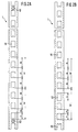
- FIGS. 2A and 2B show the shelf column according to the invention in two different embodiments.
- the shelf column 1 as a wall rail with a U-profile designed that on the front a perforated grid with periodic spaced recesses 11.
- These recesses 11 are substantially rectangular, wherein a short spigot in the center on the underside protrudes.
- the recesses are preferably centered in the Column with a width of 14 mm. This width dimensioning on the one hand ensures adequate Rigidity of the shelf column and on the other hand enough space around Insert two hooks side by side into the recess to be able to.
- the peg in the middle on the underside preferably protrudes at least 3 mm into the recess lateral sliding of those located in the recesses To prevent hooks reliably.
- the recesses 11 are periodic in the shelf column 1 with a jump between two adjacent cutouts from 33 1/3 mm (a) taking into account a manufacturing tolerance spaced ⁇ 2 mm apart. This 33 1/3 mm jump will continue within the stated manufacturing tolerance of a 100 mm jump (b) superimposed.
- the cutouts 11 are still preferred on the shelf column formed with a length of 20 mm (c) and spaced 13.3 mm (d).
- FIG 2B shows a shelf column 1 according to the invention a closed column profile, e.g. as a support can be used with a shelf nacelle.
- a closed column profile e.g. as a support can be used with a shelf nacelle.
- the pin in contrast to the design of the remaining recesses from the top protrude into the recess.
- These recesses 13 are used to attach foot parts to the shelf column, such as the side view shown in Figure 3 shows.
- the foot parts 2 have two according to the distance between the Double hooks spaced apart from two recesses 13 on the shelf column to engage in these recesses.
- Through the overhead pin in the recesses 13 is reliable sufficient lateral stability when placed on the foot parts Shelf columns also reached when carrying heavy loads.
- opposite the remaining recesses may be larger, preferably with a length of 26 mm (e), also for foot parts with larger ones To be able to attach hooks.
- the foot parts 2 are preferred provided with two foot plates 21 that are height adjustable are designed to align the shelves vertically and horizontally to be able to.
- the shelf columns according to the invention can be, how is shown in Figures 3 and 4, with a variety of Equip accessories. So you can on the shelf column Standard console 3 with two or more hooks, which too can be designed as double hooks, are hooked on which shelves 4 are placed, which in turn with a Price rail 5 can be provided.
- the shelf columns according to the invention in a simple manner back wall elements 6 with the hooks protruding to the rear, whose hook spacing, as shown in FIG. 3, is preferably 100 mm, which ensures simple and reliable installation.
- the shelf column according to the invention enables a versatile Modular system that meets all requirements in the shelf area is justified because of the 33 1/3 mm jump and the 100 mm jump maximum compatibility in the perforation grid to almost all known shelving systems is manufactured.
- the chosen one Punching shape also ensures a high degree of flexibility and a quick and easy installation and conversion without Draw restrictions on the shelf load.
Landscapes
- Assembled Shelves (AREA)
- Warehouses Or Storage Devices (AREA)
- Vehicle Body Suspensions (AREA)
- Devices That Are Associated With Refrigeration Equipment (AREA)
Applications Claiming Priority (2)
| Application Number | Priority Date | Filing Date | Title |
|---|---|---|---|
| DE29705604U DE29705604U1 (de) | 1997-03-27 | 1997-03-27 | Regalsystem |
| DE29705604U | 1997-03-27 |
Publications (2)
| Publication Number | Publication Date |
|---|---|
| EP0873703A2 true EP0873703A2 (fr) | 1998-10-28 |
| EP0873703A3 EP0873703A3 (fr) | 2001-05-16 |
Family
ID=8038159
Family Applications (1)
| Application Number | Title | Priority Date | Filing Date |
|---|---|---|---|
| EP98105053A Withdrawn EP0873703A3 (fr) | 1997-03-27 | 1998-03-19 | Système d'étagères |
Country Status (5)
| Country | Link |
|---|---|
| EP (1) | EP0873703A3 (fr) |
| DE (1) | DE29705604U1 (fr) |
| NO (1) | NO981319L (fr) |
| PL (1) | PL187739B1 (fr) |
| TR (1) | TR199800566A2 (fr) |
Cited By (5)
| Publication number | Priority date | Publication date | Assignee | Title |
|---|---|---|---|---|
| WO2005064110A1 (fr) | 2003-12-23 | 2005-07-14 | Tegometall (International) Ag | Armoire |
| FR2953697A1 (fr) * | 2009-12-15 | 2011-06-17 | Mobil M | Etagere |
| DE202012102741U1 (de) | 2012-07-20 | 2013-10-22 | Tegometall International Ag | Rückwandprofil für ein modulares Regalsystem |
| EP2671473A1 (fr) | 2012-06-08 | 2013-12-11 | Holding Stamhuis B.V. | Procédé pour le pré-assemblage et le placement d'unités de rayonnage et ensemble d'unités de rayonnage interconnectées |
| DE202024107273U1 (de) | 2024-12-13 | 2026-04-30 | Wanzl GmbH & Co. KGaA | Regalsystem |
Families Citing this family (1)
| Publication number | Priority date | Publication date | Assignee | Title |
|---|---|---|---|---|
| DE20104590U1 (de) * | 2001-03-14 | 2002-07-25 | Friedrich, Gerhard, 63571 Gelnhausen | Regal |
Family Cites Families (6)
| Publication number | Priority date | Publication date | Assignee | Title |
|---|---|---|---|---|
| US3057483A (en) * | 1960-08-01 | 1962-10-09 | Derman Sam | Strip and bracket units for supporting shelves and other articles |
| GB1325399A (en) * | 1971-12-14 | 1973-08-01 | Metallwarenfabrik Karl Harr | Sales racks |
| FR2254936A5 (en) * | 1973-12-12 | 1975-07-11 | Peugeot Cycles | Dual purpose upright post for shelving - has openings locating single or double brackets in two reversed post positions |
| DE3028552A1 (de) * | 1980-07-28 | 1982-02-25 | Tegometall Rudolf Bohnacker, 7482 Krauchenwies | Winkelfoermige trageinheit fuer stehende regale |
| GB9103158D0 (en) * | 1991-02-14 | 1991-04-03 | Nuttall Shelving Systems Limit | Joints for use in racking or shelving systems |
| DE29605974U1 (de) * | 1996-03-30 | 1996-06-05 | abstron Metall- + Werkzeugbau GmbH, 99625 Kölleda | Variables Warenregal |
-
1997
- 1997-03-27 DE DE29705604U patent/DE29705604U1/de not_active Expired - Lifetime
-
1998
- 1998-03-19 EP EP98105053A patent/EP0873703A3/fr not_active Withdrawn
- 1998-03-23 PL PL98325497A patent/PL187739B1/pl not_active IP Right Cessation
- 1998-03-24 NO NO981319A patent/NO981319L/no not_active Application Discontinuation
- 1998-03-27 TR TR1998/00566A patent/TR199800566A2/xx unknown
Non-Patent Citations (1)
| Title |
|---|
| None |
Cited By (5)
| Publication number | Priority date | Publication date | Assignee | Title |
|---|---|---|---|---|
| WO2005064110A1 (fr) | 2003-12-23 | 2005-07-14 | Tegometall (International) Ag | Armoire |
| FR2953697A1 (fr) * | 2009-12-15 | 2011-06-17 | Mobil M | Etagere |
| EP2671473A1 (fr) | 2012-06-08 | 2013-12-11 | Holding Stamhuis B.V. | Procédé pour le pré-assemblage et le placement d'unités de rayonnage et ensemble d'unités de rayonnage interconnectées |
| DE202012102741U1 (de) | 2012-07-20 | 2013-10-22 | Tegometall International Ag | Rückwandprofil für ein modulares Regalsystem |
| DE202024107273U1 (de) | 2024-12-13 | 2026-04-30 | Wanzl GmbH & Co. KGaA | Regalsystem |
Also Published As
| Publication number | Publication date |
|---|---|
| TR199800566A2 (xx) | 1998-10-21 |
| PL187739B1 (pl) | 2004-09-30 |
| NO981319L (no) | 1998-09-28 |
| NO981319D0 (no) | 1998-03-24 |
| PL325497A1 (en) | 1998-09-28 |
| DE29705604U1 (de) | 1998-07-30 |
| EP0873703A3 (fr) | 2001-05-16 |
Similar Documents
| Publication | Publication Date | Title |
|---|---|---|
| DE69226008T2 (de) | Modulares Regal mit Schnellwechselsystem | |
| DE69326847T2 (de) | Tragärmezusammensetzung für regale | |
| EP2934240B1 (fr) | Système d'étagères | |
| DE60221445T2 (de) | System für das abnehmbare aufhängen von regalen, schubladen o.ä. | |
| DE3832537C2 (fr) | ||
| EP0644338A1 (fr) | Jeu de construction pour meubles | |
| DE1554247C3 (de) | Tragkonstruktion für Regale | |
| DE29705604U1 (de) | Regalsystem | |
| EP3420857A1 (fr) | Appui d'étagère, dispositif d'appui d'étagère, système d'étagères et espace de rangement pour un système d'étagères | |
| EP0908120B1 (fr) | Etagère | |
| DE69206437T2 (de) | Aus kastenförmigen Elementen aufgebauter Sockel für Regalmöbel aus Metall. | |
| EP2062503B1 (fr) | Système d'étagère | |
| DE3878214T2 (de) | Metallisches regal. | |
| DE29917925U1 (de) | Regalaufbau | |
| DE3148504A1 (de) | Staender fuer ein regalsystem | |
| DE3214992C3 (de) | Schublade mit Einteilungsmitteln | |
| DE29910247U1 (de) | Warenaufhängungs- und Informationsanordnung für ein vertikale Holme aufweisendes Regalsystem | |
| EP0427914A1 (fr) | Etagère | |
| DE102022101705A1 (de) | Blumenkasten | |
| DE10112467A1 (de) | Regalständer und damit hergestelltes Warenregal | |
| DE19922510A1 (de) | Wandregal- und Warenpräsentationssystem | |
| DE8110056U1 (de) | Displaystaender | |
| EP0698356A1 (fr) | Cadre de support pour rayonnages | |
| DE10306537A1 (de) | System zur Präsentation von Gegenständen | |
| DE29717301U1 (de) | Vorrichtung zur Vertikal-Präsentation von Langgutwaren |
Legal Events
| Date | Code | Title | Description |
|---|---|---|---|
| PUAI | Public reference made under article 153(3) epc to a published international application that has entered the european phase |
Free format text: ORIGINAL CODE: 0009012 |
|
| AK | Designated contracting states |
Kind code of ref document: A2 Designated state(s): AT BE CH DE DK ES FI FR GB GR IE IT LI LU MC NL PT SE |
|
| AX | Request for extension of the european patent |
Free format text: AL;LT;LV;MK;RO;SI |
|
| PUAL | Search report despatched |
Free format text: ORIGINAL CODE: 0009013 |
|
| AK | Designated contracting states |
Kind code of ref document: A3 Designated state(s): AT BE CH DE DK ES FI FR GB GR IE IT LI LU MC NL PT SE |
|
| AX | Request for extension of the european patent |
Free format text: AL;LT;LV;MK;RO;SI |
|
| RIC1 | Information provided on ipc code assigned before grant |
Free format text: 7A 47B 57/42 A, 7A 47B 57/30 B, 7A 47B 96/14 B, 7A 47B 91/00 B |
|
| AKX | Designation fees paid | ||
| REG | Reference to a national code |
Ref country code: DE Ref legal event code: 8566 |
|
| STAA | Information on the status of an ep patent application or granted ep patent |
Free format text: STATUS: THE APPLICATION IS DEEMED TO BE WITHDRAWN |
|
| 18D | Application deemed to be withdrawn |
Effective date: 20011001 |