EP0873717A2 - Ultraschall-Messvorrichtung zur Bestimmung der Dichte und der Beschaffenheit von Knochengewebe - Google Patents
Ultraschall-Messvorrichtung zur Bestimmung der Dichte und der Beschaffenheit von Knochengewebe Download PDFInfo
- Publication number
- EP0873717A2 EP0873717A2 EP98107423A EP98107423A EP0873717A2 EP 0873717 A2 EP0873717 A2 EP 0873717A2 EP 98107423 A EP98107423 A EP 98107423A EP 98107423 A EP98107423 A EP 98107423A EP 0873717 A2 EP0873717 A2 EP 0873717A2
- Authority
- EP
- European Patent Office
- Prior art keywords
- waveform
- signal
- peaks
- ultrasonic
- bone
- Prior art date
- Legal status (The legal status is an assumption and is not a legal conclusion. Google has not performed a legal analysis and makes no representation as to the accuracy of the status listed.)
- Withdrawn
Links
- 230000037182 bone density Effects 0.000 title claims description 11
- 210000000988 bone and bone Anatomy 0.000 claims abstract description 51
- 210000003275 diaphysis Anatomy 0.000 claims abstract description 14
- 230000001054 cortical effect Effects 0.000 claims abstract description 13
- 239000007787 solid Substances 0.000 claims abstract description 5
- 238000000034 method Methods 0.000 claims description 16
- 238000004458 analytical method Methods 0.000 claims description 8
- 230000004044 response Effects 0.000 claims description 3
- 238000005259 measurement Methods 0.000 description 10
- 230000000694 effects Effects 0.000 description 4
- 238000003909 pattern recognition Methods 0.000 description 4
- 230000000737 periodic effect Effects 0.000 description 3
- 238000010586 diagram Methods 0.000 description 2
- 208000020084 Bone disease Diseases 0.000 description 1
- 208000001132 Osteoporosis Diseases 0.000 description 1
- 206010036590 Premature baby Diseases 0.000 description 1
- 230000003321 amplification Effects 0.000 description 1
- 210000003484 anatomy Anatomy 0.000 description 1
- 230000009286 beneficial effect Effects 0.000 description 1
- 230000005540 biological transmission Effects 0.000 description 1
- 239000003086 colorant Substances 0.000 description 1
- 238000005115 demineralization Methods 0.000 description 1
- 230000002328 demineralizing effect Effects 0.000 description 1
- 201000010099 disease Diseases 0.000 description 1
- 208000037265 diseases, disorders, signs and symptoms Diseases 0.000 description 1
- 210000002745 epiphysis Anatomy 0.000 description 1
- 238000003199 nucleic acid amplification method Methods 0.000 description 1
- 230000009103 reabsorption Effects 0.000 description 1
- 206010039073 rheumatoid arthritis Diseases 0.000 description 1
- 230000001360 synchronised effect Effects 0.000 description 1
- 210000000689 upper leg Anatomy 0.000 description 1
Images
Classifications
-
- A—HUMAN NECESSITIES
- A61—MEDICAL OR VETERINARY SCIENCE; HYGIENE
- A61B—DIAGNOSIS; SURGERY; IDENTIFICATION
- A61B8/00—Diagnosis using ultrasonic, sonic or infrasonic waves
- A61B8/08—Clinical applications
- A61B8/0875—Clinical applications for diagnosis of bone
Definitions
- the present invention relates to an ultrasonic measuring device for determining bone density and structure.
- Electronic devices for examining bone tissue and structure comprise an ultrasonic transducer for feeding pulses into a bone segment for examination (e.g. a finger); a receiver for picking up the pulses that have traveled through the bone segment; and processing circuits for representing the waveform and, given the distance between the transducer and the receiver, calculating the speed of the ultrasonic signal through the bone segment.
- a bone segment for examination e.g. a finger
- processing circuits for representing the waveform and, given the distance between the transducer and the receiver, calculating the speed of the ultrasonic signal through the bone segment.
- known devices compare the measured speed value with a reference value to determine a variation in bone structure and density, which normally indicates demineralization of the bone tissue (caused, for example, by osteoporosis).
- the waveform is also examined by a skilled technician to obtain information, albeit approximate and at times ambiguous, concerning the characteristics of the bone segment.
- known devices fail to provide for precise analysis closely related to the characteristics of the bone tissue, and interpretation is further complicated in the event the bone segment comprises a distal portion.
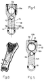
- the distal portion of a bone (Figure 8) is known to comprise a substantially solid first end portion A (metaphysis) defined by a shell of thin cortical bone containing mainly bone trabeculae; and a more proximal, substantially tubular second portion B (diaphysis) comprising an outer tubular (cortical) portion defining an inner canal containing few bone trabeculae, which, in adults, are reabsorbed to hollow out the canal of the second portion.
- metal end portion A metalaphysis
- second portion B diaphysis
- a known device measuring the above distal portion produces a waveform and calculates the ultrasonic speed of an ultrasonic signal traveling indifferently through the first and second portions, which, as stated, have entirely different structures.
- certain bone diseases however, have a widely differing effect on the first and second portions, a separate analysis of the structural characteristics of the first (metaphysis) and second (diaphysis) portions would be extremely beneficial.
- an ultrasonic measuring device for determining bone density and structure, as claimed in Claim 1.
- the present invention also relates to a method of determining bone density and structure, as claimed in Claim 12.
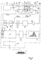
- Number 1 in Figure 1 indicates as a whole an electronic ultrasonic measuring device for determining bone density and structure, and comprising a central unit 3 housed in a parallelepiped casing (not shown), connected to a positioning gage 5 (shown schematically in Figure 1), and having a keyboard 7 and a video terminal 9.
- the central unit comprises a signal generating circuit 11 for generating a periodic signal of given frequency and highly constant amplitude, and which, in the example embodiment shown, generates a periodic pulse signal of 0.8 to 15 MHz frequency, e.g. 1.25 MHz.
- the output of circuit 11 communicates with the input 13a of a demultiplexer circuit 13, which has two outputs 13b, 13c communicating respectively with a first and a second piezoelectric transducer 16, 17 carried by positioning gage 5 and each for generating, in response to the periodic pulse signal at the input, an ultrasonic signal which is fed to a portion 20 of the human body (shown schematically) placed inside gage 5 (as described later on).
- Transducers 16 and 17 are separated by a constant distance h, so that the ultrasonic signals generated by them travel along straight parallel propagation paths S1, S2 also separated by distance h, and may generate synchronized ultrasonic signals or ultrasonic pulses at different instants.
- First transducer 16 is connected to a first ultrasonic receiver 22 carried by gage 5 and facing first transducer 16 along path S1; second transducer 17 is connected to a second ultrasonic receiver 23 carried by gage 5 and facing second transducer 17 along path S2; and the facing respectively emitting and receiving surfaces of transducer 16 and receiver 22 and transducer 17 and receiver 23 are separated by a manually adjustable distance D. More specifically, distance D is measured by a position transducer 24 carried by positioning gage 5 and for generating a signal Dpos proportional to the measured value of distance D.
- First and second ultrasonic receivers 22, 23 communicate respectively at the output with a first and a second input 25b, 25c of a multiplexer circuit 25, the output 25a of which communicates with the input of a signal amplifier 28; and demultiplexer and multiplexer circuits 13 and 25 are controlled synchronously by a remote signal SYNC, so as to connect input 13a to output 13b and input 25b to output 25a, or to connect input 13a to output 13c and input 25c to output 25a.
- the output of signal amplifier 28 is connected to the input of a filter 30 (in particular, a low-pass filter), the output of which is connected to a signal processing circuit 32 (e.g.
- a multiplexer circuit 34 the output of which is connected to an analog-digital converting circuit 36.
- Multiplexer circuit 34 also has other inputs, one of which is supplied with position signal Dpos from gage 5; and the output of converting circuit 36 communicates with an input of a microprocessor processing and control circuit 40, which, among other things, controls demultiplexer circuit 13, multiplexer circuit 25 and multiplexer circuit 34, communicates with keyboard 7 via an interface circuit 42, and supplies control signals to a video board 44 driving video terminal 9.
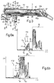
- number 5 indicates as a whole ultrasonic gage 5, which comprises a first outer tubular body 50 connected telescopically to a second inner tubular body 51 coaxial with, and sliding with respect to, body 5 along an axis 52.
- First tubular body 50 has a first threaded free end 50a from which extends a first radial appendix 53 comprising a substantially parallelepiped base portion 53a with a threaded through hole 54 engaged by end 50a, and a straight portion 53b extending radially from base portion 53a.
- the free end of straight portion 53b has a through hole 55 engaged by a parallelepiped container housing first and second piezoelectric transducers 16, 17.
- Second tubular body 51 projects from body 50 and terminates with an end portion 51a supporting a second radial appendix 56 facing first appendix 53, and which comprises a substantially parallelepiped base portion 56a integral with end 51a, and a straight portion 56b extending radially from base portion 56a.
- the free end of straight portion 56b has a through hole 57 engaged by a cylindrical tubular container housing first and second ultrasonic receivers 22, 23.
- Second appendix 56 has a pair of through holes 58 extending close to an end edge of hole 57. More specifically, through holes 58 are located along an axis d1 perpendicular to the central longitudinal axis d2 of the appendix, and are symmetrical with axis d2.
- Each hole 58 houses an end portion of a cylindrical rod 60 extending between second and first appendixes 56, 53 and parallel to axis 52.
- Rods 60 therefore extend parallel to each other, are separated by a distance substantially equal to the distance, measured along axis d1, between holes 58, and define a locating element for correctly positioning (as described later on) a portion of the human body, in particular a finger, with respect to appendixes 53, 56, transducers 16, 17, and receivers 22, 23.
- the portion of the human body used for measurement purposes may comprise the distal femur, in the case of measurements performed on newborn or premature babies, and the epiphysis of the index finger in the case of measurements for determining diseases relating to rheumatoid arthritis. Whichever the case, the examination region comprises a metaphysis and a diaphysis portion.
- Holes 58 are so located that, when a finger is placed in the gage with a portion contacting both rods 60, an end bone portion of the finger is centered between transducers 16, 17 and receivers 22, 23.
- Gage 5 also comprises a device 61 for manually adjusting the distance D between transducers 16, 17 and receivers 22, 23.
- Device 61 comprises a rectangular blade 62 having a first free end 62a fixed stably to base portion 56a by means of screws, and a second free end 62b housed inside a rectangular groove 64 formed in base portion 53a.
- Blade 62 is slightly arc-shaped and presses on the bottom portion (not shown) of groove 64.
- Blade 62 also comprises a toothed mid portion 62c; and gage 5 comprises a tube 65 carried by body 50 and extending along an axis 66 parallel to axis 52. More specifically, tube 65 comprises a first end portion 65a carried by an end body 67 integral with a second end 50b of tubular body 50; an intermediate portion engaging a through hole 68 formed in appendix 53 and coaxial with axis 66; and a second end portion 65b adjacent to portion 51a of body 51, and which terminates with an opening closed by a plug 69 with a hole, and also engages a through hole 70 formed in appendix 56 and coaxial with axis 66.
- Tube 65 houses the cables supplying the energizing signal to transducers 16, 17, and the cables supplying the output signal to receivers 22, 23.
- Transducer 24 is defined by a linear potentiometer (not shown) housed inside, and for determining the relative position of, tubular bodies 50, 51 to measure distance D and generate position signal Dpos.
- An elastic element 80 (shown schematically) is interposed between bodies 50 and 51 to retain body 51 inside body 50 and push appendixes 53, 56 into contact with each other.
- the elastic force exerted by elastic element 80 may be adjustable.
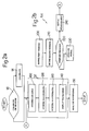
- a block 90 enquires - the enquiry being displayed on video terminal 9 - whether device 1 is to be calibrated or a measuring session performed.
- block 90 goes on to a block 91, which starts the device calibration procedures in known manner. Conversely, block 90 goes on to a block 92, which performs a series of bone density and structure measuring operations. Once the device is calibrated, block 91 also goes on to block 92.
- appendixes 53 and 56 are parted manually using device 61 in opposition to elastic element 80.
- a first phalanx of one finger is then placed between transducers 16, 17 and receivers 22, 23, with the back of the phalanx contacting both rods 60.
- the axis of the finger is roughly perpendicular to axis 52 of the gage and to propagation paths S1 and S2, and the distal metaphysis of the phalanx is located between transducers 16, 17 and receivers 22, 23.
- the distal portion of the phalanx is known to comprise a substantially solid first end portion A (metaphysis) defined by a shell of thin cortical bone containing mainly bone trabeculae; and a more proximal, substantially tubular second portion B (diaphysis) comprising an outer tubular (cortical) portion defining an inner canal containing few bone trabeculae.
- first end portion A metal containing mainly bone trabeculae
- diaphysis substantially tubular second portion B comprising an outer tubular (cortical) portion defining an inner canal containing few bone trabeculae.
- the canal of portion B is known to be hollowed out by reabsorption of the bone trabeculae, and portion A is also hollowed out later, though never completely.
- propagation path S1 therefore extends through first portion A, and propagation path S2 through second portion B adjacent to portion A, i.e. the ultrasonic signal produced by transducer 16 travels mainly through the bone portion rich in trabeculae, while the ultrasonic signal produced by transducer 17 travels mainly through the inner canal surrounded by the cortical portion.
- Positioning the finger as described above provides, for each measurement, for correctly positioning portions A and B of the bone tissue with respect to transducers 16, 17.
- block 92 comprises a block 100, which provides for automatically acquiring distance D between transducers 16, 17 and receivers 22, 23. More specifically, the (analog) signal generated by potentiometer 24 is supplied, via multiplexer 34, to converter 36, which supplies microprocessor 40 with the digital value of distance D, which may be displayed on video 9 and used later for calculating other parameters.
- Block 100 is followed by a first measuring block 120, which acquires and displays on video 9 the waveform of the ultrasonic signal received by receiver 22.
- block 120 of microprocessor circuit 40 sets demultiplexer 13 and multiplexer 25 to a first position in which input 13a is connected to output 13b, and input 25b to output 25a; the alternating signal supplied by circuit 11 to transducer 16 produces a stream of ultrasonic waves along path S1 through portion A (the trabecular portion) of the bone to receiver 22; and the signal generated by receiver 22 is voltage-amplified by amplifier 28, filtered by filter 30, possibly processed by circuit 32, digitized by converter 36, and supplied to microprocessor circuit 40.
- Microprocessor circuit 40 effects (in known manner) a cartesian reconstruction ( Figure 6a) of the waveform FO1 of the ultrasonic signal received by receiver 22, wherein the X axis represents a time scale and the Y axis an amplitude scale, with time and amplitude values increasing outwards of the origin.
- the cartesian representation of waveform FO1 of the signal through distal metaphysis portion A has been found by the inventors to comprise a first portion I (shown enclosed in a rectangle) in turn comprising a number of successive peaks Ptr (normally three or four); a second portion II (shown enclosed in a rectangle) adjacent to the first portion and in turn comprising a small number of peaks of substantially negligible amplitude; and a third portion III (shown enclosed in a rectangle) adjacent to second portion II and in turn comprising a large number of peaks generally of greater amplitude than those of first portion I.
- the first portion I of waveform FO1 is assumed by the inventors to relate to the signal portion through the trabecular portion of the bone, and second portion II of the waveform to the signal portion through the cortical portion of the bone.
- first portion I comprises a large amount of energy (significant peaks Ptr); second portion II comprises very little energy (almost negligible peaks); and third portion III mainly comprises noise caused by bouncing and reflection of the energizing signal.
- Waveform FO1 as illustrated is memorized (digitized) by block 120 in a buffer memory 41 communicating with microprocessor circuit 40.
- First measuring block 120 is followed by a second measuring block 130, which acquires and displays on video 9 the waveform FO2 ( Figure 6b) of the ultrasonic signal received by receiver 23.
- microprocessor circuit 40 sets demultiplexer 13 and multiplexer 25 to a second position in which input 13a is connected to output 13c, and input 25c to output 25a; the alternating signal supplied by circuit 11 to transducer 17 produces a stream of ultrasonic waves along path S2 through portion B (the cortical portion and canal) of the bone to receiver 23; and the signal generated by receiver 23 is voltage-amplified by amplifier 28, filtered by filter 30, possibly processed by circuit 32, digitized by converter 36, and supplied to microprocessor circuit 40.
- Microprocessor circuit 40 effects (in known manner) a cartesian reconstruction of the waveform of the ultrasonic signal received by receiver 23, as described above for the signal received by receiver 22.
- the cartesian representation ( Figure 6b) of waveform FO2 of the signal through diaphysis portion B has been found by the inventors to comprise a first portion I' (shown enclosed in a rectangle) in turn comprising a small number of successive peaks of negligible amplitude; a second portion II' (shown enclosed in a rectangle) adjacent to the first portion and in turn comprising a number of peaks Pco; and a third portion III' (shown enclosed in a rectangle) adjacent to second portion II' and in turn comprising a large number of peaks generally of greater amplitude than those of the second portion.
- the first portion I' of waveform FO2 is assumed by the inventors to relate to the signal portion through the trabecular portion of the bone, and second portion II' of the waveform to the signal portion through the cortical portion of the bone.
- second portion II' comprises a large amount of energy (significant peaks Pco); first portion I' comprises very little energy (almost negligible peaks); and third portion III' mainly comprises noise caused by bouncing and reflection of the energizing signal.
- Waveform FO2 as illustrated is memorized by block 130 in buffer memory 41.
- Block 130 is followed by a block 140, which provides for displaying the acquired, memorized waveforms FO1 and FO2. More specifically, block 140 may:
- the present invention also provides for performing a series of automatic operations on waveforms FO1 and FO2 (block 150 following block 140).
- Block 150 comprises a first block 200, which subjects waveform FO1 to a characteristic-pattern recognition process to define a window F1 (e.g. a rectangle) enclosing first portion I of waveform FO1, and to determine the time limits tI1 and tI2 of window F1 (defined as the points at which the window intersects the time axis).
- the pattern recognition process may be performed in known manner by determining, in first waveform FO1, the first group of adjacent peaks having, on either side, signal portions of a given substantially zero amplitude.
- Block 200 is followed by a block 210, which subjects waveform FO2 to a characteristic-pattern recognition process to define a window F2 (e.g. a rectangle) enclosing second portion II' of waveform FO2, and to determine the time limits tII1 and tII2 of window F2 (defined as the points at which the window intersects the time axis).
- the pattern recognition process may be performed in known manner by determining, in second waveform FO2, the first group of adjacent peaks having, on one side, signal portions of a given substantially lower amplitude, and, on the other side, signal portions of a higher amplitude.
- Block 210 is followed by a block 220, which compares windows F1 and F2 to automatically check the measurements are correct. More specifically, if first window F1 is substantially adjacent to second window F2 in a cartesian system having the same origin as the cartesian systems of waveforms FO1 and FO2, i.e. if tI2 is substantially equal to tII1, the measurement is considered correct, and block 220 goes on to a block 230. Conversely, block 220 goes on to a block 240, which displays a repeat-measurement message on the video, and then goes back to block 92 to perform another measuring cycle.
- Block 230 performs a series of operations on the portions of waveforms FO1, FO2 in windows F1 and/or F2 to obtain information concerning bone density and structure, and whereby block 230 calculates (relative to windows F1 and F2):
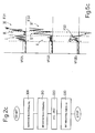
- Figure 2c shows a series of "clean-up" operations of waveforms FO1 and FO2, performed for example to improve the effectiveness of block 150, and which may conveniently be performed prior to the block 150 waveform analysis.
- the waveform "clean-up" operations comprise a first block 300, which retrieves digitized waveform FO1 from memory 41, and is followed by a block 310, which retrieves from memory 41 digitized waveform FO2.
- Block 310 is followed by a block 320 in which, for each X-axis value "i" in the reference system of waveform FO1, the corresponding amplitude value VFO1i of waveform FO1 is determined; for a corresponding X-axis value "i” in the reference system of waveform FO2, the corresponding amplitude value VFO2i of waveform FO2 is determined; amplitude value VFO2i is subtracted from VFO1i, i.e.
- VFODi VFO1i - VFO2i; the resulting value VFODi of the subtraction is assumed, for that particular X-axis point "i", to represent a new so-called difference waveform FOD; and the above operations are repeated for all the points "i" corresponding to Y-axis values of waveforms FO1 and FO2, so as to subtract waveform FO2 from waveform FO1 and generate difference waveform FOD ( Figure 6c).
- Block 320 is followed by a block 330 in which each negative X-axis value of difference waveform FOD is made equal to zero to generate a corrected difference waveform for use in the waveform analysis in block 150.
- the reason for the above operations lies in the peaks in portion II of waveform FO1, which, though of limited amplitude, may nevertheless interfere with the window-definition operations in block 200.
- the above operations provide for subtracting from the peaks in portion II the peaks in corresponding portion II' to produce an obviously negative difference signal, which is converted by block 330 into a zero signal to form, in other words, a zero-amplitude portion to the right of the group of peaks Ptr in the difference signal, and so enable better selection of peaks Ptr.
- the above operations have substantially no effect on the amplitude of peaks Ptr in the difference signal, by portion I of waveform FO1 corresponding to a portion I' comprising peaks of very limited amplitude.
- waveform FO1 may be subtracted from waveform FO2, and difference waveform FOD may be subjected to the same processing as in block 330.
- the system according to the present invention therefore provides for eliminating the drawbacks typically associated with known systems.
- the device described in fact, provides for simultaneously measuring two adjacent bone portions (the distal metaphysis and adjacent proximal diaphysis portion) differing widely as to anatomical structure despite forming part of the same bone portion.
- Waveforms FO1 and FO2 also provide for discriminating between the two portions to obtain separate information relative to the distal metaphysis and the proximal diaphysis portion.
- Device 1 in fact provides for displaying and processing two different waveforms - FO1 and FO2 - with clearly visible portions I and II', which may be analyzed and compared, even only visually, to obtain various information concerning the characteristics of the distal metaphysis and the proximal diaphysis portion.
- the automatic operations performed in blocks 200, 210, 220 also provide for determining correct positioning of transducers 16, 17 and correct performance of the measurements, as well as for repeating any unconfirmed measurements.
- Automatically defining windows enclosing characteristic portions of the waveform enables signal-analysis algorithms (block 230) to be applied to characteristic waveform portions to obtain data accurately representing the condition of the bone tissue; and the operations in blocks 300-330 assist in accurately defining the windows.
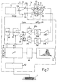
- the device 1a shown in Figure 7 differs from the Figure 1 device by the output of first ultrasonic receiver 22 communicating directly with the input of a signal amplifier 28a, the output of which communicates with the input of a filter 30a (in particular a low-pass filter) having an output connected to the input of a variable-gain amplifier 28b; by the output of second ultrasonic receiver 23 communicating directly with the input of a signal amplifier 29a, the output of which communicates with the input of a filter 31a (in particular a low-pass filter) having an output connected to the input of a variable-gain amplifier 31b; and by the outputs of amplifiers 28b and 31b communicating respectively with a first and a second input 26a, 26b of a multiplexer circuit 26 having a single output connected to the input of multiplexer circuit 34.
- device 1a is identical to, and operates in the same way as, device 1 described with reference to Figure 1, except that the signal generated by each ultrasonic receiver 22, 23 is amplified by a specific variable-gain amplifying chain (comprising amplifiers 28a,28b and 29a,31b respectively) to enable the amplification factor of waveform FO1 to be varied independently from that of waveform FO2; and multiplexer circuit 26 provides for selecting one or other of the signals generated by receivers 22, 23.
- a specific variable-gain amplifying chain comprising amplifiers 28a,28b and 29a,31b respectively
Landscapes
- Health & Medical Sciences (AREA)
- Life Sciences & Earth Sciences (AREA)
- Biomedical Technology (AREA)
- Heart & Thoracic Surgery (AREA)
- Rheumatology (AREA)
- Biophysics (AREA)
- Nuclear Medicine, Radiotherapy & Molecular Imaging (AREA)
- Pathology (AREA)
- Radiology & Medical Imaging (AREA)
- Engineering & Computer Science (AREA)
- Orthopedic Medicine & Surgery (AREA)
- Physics & Mathematics (AREA)
- Medical Informatics (AREA)
- Molecular Biology (AREA)
- Surgery (AREA)
- Animal Behavior & Ethology (AREA)
- General Health & Medical Sciences (AREA)
- Public Health (AREA)
- Veterinary Medicine (AREA)
- Ultra Sonic Daignosis Equipment (AREA)
Applications Claiming Priority (2)
| Application Number | Priority Date | Filing Date | Title |
|---|---|---|---|
| IT97TO000362A IT1292288B1 (it) | 1997-04-24 | 1997-04-24 | Dispositivo di misura ad ultrasuoni per la rilevazione della densita' e struttura ossea. |
| ITTO970362 | 1997-04-24 |
Publications (2)
| Publication Number | Publication Date |
|---|---|
| EP0873717A2 true EP0873717A2 (de) | 1998-10-28 |
| EP0873717A3 EP0873717A3 (de) | 1999-02-10 |
Family
ID=11415677
Family Applications (1)
| Application Number | Title | Priority Date | Filing Date |
|---|---|---|---|
| EP98107423A Withdrawn EP0873717A3 (de) | 1997-04-24 | 1998-04-23 | Ultraschall-Messvorrichtung zur Bestimmung der Dichte und der Beschaffenheit von Knochengewebe |
Country Status (3)
| Country | Link |
|---|---|
| US (1) | US6436042B1 (de) |
| EP (1) | EP0873717A3 (de) |
| IT (1) | IT1292288B1 (de) |
Cited By (1)
| Publication number | Priority date | Publication date | Assignee | Title |
|---|---|---|---|---|
| EP2033579A1 (de) * | 2007-09-06 | 2009-03-11 | Aloka Co., Ltd. | Diagnostisches Ultraschallgerät |
Families Citing this family (14)
| Publication number | Priority date | Publication date | Assignee | Title |
|---|---|---|---|---|
| AU2003301407B2 (en) | 2002-10-15 | 2010-04-22 | Irm Llc | Compositions and methods for inducing osteogenesis |
| US8202219B2 (en) * | 2004-02-23 | 2012-06-19 | Cyberlogic, Inc. | Ultrasonic bone assessment apparatus and method |
| US20070238992A1 (en) * | 2006-02-01 | 2007-10-11 | Sdgi Holdings, Inc. | Implantable sensor |
| US7328131B2 (en) | 2006-02-01 | 2008-02-05 | Medtronic, Inc. | Implantable pedometer |
| US8016859B2 (en) * | 2006-02-17 | 2011-09-13 | Medtronic, Inc. | Dynamic treatment system and method of use |
| US7993269B2 (en) | 2006-02-17 | 2011-08-09 | Medtronic, Inc. | Sensor and method for spinal monitoring |
| US20070197895A1 (en) * | 2006-02-17 | 2007-08-23 | Sdgi Holdings, Inc. | Surgical instrument to assess tissue characteristics |
| US7918796B2 (en) * | 2006-04-11 | 2011-04-05 | Warsaw Orthopedic, Inc. | Volumetric measurement and visual feedback of tissues |
| US7901356B2 (en) * | 2006-12-13 | 2011-03-08 | Cyberlogic, Inc. | Ultrasonic bone assessment apparatus and method |
| US9615814B2 (en) * | 2006-12-13 | 2017-04-11 | Cyberlogic, Inc. | Ultrasonic bone assessment apparatus and method |
| US7862510B2 (en) * | 2007-02-09 | 2011-01-04 | Cyberlogic, Inc. | Ultrasonic bone assessment apparatus and method |
| US20080228072A1 (en) * | 2007-03-16 | 2008-09-18 | Warsaw Orthopedic, Inc. | Foreign Body Identifier |
| US8343923B2 (en) * | 2007-11-09 | 2013-01-01 | Washington University | Use of notch signaling regulators for modulating osteogenesis |
| EP2214013A1 (de) | 2009-01-28 | 2010-08-04 | Universitätsklinikum Freiburg | Verfahren zur Behandlung von Knochenerkrankungen |
Citations (1)
| Publication number | Priority date | Publication date | Assignee | Title |
|---|---|---|---|---|
| US5343863A (en) * | 1988-05-11 | 1994-09-06 | Lunar Corporation | Ultrasonic densitometer device and method |
Family Cites Families (8)
| Publication number | Priority date | Publication date | Assignee | Title |
|---|---|---|---|---|
| EP0299906A3 (de) * | 1987-07-16 | 1990-06-13 | The University Of Melbourne | In vivo Knochenbeschaffenheitsmessung |
| US5054490A (en) * | 1988-05-11 | 1991-10-08 | Lunar Corporation | Ultrasonic densitometer device and method |
| US5197475A (en) * | 1988-08-10 | 1993-03-30 | The Board Of Regents, The University Of Texas System | Method and apparatus for analyzing material properties using ultrasound |
| GB2257253B (en) * | 1991-06-17 | 1995-01-11 | Christian Mcdonald Langton | Ultrasound bone analyser |
| GB9213220D0 (en) * | 1992-06-22 | 1992-08-05 | Langton Christian M | Ultrasound bone analyser |
| US5396891A (en) * | 1993-04-07 | 1995-03-14 | Osteo Sciences Corporation | System and method for external acoustic bone velocity measurement |
| IT1268599B1 (it) * | 1994-01-14 | 1997-03-06 | Igea Srl | Sistema di misura ad ultrasuoni per la rilevazione della densita' e struttura ossea. |
| US5730135A (en) * | 1995-09-12 | 1998-03-24 | Horiba, Ltd. | Ultrasonic bone diagnostic apparatus and method |
-
1997
- 1997-04-24 IT IT97TO000362A patent/IT1292288B1/it active IP Right Grant
-
1998
- 1998-04-23 EP EP98107423A patent/EP0873717A3/de not_active Withdrawn
- 1998-04-24 US US09/066,145 patent/US6436042B1/en not_active Expired - Fee Related
Patent Citations (1)
| Publication number | Priority date | Publication date | Assignee | Title |
|---|---|---|---|---|
| US5343863A (en) * | 1988-05-11 | 1994-09-06 | Lunar Corporation | Ultrasonic densitometer device and method |
Cited By (1)
| Publication number | Priority date | Publication date | Assignee | Title |
|---|---|---|---|---|
| EP2033579A1 (de) * | 2007-09-06 | 2009-03-11 | Aloka Co., Ltd. | Diagnostisches Ultraschallgerät |
Also Published As
| Publication number | Publication date |
|---|---|
| ITTO970362A1 (it) | 1998-10-24 |
| US6436042B1 (en) | 2002-08-20 |
| IT1292288B1 (it) | 1999-01-29 |
| ITTO970362A0 (de) | 1997-04-24 |
| EP0873717A3 (de) | 1999-02-10 |
Similar Documents
| Publication | Publication Date | Title |
|---|---|---|
| US6436042B1 (en) | Ultrasonic measuring device for determining bone density and structure | |
| US5564423A (en) | Ultrasonic measurement system for the determination of bone density and structure | |
| US6364837B1 (en) | Contact digital ultrasonic densitometer | |
| EP0728443B1 (de) | Ultraschall-Dichtemessgerät und Verfahren | |
| EP0480554B1 (de) | Ultraschall-Dichtemessgerät | |
| EP0498281B1 (de) | Messung der Übertragungsgeschwindigkeit der Pulswelle | |
| US6699197B2 (en) | Pulse-wave-propagation-velocity-related-information obtaining apparatus | |
| US5119820A (en) | Ultrasonic densitometer device and method | |
| KR101827522B1 (ko) | 비접촉 심박 측정 장치 및 그 방법 | |
| US7862510B2 (en) | Ultrasonic bone assessment apparatus and method | |
| EP2093588B1 (de) | Ultrabreitband-Impulssensor und Verfahren dafür | |
| US5520183A (en) | Fat depth measuring apparatus | |
| US4601295A (en) | Ear pathology diagnosis apparatus and method | |
| EP0060116A1 (de) | Gerät zur Messung von Kreislauf-Parametern | |
| JPH04501519A (ja) | 超音波骨分析方法及び装置 | |
| EP0299906A3 (de) | In vivo Knochenbeschaffenheitsmessung | |
| EP1344488A3 (de) | Verfahren und Vorrichtung zur Diagnose mit Licht | |
| EP0103640B1 (de) | Vorrichtung und verfahren zur diagnose der ohrpathologie | |
| CA1219330A (en) | Ear pathology diagnosis apparatus and method | |
| US6196971B1 (en) | Chord propagation velocity measurement system and method for an ultrasound imaging system | |
| Yamamura et al. | Characterization of masticatory and swallowing sounds using wavelet analysis | |
| JP2002065620A (ja) | 脈波検出装置 | |
| JPH1078437A (ja) | 血糖計 | |
| AU665978B2 (en) | Fat depth measuring apparatus | |
| JPH0659805A (ja) | 手の仕草に従って制御信号を発生する装置 |
Legal Events
| Date | Code | Title | Description |
|---|---|---|---|
| PUAI | Public reference made under article 153(3) epc to a published international application that has entered the european phase |
Free format text: ORIGINAL CODE: 0009012 |
|
| AK | Designated contracting states |
Kind code of ref document: A2 Designated state(s): DE ES FR GB IT |
|
| AX | Request for extension of the european patent |
Free format text: AL;LT;LV;MK;RO;SI |
|
| PUAL | Search report despatched |
Free format text: ORIGINAL CODE: 0009013 |
|
| AK | Designated contracting states |
Kind code of ref document: A3 Designated state(s): AT BE CH CY DE DK ES FI FR GB GR IE IT LI LU MC NL PT SE |
|
| AX | Request for extension of the european patent |
Free format text: AL;LT;LV;MK;RO;SI |
|
| 17P | Request for examination filed |
Effective date: 19990716 |
|
| AKX | Designation fees paid |
Free format text: DE ES FR GB IT |
|
| 17Q | First examination report despatched |
Effective date: 20030903 |
|
| STAA | Information on the status of an ep patent application or granted ep patent |
Free format text: STATUS: THE APPLICATION IS DEEMED TO BE WITHDRAWN |
|
| 18D | Application deemed to be withdrawn |
Effective date: 20040402 |