EP0873742B1 - Dispositif pour laver le corps humain - Google Patents
Dispositif pour laver le corps humain Download PDFInfo
- Publication number
- EP0873742B1 EP0873742B1 EP97305539A EP97305539A EP0873742B1 EP 0873742 B1 EP0873742 B1 EP 0873742B1 EP 97305539 A EP97305539 A EP 97305539A EP 97305539 A EP97305539 A EP 97305539A EP 0873742 B1 EP0873742 B1 EP 0873742B1
- Authority
- EP
- European Patent Office
- Prior art keywords
- wheelchair
- user
- opening
- warm water
- wall member
- Prior art date
- Legal status (The legal status is an assumption and is not a legal conclusion. Google has not performed a legal analysis and makes no representation as to the accuracy of the status listed.)
- Expired - Lifetime
Links
- 238000005406 washing Methods 0.000 title claims description 40
- XLYOFNOQVPJJNP-UHFFFAOYSA-N water Substances O XLYOFNOQVPJJNP-UHFFFAOYSA-N 0.000 claims description 66
- 238000007599 discharging Methods 0.000 claims description 10
- 230000000994 depressogenic effect Effects 0.000 claims description 4
- 238000003780 insertion Methods 0.000 claims description 2
- 230000037431 insertion Effects 0.000 claims description 2
- 229920002430 Fibre-reinforced plastic Polymers 0.000 description 4
- 239000011151 fibre-reinforced plastic Substances 0.000 description 4
- 238000005452 bending Methods 0.000 description 3
- 239000007788 liquid Substances 0.000 description 3
- 239000000463 material Substances 0.000 description 3
- 239000004033 plastic Substances 0.000 description 3
- 229920003023 plastic Polymers 0.000 description 3
- 230000007547 defect Effects 0.000 description 2
- 239000002453 shampoo Substances 0.000 description 2
- 230000001954 sterilising effect Effects 0.000 description 2
- 238000004891 communication Methods 0.000 description 1
- 238000009833 condensation Methods 0.000 description 1
- 230000005494 condensation Effects 0.000 description 1
- 238000010276 construction Methods 0.000 description 1
- 238000010586 diagram Methods 0.000 description 1
- 239000012530 fluid Substances 0.000 description 1
- 238000012423 maintenance Methods 0.000 description 1
- 239000000203 mixture Substances 0.000 description 1
- 229920000915 polyvinyl chloride Polymers 0.000 description 1
- 239000004800 polyvinyl chloride Substances 0.000 description 1
Images




Classifications
-
- A—HUMAN NECESSITIES
- A61—MEDICAL OR VETERINARY SCIENCE; HYGIENE
- A61H—PHYSICAL THERAPY APPARATUS, e.g. DEVICES FOR LOCATING OR STIMULATING REFLEX POINTS IN THE BODY; ARTIFICIAL RESPIRATION; MASSAGE; BATHING DEVICES FOR SPECIAL THERAPEUTIC OR HYGIENIC PURPOSES OR SPECIFIC PARTS OF THE BODY
- A61H9/00—Pneumatic or hydraulic massage
-
- A—HUMAN NECESSITIES
- A61—MEDICAL OR VETERINARY SCIENCE; HYGIENE
- A61H—PHYSICAL THERAPY APPARATUS, e.g. DEVICES FOR LOCATING OR STIMULATING REFLEX POINTS IN THE BODY; ARTIFICIAL RESPIRATION; MASSAGE; BATHING DEVICES FOR SPECIAL THERAPEUTIC OR HYGIENIC PURPOSES OR SPECIFIC PARTS OF THE BODY
- A61H35/00—Baths for specific parts of the body
- A61H2035/004—Baths for specific parts of the body for the whole body except the head
-
- A—HUMAN NECESSITIES
- A61—MEDICAL OR VETERINARY SCIENCE; HYGIENE
- A61H—PHYSICAL THERAPY APPARATUS, e.g. DEVICES FOR LOCATING OR STIMULATING REFLEX POINTS IN THE BODY; ARTIFICIAL RESPIRATION; MASSAGE; BATHING DEVICES FOR SPECIAL THERAPEUTIC OR HYGIENIC PURPOSES OR SPECIFIC PARTS OF THE BODY
- A61H2203/00—Additional characteristics concerning the patient
- A61H2203/04—Position of the patient
- A61H2203/0425—Sitting on the buttocks
- A61H2203/0431—Sitting on the buttocks in 90°/90°-position, like on a chair
-
- A—HUMAN NECESSITIES
- A61—MEDICAL OR VETERINARY SCIENCE; HYGIENE
- A61H—PHYSICAL THERAPY APPARATUS, e.g. DEVICES FOR LOCATING OR STIMULATING REFLEX POINTS IN THE BODY; ARTIFICIAL RESPIRATION; MASSAGE; BATHING DEVICES FOR SPECIAL THERAPEUTIC OR HYGIENIC PURPOSES OR SPECIFIC PARTS OF THE BODY
- A61H2203/00—Additional characteristics concerning the patient
- A61H2203/04—Position of the patient
- A61H2203/0443—Position of the patient substantially horizontal
- A61H2203/0456—Supine
Definitions
- This invention relates generally to a device for washing a body of a user sitting in or reclining on a wheelchair and, more specifically, to a body washer adapted to be set on a floor having a water discharging port, such as on a bath room floor, and to inject droplets of warm water through a plurality of shower nozzles for washing the body of the user.
- JP-A-7-308355 discloses a body washer as shown in Figs. 9-11.
- Figs. 9-11 designated generally as 1 is a housing made of a hard plastic material and adapted to accommodate a user (A), such as a patient, sitting in a wheelchair 11.
- the housing 1 is in the form of a box and has an entrance at a rear side (left side in Figs. 9 and 10) thereof through which the user sitting in the wheelchair 11 can enter the housing 1.
- a door 10 is provided for opening and closing the entrance.
- the housing 1 has a top wall provided with a recess 3 at its rear end so that the head of the user protrudes from the housing 1 through the recess 3.
- the housing 1 has a bottom plate 4 reinforced by a bottom frame 5 made from grid-like rectangular pipes.
- the bottom plate 4 is provided with a pair of longitudinally extending, depressed portions 4a for guiding the left and right wheels 12 of the wheelchair 11, respectively, so that the user is positioned in the center in the lateral direction of the housing 1.
- the housing 1 has left and right side walls 6 each having a double-walled structure.
- each of the side walls 6 is composed of an inner wall 6a and an outer wall 6b defining therebetween a space 6c in which an inverted U-shaped pipe 7 is secured.
- a plurality of branched pipes 8 extend from each of the U-shaped pipes 7 and are oriented toward the user positioned in the housing 1.
- Each branched pipe 8 is equipped with a nozzle 9 at its tip end.
- Each of the U-shaped pipe 7 is connected to an output pipe of a boiler (not shown) through a pump.
- Designated as 13 is a head rest attached to the door 10 for supporting the head of the user (A) thereon.
- a pipe 14 laterally extends within the housing 1 for being gripped by the user (A).
- Designated as 15 is a shower nozzle used for washing the hair of the user (A).
- the shower nozzle 15 is connected to a flexible tube extending out of the housing 1.
- the above washer has been found to have the following defects. Since the bottom of the housing 1 is closed with the bottom plate 4, the weight and height of the washer are increased. Further, the structure is complicated so that the costs are increased. Since the bottom plate 4 is located at a level higher than the floor, it is necessary to use gang boards in order to displace the wheelchair 11 from the floor to the bottom plate 4. Such gang boards hinder the movement of an assistant for the user. Since the U-shaped pipes 7 are supported on the bottom plate 4 and rigid branched pipes 8 are located within the side walls 6, it is necessary to disassemble the side walls 6 and the bottom plate 4 in order to connect the pipes or to perform piping maintenance works. Further, since the U-shaped pipes 7 are connected through a pump to the output pipe from the boiler, the temperature and the flow rate of the warm water discharged from the nozzles 9 are apt to change when the water pressure of the city water is varied.
- an object of the present invention to provide a washing device which is devoid of the above-described defects of the conventional washer.
- a device for washing a user sitting in a wheelchair comprising:
- the present invention also provides a device for washing a user reclining on a wheelchair, comprising:
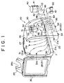
- the reference numeral 20 designates an open-bottomed housing member placed on a floor F.
- the housing member 20 is made of a fiber-reinforced plastic and defines therewithin a washing chamber for washing a user (A), such as a patient, sitting in a wheelchair 65.
- the housing member 20 has a top wall member 26 opposite the open bottom, opposing side wall members 28, a front wall member 28a and a rear opening 25 opposite the front wall member 28a.
- the rear opening 25 serves as an entrance for the user (A) sitting on the wheelchair 65.
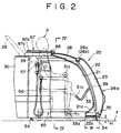
- the top wall member has a U-shaped opening 27 formed in a rear end thereof such that, as shown in Fig. 2, the neck of the user (A) sitting in the wheelchair 65 can be located therein with a gap being defined between the neck and the U-shaped opening 27 when the wheelchair 65 is positioned in the washing chamber.
- a door 30 made of a fiber-reinforced plastic is provided for opening and closing the rear opening 25.
- a back cover 29 having a U-shaped recess 29a is hinged on a top of the door 30 and is rotatable between an open position as shown in Fig. 1 or as shown by the two-dotted line in Fig. 2 and a closed position as shown in Fig. 3 or by the solid line in Fig. 2. In the closed position, the back cover 29 partly closes the gap between the neck of the user (A) and the U-shaped opening 27.
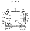
- each of the top wall member 26, side wall members 28 and front wall member 28a is double-walled and includes an inner wall 21 and an outer wall 22 defining a piping space 23 therebetween.
- the piping space is open at its lower end 23a.
- the inner wall of each of the side wall members 28 and the front wall member 28a is inwardly bent or curved at a portion 21a adjacent lower end thereof and then directed vertically downward, so that the housing member 20 has an improved bending and torsional rigidity. Additionally, the falling washing water is directed inward upon impingement against the curved portion 21a so that splash of the falling water on the floor F is minimized.
- each of the side wall members 28 and front wall member 28a has a lower end inwardly bent to form a shelf board 22a, so that the housing member 20 has an improved bending and torsional rigidity.
- the shelf board 22a terminates at a position spaced apart from the inner wall 21 to form the opening 23a therebetween.
- a main tube 35 having an inside diameter of, for example, about 30 mm, made of, for example, a hard plastic such as polyvinyl chloride, and bent into a U-shape is disposed and supported on the shelf board 22a as best seen in Fig. 1. In assembling, the tube 35 is inserted through the opening 23a into the space 23 and placed on the shelf board 22a and is then secured thereon with suitable fixing means.
- a plurality of side nozzles 31a are secured to the inner wall 21 of each of the left and right side-wall members 28.
- Each of the nozzles 31a is connected to a flexible pipe 36 having an inside diameter of, for example, about 9 mm.
- Each of the flexible pipe 36 is disposed in the piping space 23 and branched from the main tube 35 as shown in Fig. 5. More particularly, as shown in Fig. 6, each of the side nozzles 31a is connected to a movable portion of a nozzle holder 32 having a base portion secured to the inner wall 21 of the side wall member 28. The moveable portion is secured to the base portion and rotatable about an axis L thereof.
- Each side nozzle 31a is oriented at an angle of about 30 degrees relative to the axis L of the corresponding nozzle holder 32.
- the orientation of the side nozzle 31a relative to the user may be properly adjusted.
- Each of the rotatable portion of the nozzle holders 32 is shaped into a smooth hemispherical shape so as not to injure the body of the user.
- the base portion of each of the nozzle holders 32 is connected to an elbow 37 which in turn is connected to the flexible pipe 36.
- the inner wall 21 of the front wall member 28a is provided with a front nozzle 31b.
- the front nozzle 31b is connected at a tip end of a position-adjustable hose 33 extending from the inner wall 21.
- a flexible tube 36 extends between the hose 33 and the main tube 35.
- warm water supplied to the main tube 35 is injected as fine droplets from the side nozzles 31a and front nozzle 31b toward the user sitting in the wheelchair 65 accommodated in the housing member 20.
- the direction of the warm water injected from the side nozzles 31a can be adjusted by rotating the moveable portion of the corresponding nozzle holder 32 so that warm water can impinge upon desired portions of the body of the user (A).
- the direction of the warm water injected from the front nozzle 31b can be adjusted by positioning the hose 33 in any desired orientation.
- the front nozzle 31b is used for washing the pubic and anal regions of the user (A).
- the main tube 35 is connected to a warm water-supplying device 40.
- a first pump 43 is connected to a water source for increasing the pressure of water supplied thereto to, for example, 17,65-29,41 N / cm 2 (1.8-3.0 kg/cm 2 ), while a second pump 42 is connected to a hot water source (boiler) 41 for increasing the pressure of hot water supplied thereto to a predetermined pressure of, for example, in the range of 17,65-29,41 N -8 / cm 2 (1.8-3.0 kg/cm 2 ).
- the pumps 42 and 43 are connected to pressure controlling valves 44 and 45, respectively, for controlling the pressure of the hot water fed from the second pump 42 and the pressure of the water fed from the first pump 43, respectively, to a predetermined pressure of, for example, in the range of 14,70-24,51 N / cm 2 (1.5-2.5 kg/cm 2 ).
- First and second flow switches 43a and 42a are interposed between the first pump 43 and the pressure controlling valve 45 and between the second pump 42 and the pressure controlling valve 44, respectively, and are operable to stop respective pumps 43 and 42 when the flow rate of the water and hot water passing therethrough exceeds a predetermined value.
- Designated as 46 is a mixer connected to the pressure controlling valves 44 and 45 for mixing the water having a controlled pressure with the hot water having a controlled pressure in a suitable mixing ratio to obtain warm water having a predetermined temperature of, for example, about 43°C.
- the mixing ratio can be manually set as desired.
- the mixer 46 is connected to the main tube 35 through a feed pipe 50.
- a high temperature sensor 47 and a shut off valve (solenoid valve) 48 are disposed in the feed pipe 50.
- the sensor 47 is adapted for detecting the temperature of the warm water discharged from the mixer 46.
- the shut off valve 48 electrically coupled to the sensor 47 is operated for stopping the passage of the warm water therethrough.
- a manual switching valve 51, 52 and 53 which are connected in parallel to the feed pipe 50.
- the valve 51 is connected to the main tube 35 through a flexible pipe 54.
- the valves 52 have outlet sides connected through mixers 55 of an ejector type to the flexible pipe 54.
- the mixers 55 have respective suction ports 55a and 55b connected to a sterilizing liquid tank 60 and a body shampoo tank 61 through suction hoses 58 and 59, respectively.
- the valve 53 is connected to a hand shower 57 through a flexible hose 56 extending out of the housing member 20 (see Fig. 1).
- the hand shower is suitably used for washing the hair of the user (A).
- a low temperature sensor 62 and a switching valve 63 are disposed in the pipe 54.
- the sensor 62 is adapted for detecting the temperature of the warm water passing therethrough.
- the valve 63 electrically coupled to the sensor 62 is operated for switching the passage of the warm water from the main tube 35 to a discharge side.
- the switching valve 63 directs the warm water toward the main tube 35.
- An automatic discharging valve 64 of a spring-biased type is connected to the main tube 35 to release the warm water therefrom when the pressure therewithin is below a predetermined pressure.
- the automatic discharging valve 64 is closed by the pressure generated in the main tube 35 when the switching valve 63 is so shifted as to feed the warm water from the flexible pipe 54 to the main tube 35, thereby permit the warm water to be injected through the nozzles 31a and 31b.
- the automatic discharging valve 64 opens so that the warm water within the main tube 35 and the flexible pipes 36 is discharged therefrom through a drain pipe connected to a lower side of the main tube 35, since the nozzles 31a and 31b are in fluid communication with the atmosphere.
- the liquid initially injected from the nozzles 31a and 31b is not the water cooled during the retaining in the main tube 35 but is warm water freshly supplied through the feed pipes 50 and 54.
- height-adjustable legs 34 are attached to the underside of the shelf board 22a for adjusting the gap H between the bottom of the housing member 20 and the floor F to a desired distance.
- the gap H is so adjusted as to minimize the escape of water vapor from the housing member 20 but to maximize the condensation of water vapor during the passage through the gap H.
- the optimum gap H depends upon the distance W between the outer and inner walls 21 and 22. Generally, the gap H is in the range of 3-5 cm and the distance W is in the range of 15-20 cm.
- the height-adjustable legs 34 also serve to support the housing member 20 on the floor F in a stable position.
- the outer wall 22 of the top wall member 26 is provided with a groove 26a extending along an outer periphery of the outer wall 22 such that the U-shaped opening 27 is surrounded by the groove 26a.
- the groove 26a is sloped down in the direction from the rear side to the front side and is provided with an opening 26b in the middle portion of the front side.
- the opening is connected to an upper end of a discharging hose 39.
- the discharging hose 39 extends through the piping space 23 and terminates at the lower end thereof at a position adjacent a lower end of the piping space 23.
- a pair of semicircular plate members 67a and 67a are pivotally supported by a pin 68 on the top wall member 26 such that rotation of the plate members can open and close the U-shaped opening 27.
- the plate members 67a and 67a are made of a soft plastic material and constitute a neck cover 67.
- Each of the plate members 67a and 67a has a depressed portion 67b so that the gap between the neck of the user (A) and the U-shaped opening 27 is closed with the plate members 67a and 67a with the neck of the user (A) being fitted into an opening defined by the depressed portions 67b and 67b when the plate members 67a and 67a are in the closed position.
- the water vapor within the housing member 20 is prevented from escaping therefrom through the gap between the neck of the user (A) and the U-shaped opening 27.
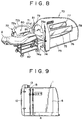
- Fig. 8 depicts a second embodiment of the present invention. Since the construction of the housing member and the warm water supplying system of the second embodiment are substantially the same as those in the first embodiment, the detailed description thereof will be omitted here. Thus, the following description will be made mainly on features of the second embodiment different from those of the first embodiment.
- the reference numeral 70 designates an open-bottomed housing member placed on a floor.
- the housing member 20 is made of a fiber-reinforced plastic and defines therewithin a washing chamber for washing a user (A), such as a patient, reclining on a wheelchair 82.
- the housing member 70 has an elongated box-like form which is open at the bottom and a rear end.
- the rear opening 71 serves as an entrance for the user (A) reclining on the wheelchair 82.
- each of side wall members 73 and front wall member is double-walled to define a piping space therebetween.
- the piping space is open at its lower end 23a.
- the inner wall 74 of each of the side wall members 73 and the front wall member is inwardly bent or curved at a portion 74a adjacent lower end thereof and then directed vertically downward, so that the housing member 70 has an improved bending and torsional rigidity. Additionally, the falling washing water is directed inward upon impingement against the curved portion 74a so that splash of the falling water on the floor is minimized.
- a plurality of side nozzles (for example, five nozzles) are secured to the inner wall 74 of each of the left and right side-wall members 73 similar to the first embodiment.
- a door 72 made of a fiber-reinforced plastic is provided for opening and closing the rear opening 71.
- the door 72 has an upper end 72b at a level lower than the upper end of the rear opening 71 so that, when the door 71 is closed, there is formed a space 71a between the door 71 and the rear end of the housing member 70.
- the door has a rearwardly inflated portion to form a basin 72a in an upper part of the door 72 such that the head of the user (A) reclining on the wheelchair 82 can be disposed in the basin 72a with a gap being defined therebetween, when the wheelchair 82 is positioned in the washing chamber of the housing member 70 and when the door 72 is closed.
- a closure member such as a neck curtain 79 of a soft sheet material is provided for closing the space 71a of the opening 71 defined above the basin 72a when the door is closed.
- the neck curtain has a U-shaped opening 79a into which the neck of the user (A) reclining on the wheelchair 82 can be fitted when the wheelchair 82 is positioned in the washing chamber of the housing member 70, so that water vapor in the washing chamber is prevented from escaping therefrom through the space 71a.
- One or more (two in the illustrated case) nozzles 80 are provided on the interior wall of the basin 72a for washing the neck and back of the user (A).
- each of the left and right side wall members 73 is provided with a stepped portion 75 for receiving the corresponding elbow of the user (A).
- At least one of the side wall members 73 is provided with a longitudinally extending opening 76 for insertion of a hand of an assisting person and a window 77 above the opening 76 to permit the assisting person to see the user (A) therethrough.
- the opening 76 may be closed by a closure means such as a curtain 78.
- the assisting person can wash, with a hand inserted through the opening 76, desired portions of the user (A).
- Designated as 81 is a hand a shower nozzle connected to a tip end of a flexible hose extending out of the housing member 70 for washing the head of the user (A).
Landscapes
- Health & Medical Sciences (AREA)
- Epidemiology (AREA)
- Pain & Pain Management (AREA)
- Physical Education & Sports Medicine (AREA)
- Rehabilitation Therapy (AREA)
- Life Sciences & Earth Sciences (AREA)
- Animal Behavior & Ethology (AREA)
- General Health & Medical Sciences (AREA)
- Public Health (AREA)
- Veterinary Medicine (AREA)
- Devices For Medical Bathing And Washing (AREA)
Claims (19)
- Dispositif pour le lavage d'un utilisateur assis dans une chaise roulante comprenant :un élément d'habitacle (20) à fond ouvert définissant une chambre de lavage enclose dans cet élément et muni d'un élément de paroi supérieur (26) du côté opposé au dit fond ouvert, d'éléments de paroi latéraux se faisant face (28), d'un élément de paroi antérieur (28a) et d'une ouverture à l'arrière (35) faisant face au dit élément de paroi antérieur, chacun des dits éléments de paroi latéraux et élément de paroi antérieure étant à double épaisseur et comprenant une paroi interne et une paroi externe (21, 22) entre lesquelles est compris un espace (23) destiné aux tuyauteries ;une ouverture en forme de U (27) à l'arrière dudit élément de paroi supérieur de façon à ce que le cou dudit utilisateur assis dans ladite chaise roulante puisse y être positionné en autorisant un espace entre le cou et ladite ouverture en forme de U lorsque ladite chaise roulante est placée dans ladite chambre de lavage ;une porte (30) permettant d'ouvrir et de fermer ladite ouverture à l'arrière; etplusieurs buses (31a) fixées à une paroi interne dudit élément d'habitacle pour l'injection d'eau chaude vers ledit utilisateur assis dans ladite chaise roulante placée dans ladite chambre de lavage.
- Dispositif selon la revendication 1, dans lequel lesdites buses comprennent une buse antérieure (31b) présente à une extrémité d'un tuyau à position réglable (33) sortant de la paroi interne dudit élément de paroi antérieur.
- Dispositif selon la revendication 1 ou 2, dans lequel ledit élément de paroi supérieur est aussi à double épaisseur et comprend une paroi interne et une paroi externe entre lesquelles est compris un espace.
- Dispositif selon la revendication 3, dans lequel ladite paroi externe dudit élément de paroi supérieur est munie d'une rainure (26a) s'étendant le long d'une périphérie externe de ladite paroi externe de façon à ce que ladite ouverture en forme de U soit encerclée par ladite rainure, dans lequel ladite rainure est munie d'une ouverture à laquelle l'une des extrémités d'un tuyau de décharge (79) est connectée et dans lequel ledit tuyau de décharge s'étend dans ledit espace et ledit espace destiné aux tuyauteries pour aboutir à l'autre extrémité de ce dernier en une position adjacente à une extrémité inférieure dudit espace destiné aux tuyauteries qui est ouvert à une extrémité inférieure de ce dernier.
- Dispositif selon l'une quelconque des revendications précédentes, comprenant en outre deux éléments de plaque (67a), chacun d'entre eux appuyé de façon à pivoter sur ledit élément de paroi supérieur de façon à ce que la rotation desdits éléments de plaque permette d'ouvrir et de fermer ladite ouverture en forme de U, chacun des éléments de plaque disposant d'une position abaissée (67b), de façon à ce que ledit espace entre le cou dudit utilisateur et ladite ouverture en forme de U soit fermé par lesdits éléments de plaque.
- Dispositif selon l'une quelconque des revendications précédentes comprenant en outre des dispositifs servant de pieds à hauteur réglable (34) pour le support dudit élément d'habitacle, permettant d'établir un espace (H) entre ledit élément d'habitacle et le sol sur lequel ledit élément d'habitacle est posé.
- Dispositif pour le lavage d'un utilisateur allongé dans une chaise roulante comprenant :un élément d'habitacle (70) à fond ouvert définissant une chambre de lavage enclose dans cet élément et munie d'un élément de paroi supérieur (26) du côté opposé au dit fond ouvert, d'éléments de paroi latéraux se faisant face (73), d'un élément de paroi antérieur (28a) et d'une ouverture à l'arrière (71) faisant face au dit élément de paroi antérieur, chacun des dits éléments de paroi latéraux et élément de paroi antérieure étant à double épaisseur et comprenant une paroi interne et une paroi externe entre lesquelles est compris un espace (23) destiné aux tuyauteries;plusieurs buses (71a) fixées à une paroi interne (74) dudit élément d'habitacle pour l'injection d'eau chaude vers ledit utilisateur allongé dans ladite chaise roulante placée dans ladite chambre de lavage ;une porte (72) permettant d'ouvrir et de fermer ladite ouverture à l'arrière, ladite porte disposant d'une portion bombée à l'arrière (72a) de façon à ce que la tête dudit utilisateur allongé sur ladite chaise roulante puisse y être posée en autorisant un espace entre la tête et ladite portion bombée lorsque ladite chaise roulante est placée dans ladite chambre de lavage et ladite porte est fermée, etdes dispositifs de fermeture (79) pour la fermeture de l'espace supérieur (71a) de ladite ouverture définie au-dessus de ladite portion bombée lorsque ladite porte est fermée; lesdits dispositifs de fermeture étant munis d'une ouverture en forme de U (79a) dans laquelle le cou de l'utilisateur allongé dans ladite chaise roulante peut être positionné lorsque ladite chaise roulante est placée dans ladite chambre de lavage.
- Dispositif selon la revendication 7, dans lequel la paroi interne de chacun desdits éléments de parois latéraux est munie d'une portion en forme de gradin (75) destinée à accueillir le coude correspondant de l'usager.
- Dispositif selon la revendication 7 ou 8, dans lequel chacun desdits éléments de paroi latérale est muni d'une ouverture (76) pour l'insertion de la main d'une personne prêtant assistance et d'une fenêtre (77) permettant à ladite personne prêtant assistance de voir ledit utilisateur.
- Dispositif selon la revendication 7, 8 ou 9, comprenant en outre une ou plusieurs buses (80) présentes dans la paroi interne de ladite portion bombée pour l'injection d'eau chaude vers le dos de l'utilisateur allongé sur ladite chaise roulante placée dans ledit élément d'habitacle.
- Dispositif selon la revendication 7, 8, 9 ou 10, comprenant en outre des dispositifs servant de pieds à hauteur réglable (34) pour le maintien dudit élément d'habitacle dans une position stable.
- Dispositif selon l'une quelconque des revendications précédentes, dans lequel ledit espace destiné aux tuyauteries est ouvert au niveau de sa partie inférieure (23a).
- Dispositif selon l'une quelconque des revendications précédentes, dans lequel ladite paroi interne de chacun desdits éléments de parois latéraux et dudit élément de paroi antérieur est courbée vers l'intérieur au niveau sa partie inférieure (21a, 74a).
- Dispositif selon l'une quelconque des revendications précédentes, dans lequel la partie inférieure de ladite paroi externe de chacun desdits éléments de parois latéraux et élément de paroi antérieur est courbée vers l'intérieur de façon à constituer un rayon d'étagère (22a) et dans lequel chacune desdites buses est connectée à un tuyau flexible (26) placé dans ledit espace destiné aux tuyauteries et sortant d'un tube principal (35) posé sur et soutenu par ledit rayon d'étagère.
- Dispositif selon la revendication 14, comprenant en outre une soupape de décharge automatique (64) connectée au dit tube principal et adaptée de façon à fonctionner automatiquement pour libérer l'eau chaude dudit tube principal lorsque la pression à l'intérieur dudit tube principal est inférieure à une pression prédéterminée.
- Dispositif selon l'une quelconque des revendications précédentes, comprenant en outre des premiers dispositifs de pompage (43) à connecter à une source d'alimentation en eau pour augmenter la pression de l'eau approvisionnée à ces derniers, des premiers dispositifs de contrôle (44) connectés aux dits premiers dispositifs de pompage pour effectuer le contrôle de la pression de l'eau approvisionnée par lesdits premiers dispositifs de pompage, des seconds dispositifs de pompage (42) à connectés à une source d'alimentation en eau chaude (41) pour augmenter la pression de l'eau chaude approvisionnée à ces derniers, des seconds dispositifs de contrôle (45) connectés aux dits seconds dispositifs de pompage pour effectuer le contrôle de la pression de l'eau chaude approvisionnée par lesdits seconds dispositifs de pompage, un mélangeur (46) connecté aux dits premiers et seconds dispositifs de contrôle pour effectuer le mélange de l'eau sous pression contrôlée à l'eau chaude sous pression contrôlée de façon à obtenir une eau chaude à température prédéterminée, et des tuyauteries (50) assurant l'alimentation de l'eau chaude à température prédéterminée aux dites buses.
- Dispositif selon la revendication 16, comprenant en outre une sonde de haute température (47) connectée aux dites tuyauteries et permettant de détecter la température de l'eau chaude à température prédéterminée, et un clapet d'arrêt (48) placé dans lesdites tuyauteries et couplé à ladite sonde de haute température de façon à arrêter le flux d'eau chaude à température prédéterminée dans ces dernières lorsque la température détectée par ladite sonde de haute température dépasse une température prédéterminée.
- Dispositif selon la revendication 17, comprenant en outre une sonde de basse température (62) connectée aux dites tuyauteries en aval de ladite sonde de haute température et permettant de détecter la température de l'eau chaude à température prédéterminée, et une vanne de commutation (51, 52, 53) placé dans lesdites tuyauteries et couplée à ladite sonde de basse température de façon à orienter le flux d'eau chaude à température prédéterminée vers lesdites buses lorsque la température détectée par ladite sonde de basse température n'est pas inférieure à une température prédéterminée et vers un côté de décharge lorsque la température détectée par ladite sonde de basse température est inférieure à ladite température prédéterminée
- Dispositif selon l'une quelconque des revendications précédentes, comprenant en outre une pomme de douche (81) à une extrémité d'un tuyau flexible sortant dudit élément d'habitacle pour le lavage de la tête dudit utilisateur.
Applications Claiming Priority (6)
| Application Number | Priority Date | Filing Date | Title |
|---|---|---|---|
| JP113377/97 | 1997-04-14 | ||
| JP09113377A JP3094123B2 (ja) | 1997-04-14 | 1997-04-14 | 身体洗浄用給湯装置及び身体洗浄装置 |
| JP11337797 | 1997-04-14 | ||
| JP17646197 | 1997-06-16 | ||
| JP17646197A JP3223316B2 (ja) | 1997-06-16 | 1997-06-16 | 身体洗浄装置 |
| JP176461/97 | 1997-06-16 |
Publications (3)
| Publication Number | Publication Date |
|---|---|
| EP0873742A2 EP0873742A2 (fr) | 1998-10-28 |
| EP0873742A3 EP0873742A3 (fr) | 2000-01-19 |
| EP0873742B1 true EP0873742B1 (fr) | 2004-03-03 |
Family
ID=26452367
Family Applications (1)
| Application Number | Title | Priority Date | Filing Date |
|---|---|---|---|
| EP97305539A Expired - Lifetime EP0873742B1 (fr) | 1997-04-14 | 1997-07-22 | Dispositif pour laver le corps humain |
Country Status (4)
| Country | Link |
|---|---|
| US (2) | US5953770A (fr) |
| EP (1) | EP0873742B1 (fr) |
| CN (2) | CN1112893C (fr) |
| DE (1) | DE69727910T2 (fr) |
Families Citing this family (16)
| Publication number | Priority date | Publication date | Assignee | Title |
|---|---|---|---|---|
| CH693055A5 (de) * | 1998-08-13 | 2003-02-14 | Martin Wyss | Vorrichtung aus einer Kombination einer Badewanne mit einer Duschwanne. |
| EP1276860B1 (fr) * | 2000-04-28 | 2007-09-26 | Sangamo Biosciences Inc. | Base de donnees de sequences regulatrices, leurs procedes d'elaboration et d'utilisation |
| US7841027B2 (en) * | 2003-07-17 | 2010-11-30 | Immediate Response Technologies | Partition system |
| GB2466507B (en) * | 2008-12-24 | 2012-03-28 | Dlp Ltd | Pumped shower draining device |
| US8539619B2 (en) * | 2009-09-14 | 2013-09-24 | Technology Patents, Llc | Cleaning systems and/or methods |
| US9173528B1 (en) * | 2009-10-30 | 2015-11-03 | William R. Shrewsbury | Disability shower with air purge system |
| US9581255B2 (en) | 2012-07-23 | 2017-02-28 | Henning, Inc. | Multiple proportion delivery systems and methods |
| WO2015038821A1 (fr) * | 2013-09-12 | 2015-03-19 | Jaguan Mauro | Dispositif portatif amélioré de massage pour thérapie de relaxation de la tête |
| US20150189966A1 (en) * | 2014-01-09 | 2015-07-09 | Nancy Y. KIM | Automatic hair and body cleaning apparatus |
| CN105266689B (zh) * | 2014-05-29 | 2020-01-10 | 酒井医疗株式会社 | 沐浴装置 |
| ES2590337B1 (es) * | 2016-05-27 | 2017-09-06 | Antonio Luis ALONSO HOLGADO | Cabina de desinfección de virus y gérmenes patógenos e higiene personal |
| WO2019033195A1 (fr) * | 2017-08-16 | 2019-02-21 | Sikora York | Procédés et systèmes de secours pour gestion thermique du système de spa |
| CN109620692B (zh) * | 2019-01-23 | 2021-04-23 | 广东工业大学 | 一种智能洗吹发按摩器 |
| CN110056062A (zh) * | 2019-05-31 | 2019-07-26 | 台州市雅妮莎洁具股份有限公司 | 一种马桶的清洗器结构 |
| US11330909B1 (en) | 2021-09-07 | 2022-05-17 | Giftedness And Creativity Company | Lovemaking apparatus for the disabled with pivoting tabletop platform and pivoting wheelchair seat |
| IT202100028406A1 (it) | 2021-11-09 | 2023-05-09 | Francesco Benedetto Tocci | Dispositivo e sistema semiautomatico per l’igiene e la cura della persona |
Family Cites Families (6)
| Publication number | Priority date | Publication date | Assignee | Title |
|---|---|---|---|---|
| US3613127A (en) * | 1969-11-05 | 1971-10-19 | James M Bond | Apparatus facilitating care of a bedfast patient |
| US5136735A (en) * | 1991-03-07 | 1992-08-11 | Zimmerman Phyllis E | Immobile patient shower and skin care unit |
| US5233706A (en) * | 1992-01-08 | 1993-08-10 | Maehr Jeffrey T | Water conserving shower apparatus |
| JP3056886B2 (ja) * | 1992-07-08 | 2000-06-26 | 酒井医療株式会社 | シャワーバス装置 |
| JP3314166B2 (ja) * | 1994-03-22 | 2002-08-12 | キヤノン・エヌ・ティー・シー株式会社 | 身体洗浄装置 |
| JPH09122035A (ja) * | 1995-11-02 | 1997-05-13 | Matsushita Electric Ind Co Ltd | 浴室用椅子 |
-
1997
- 1997-07-09 CN CN97114533A patent/CN1112893C/zh not_active Expired - Fee Related
- 1997-07-22 EP EP97305539A patent/EP0873742B1/fr not_active Expired - Lifetime
- 1997-07-22 DE DE69727910T patent/DE69727910T2/de not_active Expired - Fee Related
- 1997-07-22 US US08/898,495 patent/US5953770A/en not_active Expired - Fee Related
-
1999
- 1999-05-17 US US09/312,487 patent/US5996140A/en not_active Expired - Fee Related
-
2002
- 2002-08-07 CN CNB02129710XA patent/CN1212489C/zh not_active Expired - Fee Related
Also Published As
| Publication number | Publication date |
|---|---|
| US5953770A (en) | 1999-09-21 |
| CN1447072A (zh) | 2003-10-08 |
| EP0873742A3 (fr) | 2000-01-19 |
| CN1196218A (zh) | 1998-10-21 |
| CN1112893C (zh) | 2003-07-02 |
| US5996140A (en) | 1999-12-07 |
| CN1212489C (zh) | 2005-07-27 |
| DE69727910D1 (de) | 2004-04-08 |
| EP0873742A2 (fr) | 1998-10-28 |
| DE69727910T2 (de) | 2004-12-23 |
Similar Documents
| Publication | Publication Date | Title |
|---|---|---|
| US5953770A (en) | Device for washing human body | |
| US9032563B2 (en) | Apparatus and method for treating excreta | |
| US5906012A (en) | Automatic shampoo machine | |
| US12365016B2 (en) | Automatic washer for continuous positive airway pressure equipment | |
| US12286781B2 (en) | Toilet bowl bidet capable of preventing droplets from splashing when toilet is flushed | |
| KR100797578B1 (ko) | 자동 배변 처리장치 | |
| US5839135A (en) | Device for washing human body lying on stretcher | |
| US3447166A (en) | Combined bathing apparatus,commode,etc.,for convalescent patients and the like | |
| JP3118539B2 (ja) | 身体洗浄装置 | |
| US20010025389A1 (en) | Human body washing device | |
| JP3125139B2 (ja) | 患者の洗浄装置 | |
| KR101782140B1 (ko) | 수통 세척기 | |
| JP3314166B2 (ja) | 身体洗浄装置 | |
| KR20010082952A (ko) | 자동 목욕기 | |
| JP3223316B2 (ja) | 身体洗浄装置 | |
| JP3590312B2 (ja) | シャワー入浴洗浄装置 | |
| KR20150019824A (ko) | 간병용 침대 | |
| JP2569956Y2 (ja) | 入退容易なシャワーバス | |
| KR200358759Y1 (ko) | 좌훈욕 및 얼굴스팀기 | |
| JP7672829B2 (ja) | 入浴装置 | |
| JP3094123B2 (ja) | 身体洗浄用給湯装置及び身体洗浄装置 | |
| JP3936301B2 (ja) | 上肢用部分浴槽 | |
| JPH1156953A (ja) | シャワー風呂 | |
| JP2001269365A (ja) | 排泄物処理装置 | |
| KR930005258Y1 (ko) | 좌변기용 국부세척기의 부설 및 세제공급장치 |
Legal Events
| Date | Code | Title | Description |
|---|---|---|---|
| PUAI | Public reference made under article 153(3) epc to a published international application that has entered the european phase |
Free format text: ORIGINAL CODE: 0009012 |
|
| AK | Designated contracting states |
Kind code of ref document: A2 Designated state(s): AT BE CH DE DK ES FI FR GB GR IE IT LI LU MC NL PT SE |
|
| PUAL | Search report despatched |
Free format text: ORIGINAL CODE: 0009013 |
|
| AK | Designated contracting states |
Kind code of ref document: A3 Designated state(s): AT BE CH DE DK ES FI FR GB GR IE IT LI LU MC NL PT SE |
|
| 17P | Request for examination filed |
Effective date: 20000718 |
|
| AKX | Designation fees paid |
Free format text: AT BE CH DE DK ES FI FR GB GR IE IT LI LU MC NL PT SE |
|
| GRAH | Despatch of communication of intention to grant a patent |
Free format text: ORIGINAL CODE: EPIDOS IGRA |
|
| GRAS | Grant fee paid |
Free format text: ORIGINAL CODE: EPIDOSNIGR3 |
|
| GRAA | (expected) grant |
Free format text: ORIGINAL CODE: 0009210 |
|
| AK | Designated contracting states |
Kind code of ref document: B1 Designated state(s): DE FR GB IT |
|
| REG | Reference to a national code |
Ref country code: GB Ref legal event code: FG4D |
|
| REG | Reference to a national code |
Ref country code: IE Ref legal event code: FG4D |
|
| REF | Corresponds to: |
Ref document number: 69727910 Country of ref document: DE Date of ref document: 20040408 Kind code of ref document: P |
|
| ET | Fr: translation filed | ||
| PLBE | No opposition filed within time limit |
Free format text: ORIGINAL CODE: 0009261 |
|
| STAA | Information on the status of an ep patent application or granted ep patent |
Free format text: STATUS: NO OPPOSITION FILED WITHIN TIME LIMIT |
|
| 26N | No opposition filed |
Effective date: 20041206 |
|
| REG | Reference to a national code |
Ref country code: IE Ref legal event code: MM4A |
|
| PGFP | Annual fee paid to national office [announced via postgrant information from national office to epo] |
Ref country code: DE Payment date: 20090129 Year of fee payment: 12 |
|
| PGFP | Annual fee paid to national office [announced via postgrant information from national office to epo] |
Ref country code: GB Payment date: 20090107 Year of fee payment: 12 |
|
| PGFP | Annual fee paid to national office [announced via postgrant information from national office to epo] |
Ref country code: IT Payment date: 20090131 Year of fee payment: 12 |
|
| PGFP | Annual fee paid to national office [announced via postgrant information from national office to epo] |
Ref country code: FR Payment date: 20090128 Year of fee payment: 12 |
|
| GBPC | Gb: european patent ceased through non-payment of renewal fee |
Effective date: 20090722 |
|
| REG | Reference to a national code |
Ref country code: FR Ref legal event code: ST Effective date: 20100331 |
|
| PG25 | Lapsed in a contracting state [announced via postgrant information from national office to epo] |
Ref country code: FR Free format text: LAPSE BECAUSE OF NON-PAYMENT OF DUE FEES Effective date: 20090731 |
|
| PG25 | Lapsed in a contracting state [announced via postgrant information from national office to epo] |
Ref country code: GB Free format text: LAPSE BECAUSE OF NON-PAYMENT OF DUE FEES Effective date: 20090722 |
|
| PG25 | Lapsed in a contracting state [announced via postgrant information from national office to epo] |
Ref country code: DE Free format text: LAPSE BECAUSE OF NON-PAYMENT OF DUE FEES Effective date: 20100202 |
|
| PG25 | Lapsed in a contracting state [announced via postgrant information from national office to epo] |
Ref country code: IT Free format text: LAPSE BECAUSE OF NON-PAYMENT OF DUE FEES Effective date: 20090722 |