EP0873790B1 - Pipette - Google Patents
Pipette Download PDFInfo
- Publication number
- EP0873790B1 EP0873790B1 EP98102445A EP98102445A EP0873790B1 EP 0873790 B1 EP0873790 B1 EP 0873790B1 EP 98102445 A EP98102445 A EP 98102445A EP 98102445 A EP98102445 A EP 98102445A EP 0873790 B1 EP0873790 B1 EP 0873790B1
- Authority
- EP
- European Patent Office
- Prior art keywords
- cylinder
- line
- valve
- piston
- suction
- Prior art date
- Legal status (The legal status is an assumption and is not a legal conclusion. Google has not performed a legal analysis and makes no representation as to the accuracy of the status listed.)
- Expired - Lifetime
Links
- 239000007788 liquid Substances 0.000 claims description 22
- 238000013022 venting Methods 0.000 claims 2
- 238000007599 discharging Methods 0.000 claims 1
- 239000003570 air Substances 0.000 description 8
- 238000000034 method Methods 0.000 description 7
- 210000003323 beak Anatomy 0.000 description 6
- 230000006835 compression Effects 0.000 description 6
- 238000007906 compression Methods 0.000 description 6
- 238000009423 ventilation Methods 0.000 description 4
- 238000011161 development Methods 0.000 description 3
- 230000018109 developmental process Effects 0.000 description 3
- 239000012080 ambient air Substances 0.000 description 1
- 238000005429 filling process Methods 0.000 description 1
- 230000003993 interaction Effects 0.000 description 1
- 239000000463 material Substances 0.000 description 1
Images



Classifications
-
- B—PERFORMING OPERATIONS; TRANSPORTING
- B01—PHYSICAL OR CHEMICAL PROCESSES OR APPARATUS IN GENERAL
- B01L—CHEMICAL OR PHYSICAL LABORATORY APPARATUS FOR GENERAL USE
- B01L3/00—Containers or dishes for laboratory use, e.g. laboratory glassware; Droppers
- B01L3/02—Burettes; Pipettes
- B01L3/021—Pipettes, i.e. with only one conduit for withdrawing and redistributing liquids
- B01L3/0217—Pipettes, i.e. with only one conduit for withdrawing and redistributing liquids of the plunger pump type
- B01L3/0224—Pipettes, i.e. with only one conduit for withdrawing and redistributing liquids of the plunger pump type having mechanical means to set stroke length, e.g. movable stops
Definitions
- the invention relates to a pipetting device for aspirating and dispensing a liquid in a pipette with a housing and a holder for a pipette.
- a disadvantage of the known pipetting devices is that the suction process the liquid in the pipette is difficult to control.
- EP-A-0 344 792 describes a pipetting device for aspirating and dispensing one Liquid in a pipette according to the preamble of claim 1 is known.
- This Pipetting device comprises a housing, a receptacle for a pipette, a cylinder, in which a piston is guided in a longitudinally displaceable manner, and a suction line from the pipette holder to the cylinder.
- An outlet line is also provided runs from a sealed discharge area for pipette reception. The outflow area can by pressing a button with the ambient pressure be connected so that the liquid present in the pipette leak can.
- the object of the invention is in a pipetting device according to the preamble of Claim 1 to make the filling process of the pipette more controllable.
- the pipetting device has a cylinder in which a piston is guided in a longitudinally displaceable manner is.
- a suction line leads from the pipette holder to the cylinder.
- a suction valve is provided in the suction line.
- the piston can then several times are operated, whereby larger volumes of liquid are added to the pipette can be. Furthermore, this can result in a higher accuracy when filling the pipette can be reached.
- a beak valve is preferably used as the suction valve used.
- the suction valve or beak valve is preferably in the cylinder or provided in a bulge of the cylinder or cylinder housing.
- the piston is connected to a piston rod protruding from the cylinder, on which an actuating part is provided.
- the actuator can be used as a handle or finger grip, in particular in the manner of a deduction in one Pistol or a rifle.
- the opening of the ventilation line is preferably located on the side of the piston on which also the piston rod lies. Due to the vent line leading into the open or the environment, a Pressure equalization during the suction stroke on the side facing away from the mouth of the suction line Side of the piston.
- a drain line leading to the outside branches off from the suction line can be closed and opened by a first actuating element. While When the pipette is filled, the drain line is closed. When steered open pressure equalization takes place, through which the liquid from the pipette is drained.
- the suction line can be closed at one point by a second actuating element and controllable, that on the side facing away from the cylinder of the branch the drain line.
- vent line that branches off from the vent line and leads to the pipette holder.
- the vent line is through a third actuator lockable and taxable.
- the exhaust line is through a fourth actuating element can be closed and opened at one point on the side of the branch of the discharge line facing away from the cylinder.
- the piston can be spring loaded.
- the piston is preferably spring-loaded in such a way that the suction movement of the piston is opposed to a spring force. It is advantageous to face away from the mouth of the suction line in the cylinder Provide a compression spring on the side of the piston.
- the compression spring encloses preferably a piston rod connected to the piston. If at one Pipetting device with a spring-loaded piston, a suction valve or beak valve is provided in the suction line, there is the particular advantage that the after a return movement of a spring force required by a suction movement of the piston can be supported.
- the piston movement or the piston stroke is limited by a stop.
- the pipetting device can also be used as a metering device.
- the The pipetting device is then suitable for sucking in defined liquid volumes. It is advantageous to provide a variable stop so that different predefined volumes can be sucked in.
- the changeable stops can be provided at the end of a piston rod connected to the piston his. The piston rod can be rotated to set the respective stop and / or there can be a fixed stop in different positions to be brought.
- a pressure valve on the cylinder provided, which is preferably designed as a beak valve. This is particularly so then advantageous if a suction valve is provided in the suction line.
- the pressure valve allows air to be removed from the cylinder during the Piston executes a pressure stroke between two suction strokes.
- the first actuator and the second actuator are preferred provided on a valve operating lever. It is advantageous if the Valve actuation lever in the housing of the pipetting device, i.e. fixed to the housing, is rotatably mounted.
- the valve actuation lever is preferably with an after outside, that is, arm led out of the housing for actuation or manual actuation Mistake.
- the third actuator and the fourth actuator are preferred provided on a valve operating lever. This is preferably the case around the same valve actuation lever on which the first actuation element is located and the second actuator are provided.
- the valve actuation lever is preferably rotatably mounted in the housing.
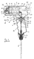
- the pipetting device shown in FIG. 1 has a housing 1 in which a cylinder 2 is provided.
- a piston 3 is guided in a longitudinally displaceable manner in the cylinder 2.
- a suction line 4 leads to the cylinder 2 to a pipette holder 5, in which one Pipette 6 releasably attached, namely inserted.
- the pipette holder 5 is in one Inserted housing attachment 7, which is screwed onto the housing 1.
- the cylinder 2 consists of a cylinder part 8 and a head part 9. It is from Cylinder brackets 10, 11 bordered, which are connected to the housing 1.
- the piston 3, which is longitudinally displaceable in the cylinder 2, is cup-shaped.
- the end part of the piston 3 is connected to a piston rod 12, on the latter the piston 3 facing away from a U-shaped extension 13 connects with an actuator 14 is connected.
- the actuating part 14 is a finger actuating part designed and has the shape of a trigger of a pistol. It is in guided a slot 15 of the housing 1 and so at a distance from a handle part 16 of the housing 1 arranged that one-handed operation is possible.
- the grip part 16 is gripped with the fist, with the fingers in the depressions of the grip part 16.
- the index finger can then the recessed grip 17 of the actuating part 14 pull in, i.e. move in the direction of arrow 18.
- One end of a compression spring is supported on the rear of the end part of the piston 3 19 from which surrounds the piston rod 12 and which in the cylindrical shoulder of the cup-shaped piston 3 is used.
- the other end of the compression spring 19 is at the Supported cylinder holder 11.
- the piston rod 12 is in a sleeve shape Approach 20 guided in the cylinder holder 11. With the piston rod 12 is one with her aligned extension 21 connected in a shoulder 22 of the housing 1st is guided and at the end of a plurality of graduated paragraphs 23 are provided, the various stops for the piston rod 12 and thus the stroke movement of the Form piston 3.
- a suction valve 24 designed as a beak valve is provided in the suction line 4. It is located in an extension 25 which is attached to the head part 9 of the cylinder 2 is molded. Furthermore, on cylinder 2 there is also a beak valve Pressure valve 26 is provided, which on another on the head part 9 of the cylinder 2 proposed approach is attached.
- a vent line 27 leads from the cylinder 2 to the outside.
- the vent line 27 opens into the cylinder 2 through the cylinder holder 11, namely the side of the piston facing away from the mouth of the suction line 4 into the cylinder 2 Third
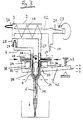
- a valve actuating lever 32 is provided, which is about an axis 33 is rotatably mounted.
- a first operating element 34 provided, through which the drain line 28 can be closed and can be opened, a second actuating element 35 through which the suction line 4 can be closed and opened, a third actuating element 36, through which the vent line 27 can be closed and opened, and a fourth actuating element 37, through which the discharge line 29 can be closed and opened is.
- the valve operating lever 32 has a first lever arm 38 and one second lever arm 39, which enclose an angle of approximately 90 ° between them.
- the first actuating element 34 and the second actuating element 35 are located at the end of the first lever arm 38.
- the actuating elements 34, 35 close an angle of about 90 °, the first lever arm 38 substantially in Direction of the bisector runs.
- the third actuating element is in an analogous manner 36 and the fourth actuating element 37 at the end of the second lever arm 39 arranged.
- the actuating elements 36, 37 close an angle of about 90 ° with each other, the second lever arm essentially in the direction the bisector runs.
- the suction line 4 can be closed at one point by the second actuating element 35 and controllable, that on the side facing away from the cylinder 2 of the branch the drain line 28 is.
- the discharge line 29 is through the fourth Actuating element 37 can be closed and opened at a point on the side of the branch of the discharge line 29 facing away from the cylinder 2.
- the valve actuation lever 32 is in the "suction" position. In this position, the drain line 28 is through the first actuating element 34 closed.
- the suction line 4 is opened by the second actuating element 35.
- the vent line 27 is opened by the third actuating element 36.
- the discharge line 29 is closed by the fourth actuating element 37.
- the pressure valve 26 closes and the suction valve 24 is opened.
- the Air is sucked into the cylinder 2 by the pipette 6 through the suction line 4. On the back of the piston 3, the air can flow out through the vent line 27.
- the liquid 40 is introduced into the pipette 6 to form a liquid column 41 sucked.
- the suction process can be repeated.
- the actuator 14 is released is, the compression spring 19 pushes the piston 3 against the direction of arrow 18 in the Starting position back.
- the suction valve 24 and closes opens the pressure valve 26.
- the air in the cylinder 2 escapes through the open Pressure valve 26. Air flows onto the through the open ventilation line 27 Back of the piston 3.
- the liquid column 41 remains unchanged. Subsequently a new suction process can be carried out through which the liquid column 41 continues to rise.
- the valve actuation lever 32 is in the "dispense” position. He was in this position by moving the lever arm 42 against the Force of the compression spring 43 fixed to the housing.
- the scale designation "0” denotes the position “suction”
- the scale designation "a” the position “discharge”
- the scale designation "b” the position "eject”. Positions a and b are achieved by manual actuation of the lever arm 42, by means of which the valve actuation lever 32 is rotated about the fulcrum or the axis of rotation 33.
- the drain line 28 is through the first actuating element 34 has been opened.
- the suction line 4 is through second actuating element 35 is still open.
- the vent line 27 is still opened by the third actuating element 36.
- the exhaust line 29 has been opened by the fourth actuating element 37. All actuators control the associated line.
- air flows into the pipette. Because the drain line 28 leads outside, a pressure equalization is created, through which the liquid flows out of the pipette 6 downwards. Air also flows through the vent line 27 and the ejection line 29 into the pipette. Because the vent line 27 also leads to the outside, i.e. is connected to the ambient pressure, too this removes the liquid from the pipette 6.
- the valve actuation lever 32 is in the "eject" position.
- the valve actuation lever 32 is therefore still further against the axis of rotation 33 has been rotated clockwise so that the lever arm 42 the scale designation b has reached.
- the drain line 28 is through the first actuating element 34 is still open.
- the suction line 4 is through the second actuator 35 has been closed.
- the vent line 27 has been closed by the third actuating element 36.
- the exhaust line 29 has remained open by the fourth actuating element 37.
- valve actuation lever 32 schematically shows the switching positions of the valve actuation lever 32 and the actuating elements thereon in their interaction with the different lines.
- the valve actuation lever 32 is located in the "suction” position, in Fig. 5b in the “discharge” position and in Fig. 5c in the Blow out position.
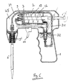
- Fig. 6 shows a modified embodiment, which is essentially that corresponds to Fig. 1.
- the pipette holder 5 ' is not below the handle part 16 arranged, but at the lower end of a bend 45 of the housing 1, the connects to the head part 9 of the cylinder 2 and from there to the front and down runs. Accordingly, the common line 31 is around the cylinder 2 led to the pipette holder 5 '.
Landscapes
- Health & Medical Sciences (AREA)
- Clinical Laboratory Science (AREA)
- Chemical & Material Sciences (AREA)
- Chemical Kinetics & Catalysis (AREA)
- Sampling And Sample Adjustment (AREA)
- Devices For Use In Laboratory Experiments (AREA)
Claims (8)
- Pipette pour l'aspiration et l'amenée d'un liquide dans une pipette (6) comportant un boítier (1), un réceptacle (5) pour une pipette (6), un cylindre (2) dans lequel un piston (3) est guidé de manière à pouvoir se déplacer en longitudinale, qui est relié à une tige de piston (12) se projetant hors du cylindre, tige de piston à laquelle une pièce d'actionnement (14) est prévue, comportant par ailleurs une conduite d'aspiration (4) allant du réceptacle de la pipette (5) au cylindre (2), une soupape d'aspiration (24) étant prévue dans la conduite d'aspiration (4), de préférence une valve à bec,
caractérisée en ce qu'à partir de la conduite d'aspiration (4) une conduite de décharge (28) conduisant à l'air libre dévie, qui peut être fermée et ouverte par un élément d'actionnement (34),
que la conduite d'aspiration (4) peut être fermée ou ouverte par un deuxième élément d'actionnement (35) à un autre endroit qui se trouve du côté détourné du cylindre (2) de la déviation de la conduite de décharge (28),
qu'une conduite de purge (27) est prévue qui conduit du cylindre (2) à l'air libre, qui débouche dans le cylindre (2) du côté du piston (3) détourné de l'embouchure de la conduite d'aspiration (4) dans le cylindre (2) et qui peut être fermée et ouverte par un troisième élément d'actionnement (36) et qu'une conduite d'éjection (29) est prévue qui dévie de la conduite de purge (27) et conduit au réceptacle de la pipette (5) et qui peut être fermée et ouverte par un quatrième élément d'actionnement (37) à un endroit qui se trouve du côté opposé au cylindre (2) de la déviation de la conduite d'éjection (29). - Pipette selon la revendication 1, caractérisée en ce que le piston (3) est exposé à la pression d'un ressort (19).
- Pipette selon les revendications 1 ou 2, caractérisée en ce que le mouvement du piston est limité par une butée, de préférence par une butée (23) modifiable.
- Pipette selon l'une quelconque des revendications précédentes, caractérisée en ce qu'une soupape de refoulement (26), de préférence une valve à bec, est prévue sur le cylindre (2).
- Pipette selon l'une quelconque des revendications précédentes, caractérisée en ce que le premier élément d'actionnement (34) et le second élément d'actionnement (35) sont prévus sur un levier d'actionnement de soupape (32).
- Pipette selon la revendication 5, caractérisée en ce que le levier d'actionnement de soupape (32) est logé dans le boítier (1) de manière à pouvoir tourner.
- Pipette selon l'une quelconque des revendications précédentes, caractérisée en ce que le troisième élément d'actionnement (36) et le quatrième élément d'actionnement (37) sont prévus sur un levier d'actionnement de soupape (32), de préférence sur le levier d'actionnement de soupape (32) comportant le premier élément d'actionnement (34) et le second élément d'actionnement (35).
- Pipette selon la revendication 7, caractérisée en ce que le levier d'actionnement de soupape (32) est logé dans le boítier (1) de manière à pouvoir tourner.
Applications Claiming Priority (2)
| Application Number | Priority Date | Filing Date | Title |
|---|---|---|---|
| DE1997117361 DE19717361C3 (de) | 1997-04-24 | 1997-04-24 | Pipettiergerät |
| DE19717361 | 1997-04-24 |
Publications (3)
| Publication Number | Publication Date |
|---|---|
| EP0873790A2 EP0873790A2 (fr) | 1998-10-28 |
| EP0873790A3 EP0873790A3 (fr) | 1999-09-08 |
| EP0873790B1 true EP0873790B1 (fr) | 2003-08-13 |
Family
ID=7827642
Family Applications (1)
| Application Number | Title | Priority Date | Filing Date |
|---|---|---|---|
| EP98102445A Expired - Lifetime EP0873790B1 (fr) | 1997-04-24 | 1998-02-12 | Pipette |
Country Status (2)
| Country | Link |
|---|---|
| EP (1) | EP0873790B1 (fr) |
| DE (2) | DE19717361C3 (fr) |
Families Citing this family (1)
| Publication number | Priority date | Publication date | Assignee | Title |
|---|---|---|---|---|
| US7093507B2 (en) * | 2003-05-12 | 2006-08-22 | Bel-Art Products, Inc. | Pipette control arrangement |
Family Cites Families (11)
| Publication number | Priority date | Publication date | Assignee | Title |
|---|---|---|---|---|
| FR1025614A (fr) * | 1950-09-12 | 1953-04-17 | Pipette volumétrique | |
| DE1719579U (de) * | 1955-11-14 | 1956-03-29 | Wolfgang Sternberg | Pipettiergeraet. |
| DE1598531A1 (de) * | 1965-05-18 | 1969-10-02 | Heinz Herenz | Maschinell betriebenes Pipettiergeraet |
| DE2058836A1 (de) * | 1970-05-15 | 1971-11-25 | Bezirksinstitut Fuer Veterinae | Ventilanordnung an Pipettiervorrichtungen mit Saugball |
| US3954014A (en) * | 1974-12-16 | 1976-05-04 | Becton, Dickinson And Company | Multiple shot pipetter |
| US3963061A (en) * | 1975-09-16 | 1976-06-15 | Drummond Scientific Company | Apparatus for drawing liquids into, and expelling liquids from a pipette |
| US4257268A (en) * | 1979-08-24 | 1981-03-24 | Data Packaging Corporation | Pipetter |
| DE3818704A1 (de) * | 1988-06-01 | 1989-12-07 | Hirschmann Glasgeraete | Pipettiergeraet |
| US5073294A (en) * | 1990-03-07 | 1991-12-17 | Hercules Incorporated | Process of preparing compositions having multiple oriented mesogens |
| DE4014588A1 (de) * | 1990-05-07 | 1991-11-14 | Hirschmann Glasgeraete | Pipettiergeraet |
| DE4214634C1 (de) * | 1992-04-24 | 1993-10-07 | Deutsch & Neumann Gmbh | Pipettierhilfe |
-
1997
- 1997-04-24 DE DE1997117361 patent/DE19717361C3/de not_active Expired - Fee Related
-
1998
- 1998-02-12 EP EP98102445A patent/EP0873790B1/fr not_active Expired - Lifetime
- 1998-02-12 DE DE59809246T patent/DE59809246D1/de not_active Expired - Lifetime
Also Published As
| Publication number | Publication date |
|---|---|
| DE19717361A1 (de) | 1998-10-29 |
| DE19717361C3 (de) | 2002-08-22 |
| DE59809246D1 (de) | 2003-09-18 |
| DE19717361C2 (de) | 1999-06-24 |
| EP0873790A3 (fr) | 1999-09-08 |
| EP0873790A2 (fr) | 1998-10-28 |
Similar Documents
| Publication | Publication Date | Title |
|---|---|---|
| DE2645089C3 (de) | Ausgabemechanismus für in einem Behälter enthaltende Substanzen | |
| DE69402025T2 (de) | Spielzeugwaffe mit automatischem Kugelzuführsystem | |
| DE2737680C3 (de) | Spritzpistole | |
| DE69202937T2 (de) | Handbetätigte Sprühvorrichtung mit einem Betätigungshebel. | |
| DE670275T1 (de) | Dichtverschliessbare Abgabevorrichtung für einen Druck- oder Pumpbehälter. | |
| DE9111192U1 (de) | Auftragsvorrichtung mit Stiftübertragungstechnik | |
| DE7706406U1 (de) | Vorrichtung fuer die abgabe von fluessigkeiten | |
| DE2265393B1 (de) | Fluessigkeitsspruehvorrichtung | |
| EP1912745B1 (fr) | Dispositif de pulverisation de liquides pigmentes | |
| DE202011050102U1 (de) | Spritzmittelleiteinrichtung für eine Spritzpistole sowie Spritzpistole mit einer Spritzmittelleiteinrichtung | |
| DE69911474T2 (de) | Pipette mit vorrichtung zum abwerfen von pipettenspitzen | |
| DE2309547C3 (de) | Gerät zum Füllen und Entleeren eines Flüssigkeitsbehälters, z.B. einer Pipette | |
| EP1118313B1 (fr) | Pistolet pour pressuriser du ciment à os avec une seringue à ciment amovible | |
| DE69021364T2 (de) | Vorrichtung zur handhabung von biopsien und proben. | |
| DE19719669A1 (de) | Applikator | |
| EP3680017A1 (fr) | Pipette destinée à une utilisation avec une pointe de pipette | |
| DE19717361C2 (de) | Pipettiergerät | |
| CH631560A5 (en) | Metering device for liquids | |
| DE9210619U1 (de) | Zerstäuber mit Abzughebel, der mit elastischen Rückstellfortsätzen versehen ist | |
| DE2656238C3 (de) | Dampfbügeleisen | |
| DE19753146A1 (de) | Ausgabegerät für Kartuschen | |
| DE4010793C2 (de) | Vorrichtung zum Betätigen eines an einem Heizkörper einer Warmwasser-Heizungsanlage angeordneten Entlüftungsventils | |
| EP1660239B1 (fr) | Systeme pour remplir des contenants de stockage a partir d'appareils de distribution | |
| EP1195200A2 (fr) | Pipette avec un piston mouvant à la vitesse uniforme | |
| EP0221526A2 (fr) | Appareil pour remplir les cavités dentaires |
Legal Events
| Date | Code | Title | Description |
|---|---|---|---|
| PUAI | Public reference made under article 153(3) epc to a published international application that has entered the european phase |
Free format text: ORIGINAL CODE: 0009012 |
|
| 17P | Request for examination filed |
Effective date: 19980317 |
|
| AK | Designated contracting states |
Kind code of ref document: A2 Designated state(s): CH DE FR GB LI |
|
| AX | Request for extension of the european patent |
Free format text: AL;LT;LV;MK;RO;SI |
|
| PUAL | Search report despatched |
Free format text: ORIGINAL CODE: 0009013 |
|
| AK | Designated contracting states |
Kind code of ref document: A3 Designated state(s): AT BE CH DE DK ES FI FR GB GR IE IT LI LU MC NL PT SE |
|
| AX | Request for extension of the european patent |
Free format text: AL;LT;LV;MK;RO;SI |
|
| AKX | Designation fees paid |
Free format text: CH DE FR GB LI |
|
| 17Q | First examination report despatched |
Effective date: 20010918 |
|
| GRAH | Despatch of communication of intention to grant a patent |
Free format text: ORIGINAL CODE: EPIDOS IGRA |
|
| GRAH | Despatch of communication of intention to grant a patent |
Free format text: ORIGINAL CODE: EPIDOS IGRA |
|
| GRAA | (expected) grant |
Free format text: ORIGINAL CODE: 0009210 |
|
| AK | Designated contracting states |
Designated state(s): CH DE FR GB LI |
|
| PG25 | Lapsed in a contracting state [announced via postgrant information from national office to epo] |
Ref country code: FR Free format text: LAPSE BECAUSE OF NON-PAYMENT OF DUE FEES Effective date: 20030813 |
|
| REG | Reference to a national code |
Ref country code: GB Ref legal event code: FG4D Free format text: NOT ENGLISH |
|
| REG | Reference to a national code |
Ref country code: CH Ref legal event code: EP |
|
| REF | Corresponds to: |
Ref document number: 59809246 Country of ref document: DE Date of ref document: 20030918 Kind code of ref document: P |
|
| REG | Reference to a national code |
Ref country code: CH Ref legal event code: NV Representative=s name: ARNOLD & SIEDSMA AG |
|
| GBT | Gb: translation of ep patent filed (gb section 77(6)(a)/1977) |
Effective date: 20031118 |
|
| PGFP | Annual fee paid to national office [announced via postgrant information from national office to epo] |
Ref country code: CH Payment date: 20040225 Year of fee payment: 7 |
|
| PLBE | No opposition filed within time limit |
Free format text: ORIGINAL CODE: 0009261 |
|
| STAA | Information on the status of an ep patent application or granted ep patent |
Free format text: STATUS: NO OPPOSITION FILED WITHIN TIME LIMIT |
|
| 26N | No opposition filed |
Effective date: 20040514 |
|
| EN | Fr: translation not filed | ||
| PG25 | Lapsed in a contracting state [announced via postgrant information from national office to epo] |
Ref country code: LI Free format text: LAPSE BECAUSE OF NON-PAYMENT OF DUE FEES Effective date: 20050228 Ref country code: CH Free format text: LAPSE BECAUSE OF NON-PAYMENT OF DUE FEES Effective date: 20050228 |
|
| REG | Reference to a national code |
Ref country code: CH Ref legal event code: PL |
|
| PGFP | Annual fee paid to national office [announced via postgrant information from national office to epo] |
Ref country code: DE Payment date: 20100121 Year of fee payment: 13 |
|
| REG | Reference to a national code |
Ref country code: DE Ref legal event code: R119 Ref document number: 59809246 Country of ref document: DE Effective date: 20110901 |
|
| PG25 | Lapsed in a contracting state [announced via postgrant information from national office to epo] |
Ref country code: DE Free format text: LAPSE BECAUSE OF NON-PAYMENT OF DUE FEES Effective date: 20110901 |
|
| PGFP | Annual fee paid to national office [announced via postgrant information from national office to epo] |
Ref country code: GB Payment date: 20140128 Year of fee payment: 17 |
|
| GBPC | Gb: european patent ceased through non-payment of renewal fee |
Effective date: 20150212 |
|
| PG25 | Lapsed in a contracting state [announced via postgrant information from national office to epo] |
Ref country code: GB Free format text: LAPSE BECAUSE OF NON-PAYMENT OF DUE FEES Effective date: 20150212 |