EP0873805A1 - Cylindre de coulée et cage de laminoir - Google Patents
Cylindre de coulée et cage de laminoir Download PDFInfo
- Publication number
- EP0873805A1 EP0873805A1 EP98303018A EP98303018A EP0873805A1 EP 0873805 A1 EP0873805 A1 EP 0873805A1 EP 98303018 A EP98303018 A EP 98303018A EP 98303018 A EP98303018 A EP 98303018A EP 0873805 A1 EP0873805 A1 EP 0873805A1
- Authority
- EP
- European Patent Office
- Prior art keywords
- roll
- shell
- casting
- core
- cooling channels
- Prior art date
- Legal status (The legal status is an assumption and is not a legal conclusion. Google has not performed a legal analysis and makes no representation as to the accuracy of the status listed.)
- Withdrawn
Links
Images



Classifications
-
- B—PERFORMING OPERATIONS; TRANSPORTING
- B22—CASTING; POWDER METALLURGY
- B22D—CASTING OF METALS; CASTING OF OTHER SUBSTANCES BY THE SAME PROCESSES OR DEVICES
- B22D11/00—Continuous casting of metals, i.e. casting in indefinite lengths
- B22D11/06—Continuous casting of metals, i.e. casting in indefinite lengths into moulds with travelling walls, e.g. with rolls, plates, belts, caterpillars
- B22D11/0637—Accessories therefor
- B22D11/068—Accessories therefor for cooling the cast product during its passage through the mould surfaces
- B22D11/0682—Accessories therefor for cooling the cast product during its passage through the mould surfaces by cooling the casting wheel
Definitions
- This invention relates to a casting roll and roll stand, in particular, to an improved design of the casting rolls.
- Twin roll casting is an established technology for the production of metal strip.
- the thickness of the cast strip In the case of aluminium alloys, it is usual for the thickness of the cast strip to be in the range 6 - 10mm.
- molten metal is fed by a refractory nozzle into the bite of a pair of internally cooled, counterrotating rolls. Because of the use of refractory feeder tip the strip does not cover the full width of the roll, this causes localisation of the heat which causes thermal distortions in the roll which make it difficult to control dimensions of the strip being cast and also leads to defects arising in the roll which means that a relatively short working time for the roll and frequent roll changes are required.
- the caster rolls typically comprise a core and a shell which is commonly shrunk onto the core with an interference fit.
- the cooling channels which can be circumferential or axial are machined into the surface of the roll core and are connected to the water feed and return lines.
- the casting shells are typically 50 - 100mm thick and it is normal to periodically re-machine the surface to remove defects, for example defects known as heat checks.
- Heat check is characterised by the generation of a large number of fine cracks which result from contact with molten metal and the cyclic thermal and mechanical loading cycle the roll surface undergoes.
- the molten metal solidifies in contact with the casting rolls and then typically undergoes a hot reduction before exiting the caster as solid strip.
- a major problem of the aforesaid process is the tendency of the cast strip to adhere to either or both of the casting rolls. It is known that the application of a parting agent, such as a suspension of colloidal graphite in water, to the casting rolls on the exit side of the machine is beneficial in reducing this sticking.
- the parting agent is usually applied to the casting rolls as an atomised spray.
- a more serious problem occurs at the interface between the casting roll shell and the casting roll core. If material at this interface is damaged it is possible that the intimate contact between the shell and the core will be diminished locally with the result that the shell is not adequately supported. Moreover if the intimate contact is reduced the transfer of heat between the shell and the core and between the shell and the cooling water will be adversely affected. The combined effect of these various factors is the occurrence of localised sheet defects. This problem is not always immediately apparent but becomes more noticeable as the thickness of the cast shell is reduced and is characterised by localised gauge variations in the cast sheet in the vicinity of regions of the shell where material has previously stuck.
- US 5469909 describes a typical casting roll used in the roll casting of steel with a core and a relatively thin shell with cooling channels in the shell, and intimate contact at the interface of the core and the shell, however this intimate contact can only be achieved by diffusion bonding of the shell to the core by means of this specialised process which is time consuming and very expensive and does not permit the shell to be easily removed to be replaced in close proximity to the casting line.
- Such a means of bonding the shell to the roll would not be able to withstand the loads during aluminium casting. Due to the different method of operation employed when casting aluminium alloys, much greater loads are applied and the shell would separate from the roll and fail after a very short time.
- the present invention is aimed principally at overcoming the problems caused by the rolling action of the back up rolls on any material that passes through the casting roll/back up roll bite, but is applicable to all roll casters.
- a casting roll and casting roll stand comprising an inner core and an outer roll shell and cooling channels to permit liquid coolant to flow through the roll to cool the roll during casting, the shell being in intimate contact with the core and removably affixed thereto by an interference fit, characterised in that interference fit is at least 0.5 mm per metre of inner core diameter and the cooling channels are located within the roll shell.
- the cooling channels may alternatively or additional be located in the roll core.
- cooling channels are arranged axially along the length of the roll.
- the cooling channels may be grouped together and connected to a coolant supply sop that the direction of coolant flow can be reversed.
- cooling channels 3 are machined into the surface of the core.
- the shell 1 is typically arranged to be relatively thick compared to a steel casting roll in order to with stand the mechanical loads during aluminium casting.
- the cooling channels 3 are in the form of square cross sectional channels which are easy to machine into the core 2 before the shell 1 is fitted onto the core to form the roll.
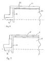
- a plurality of cooling holes 13 are provided which are circular in cross section and which are located in the shell 11 as shown in figures 2 and 7.
- the cooling holes 13 are provided longitudinally in the shell 11 spaced equidistantly around the circumference of the shell and at a constant distance from the internal surface 11a of the shell.
- the shell 11 is secured to the core 12 by means of an interference fit.
- the interference fit is of the order of 1 mm per metre of roll diameter in order to provide a sufficiently secure fitting of the core 12 and the shell 11 to withstand the high torque and loads experienced in particular in aluminium casting. If the shell 11 is not sufficiently securely attached to the core, the cyclical thermal and mechanical loading can result in movement of the shell with respect to the core.
- walking This relative movement is sometimes referred to as "walking".
- the only means of effectively preventing this effect or reducing it to an acceptable degree is by an interference fit of the order of lmm per meter of roll diameter. Any less than this and the walking effect is not reduced enough to prevent permanent damage to the roll to occur.
- cooling channels are conveniently located away from the interface between the shell and the core they could also be located at the interface. In this event the cooling channels could conveniently have a rectangular cross section or some other preferred shape.
- the casting roll of this first embodiment has the following dimensions: Roll diameter OD 600 mm Core diameter OD 440 mm Shell thickness 80 mm Cooling holes 20 mm dia. holes on a p.c.d of 480mm Cooling hole spacing 20 mm Interference 0.44 mm
- the thickness of shell between the holes and the outside diameter of the shell would be 50mm and as with conventional aluminium caster rolls would have a useable thickness of approximately 25mm.
- the axial cooling holes 13 are conveniently machined the complete length of the shell 11 and are connected to a cooling water feed and return lines 16 by means of a plenum chamber 14 at each end of the roll as shown in figure 8. On this basis the cooling water would enter the roll at one end and exit at the other.
- cooling holes 13 could be arranged in groups such that the direction of flow of the cooling water was reversed. This is shown schematically in Figure 3.
- FIG. 4 A further embodiment of the invention for the construction of the casting roll is shown in figures 4 and 6 in which the cooling channels 23 are located in the core 22 of the roll and in this case it is preferred to locate the cooling holes 23 which are conveniently in the form of a series of axial holes some distance below the surface 22a of the core 22.
- the dimensions of the casting roll according to the embodiments of the invention roll should fall within the following ranges: Roll diameter OD 550 to 1200 mm Core diameter OD 310 to 1100 mm Shell thickness 50 to 120 mm Cooling holes to 60 mm from the interface. 10 to 30 mm dia. holes on a p.c.d. of 20 Cooling hole spacing 10 to 30 mm Interference 0.5 to 1.5 mm per metre of roll diameter.
- the above range for the location of the cooling holes 20 to 60 mm from the interface of the core and shell is for cooling holes arranged in the core.
- for cooling holes arranges in the shell the range is 0 to 60 mm.
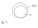
- the velocity of the water in the cooling channels can conveniently be increased by reducing the effective cross section of the cooling channels. This can be achieved by, for example inserting suitably sized rods 31 into each of the cooling holes 13, 23 as shown in Figure 5. The precise location of the rods and if necessary diameter of the rods can be selected to optimise heat transfer into the cooling water.
Landscapes
- Engineering & Computer Science (AREA)
- Mechanical Engineering (AREA)
- Continuous Casting (AREA)
- Rolls And Other Rotary Bodies (AREA)
Applications Claiming Priority (2)
| Application Number | Priority Date | Filing Date | Title |
|---|---|---|---|
| GB9710663 | 1997-04-24 | ||
| GBGB9710663.7A GB9710663D0 (en) | 1997-04-24 | 1997-04-24 | A casting roll and roll stand |
Publications (1)
| Publication Number | Publication Date |
|---|---|
| EP0873805A1 true EP0873805A1 (fr) | 1998-10-28 |
Family
ID=10812940
Family Applications (1)
| Application Number | Title | Priority Date | Filing Date |
|---|---|---|---|
| EP98303018A Withdrawn EP0873805A1 (fr) | 1997-04-24 | 1998-04-20 | Cylindre de coulée et cage de laminoir |
Country Status (3)
| Country | Link |
|---|---|
| EP (1) | EP0873805A1 (fr) |
| BR (1) | BR9801456A (fr) |
| GB (1) | GB9710663D0 (fr) |
Cited By (4)
| Publication number | Priority date | Publication date | Assignee | Title |
|---|---|---|---|---|
| WO2002026425A1 (fr) * | 2000-09-27 | 2002-04-04 | Sms Demag Aktiengesellschaft | Rouleau de coulee destine a la formation d'une barre de coulee, en particulier pour une machine de coulee a deux rouleaux |
| WO2002096583A1 (fr) * | 2001-05-29 | 2002-12-05 | Danieli & C. Officine Meccaniche Spa | Cristalliseur a rouleaux pour une machine de coulee continue |
| EP2682203A3 (fr) * | 2012-07-04 | 2018-02-28 | Aktiebolaget SKF | Élément de blocage, ligne de rouleau et appareil de coulée continue |
| WO2023000522A1 (fr) * | 2021-07-21 | 2023-01-26 | 安泰非晶科技有限责任公司 | Rouleau de refroidissement et son procédé d'ajustement |
Families Citing this family (1)
| Publication number | Priority date | Publication date | Assignee | Title |
|---|---|---|---|---|
| CN113560512B (zh) * | 2021-08-02 | 2022-04-26 | 常州宝菱重工机械有限公司 | 连铸辊及其装配方法 |
Citations (5)
| Publication number | Priority date | Publication date | Assignee | Title |
|---|---|---|---|---|
| US2850776A (en) * | 1956-12-03 | 1958-09-09 | Hunter Eng Co | Roll constructions for continuous casting machines |
| US3834205A (en) * | 1972-12-20 | 1974-09-10 | Procter & Gamble | Selectively insulated mill roll |
| JPS5741811A (en) * | 1980-08-26 | 1982-03-09 | Kobe Steel Ltd | Sleeve type composite roll |
| DE3839110A1 (de) * | 1987-11-19 | 1989-06-01 | Hitachi Ltd | Zwillingswalzen-stranggiesseinrichtung |
| WO1993019874A1 (fr) * | 1992-03-30 | 1993-10-14 | Ab Dalforsån | Rouleau porteur refroidi |
-
1997
- 1997-04-24 GB GBGB9710663.7A patent/GB9710663D0/en not_active Ceased
-
1998
- 1998-04-20 EP EP98303018A patent/EP0873805A1/fr not_active Withdrawn
- 1998-04-24 BR BR9801456-0A patent/BR9801456A/pt not_active Application Discontinuation
Patent Citations (5)
| Publication number | Priority date | Publication date | Assignee | Title |
|---|---|---|---|---|
| US2850776A (en) * | 1956-12-03 | 1958-09-09 | Hunter Eng Co | Roll constructions for continuous casting machines |
| US3834205A (en) * | 1972-12-20 | 1974-09-10 | Procter & Gamble | Selectively insulated mill roll |
| JPS5741811A (en) * | 1980-08-26 | 1982-03-09 | Kobe Steel Ltd | Sleeve type composite roll |
| DE3839110A1 (de) * | 1987-11-19 | 1989-06-01 | Hitachi Ltd | Zwillingswalzen-stranggiesseinrichtung |
| WO1993019874A1 (fr) * | 1992-03-30 | 1993-10-14 | Ab Dalforsån | Rouleau porteur refroidi |
Non-Patent Citations (1)
| Title |
|---|
| PATENT ABSTRACTS OF JAPAN vol. 006, no. 113 (M - 138) 24 June 1982 (1982-06-24) * |
Cited By (5)
| Publication number | Priority date | Publication date | Assignee | Title |
|---|---|---|---|---|
| WO2002026425A1 (fr) * | 2000-09-27 | 2002-04-04 | Sms Demag Aktiengesellschaft | Rouleau de coulee destine a la formation d'une barre de coulee, en particulier pour une machine de coulee a deux rouleaux |
| WO2002096583A1 (fr) * | 2001-05-29 | 2002-12-05 | Danieli & C. Officine Meccaniche Spa | Cristalliseur a rouleaux pour une machine de coulee continue |
| US6883585B2 (en) | 2001-05-29 | 2005-04-26 | Danieli & C. Officine Meccaniche Spa | Crystallizer with rollers for a continuous casting machine |
| EP2682203A3 (fr) * | 2012-07-04 | 2018-02-28 | Aktiebolaget SKF | Élément de blocage, ligne de rouleau et appareil de coulée continue |
| WO2023000522A1 (fr) * | 2021-07-21 | 2023-01-26 | 安泰非晶科技有限责任公司 | Rouleau de refroidissement et son procédé d'ajustement |
Also Published As
| Publication number | Publication date |
|---|---|
| GB9710663D0 (en) | 1997-07-16 |
| BR9801456A (pt) | 1999-09-28 |
Similar Documents
| Publication | Publication Date | Title |
|---|---|---|
| KR100756768B1 (ko) | 스트립 재료를 공급하기 위한 핀치 롤 조립체 | |
| US5887644A (en) | Roll cooling structure for twin roll continuous caster | |
| CN107000043B (zh) | 用于通过控制辊凸度而连续地铸造铸带的方法和装置 | |
| KR102469642B1 (ko) | 크라운 제어 기능을 갖는 금속 스트립 주조 방법 | |
| JPH01133642A (ja) | 双ロール式連続鋳造装置 | |
| JPH0620614B2 (ja) | 急冷金属薄帯製造用の冷却ロ−ル | |
| GB2324488A (en) | A casting roll with an interference fit between its inner core and outer shell | |
| US20220373033A1 (en) | Bearing box for rotating roller, method for cooling bearing box for rotating roller, steel continuous casting machine, and steel continuous casting method | |
| MXPA98003204A (en) | Roller of molding and support with rodi | |
| US7594535B2 (en) | Twin roll caster, and equipment and method for operating the same | |
| JP3259639B2 (ja) | 強冷却型プラグおよびその冷却方法 | |
| JP2820812B2 (ja) | 双ロール式連続鋳造機の冷却ロール | |
| JPH09150249A (ja) | 連続鋳造機の2次冷却帯用ロールおよび連続鋳造方法 | |
| JP5017901B2 (ja) | 熱間圧延方法及び装置 | |
| JP4760403B2 (ja) | サーマルクラウン制御装置、圧延機及びその圧延機を用いた金属帯の製造方法 | |
| EP2680990B1 (fr) | Procédé pour allonger la durée de vie d'une ligne de laminage | |
| JP3223914B2 (ja) | 丸ビレットの冷却方法 | |
| KR100916063B1 (ko) | 선재 압연용 공형롤 냉각장치 | |
| JPH03110049A (ja) | 連続鋳造用分割ロールの軸受装置 | |
| AU2001268826B2 (en) | Feeding strip material | |
| JP3749611B2 (ja) | 熱間圧延機のワークロール冷却方法 | |
| KR200333731Y1 (ko) | 회전 불량 롤의 강제 구동용 더미 바 | |
| JP3298049B2 (ja) | 熱間粗圧延機用のワークロール | |
| JP2003001304A (ja) | コールドピルガー圧延機ガイド一体化冷却装置 | |
| JPS59163057A (ja) | 急冷金属薄帯の製造方法および冷却ロ−ル |
Legal Events
| Date | Code | Title | Description |
|---|---|---|---|
| PUAI | Public reference made under article 153(3) epc to a published international application that has entered the european phase |
Free format text: ORIGINAL CODE: 0009012 |
|
| AK | Designated contracting states |
Kind code of ref document: A1 Designated state(s): AT BE CH CY DE DK ES FI FR GB GR IE IT LI LU MC NL PT SE |
|
| AX | Request for extension of the european patent |
Free format text: AL;LT;LV;MK;RO;SI |
|
| AKX | Designation fees paid | ||
| STAA | Information on the status of an ep patent application or granted ep patent |
Free format text: STATUS: THE APPLICATION IS DEEMED TO BE WITHDRAWN |
|
| 18D | Application deemed to be withdrawn |
Effective date: 19990429 |