EP0873818A2 - Dispositif pour positionner correctement avec fixation par un seul nipple - Google Patents
Dispositif pour positionner correctement avec fixation par un seul nipple Download PDFInfo
- Publication number
- EP0873818A2 EP0873818A2 EP98107223A EP98107223A EP0873818A2 EP 0873818 A2 EP0873818 A2 EP 0873818A2 EP 98107223 A EP98107223 A EP 98107223A EP 98107223 A EP98107223 A EP 98107223A EP 0873818 A2 EP0873818 A2 EP 0873818A2
- Authority
- EP
- European Patent Office
- Prior art keywords
- pins
- pallet
- quick release
- release cylinder
- lid
- Prior art date
- Legal status (The legal status is an assumption and is not a legal conclusion. Google has not performed a legal analysis and makes no representation as to the accuracy of the status listed.)
- Granted
Links
Images


Classifications
-
- B—PERFORMING OPERATIONS; TRANSPORTING
- B23—MACHINE TOOLS; METAL-WORKING NOT OTHERWISE PROVIDED FOR
- B23Q—DETAILS, COMPONENTS, OR ACCESSORIES FOR MACHINE TOOLS, e.g. ARRANGEMENTS FOR COPYING OR CONTROLLING; MACHINE TOOLS IN GENERAL CHARACTERISED BY THE CONSTRUCTION OF PARTICULAR DETAILS OR COMPONENTS; COMBINATIONS OR ASSOCIATIONS OF METAL-WORKING MACHINES, NOT DIRECTED TO A PARTICULAR RESULT
- B23Q3/00—Devices holding, supporting, or positioning work or tools, of a kind normally removable from the machine
- B23Q3/18—Devices holding, supporting, or positioning work or tools, of a kind normally removable from the machine for positioning only
-
- B—PERFORMING OPERATIONS; TRANSPORTING
- B23—MACHINE TOOLS; METAL-WORKING NOT OTHERWISE PROVIDED FOR
- B23Q—DETAILS, COMPONENTS, OR ACCESSORIES FOR MACHINE TOOLS, e.g. ARRANGEMENTS FOR COPYING OR CONTROLLING; MACHINE TOOLS IN GENERAL CHARACTERISED BY THE CONSTRUCTION OF PARTICULAR DETAILS OR COMPONENTS; COMBINATIONS OR ASSOCIATIONS OF METAL-WORKING MACHINES, NOT DIRECTED TO A PARTICULAR RESULT
- B23Q1/00—Members which are comprised in the general build-up of a form of machine, particularly relatively large fixed members
- B23Q1/0063—Connecting non-slidable parts of machine tools to each other
- B23Q1/0072—Connecting non-slidable parts of machine tools to each other using a clamping opening for receiving an insertion bolt or nipple
-
- B—PERFORMING OPERATIONS; TRANSPORTING
- B23—MACHINE TOOLS; METAL-WORKING NOT OTHERWISE PROVIDED FOR
- B23Q—DETAILS, COMPONENTS, OR ACCESSORIES FOR MACHINE TOOLS, e.g. ARRANGEMENTS FOR COPYING OR CONTROLLING; MACHINE TOOLS IN GENERAL CHARACTERISED BY THE CONSTRUCTION OF PARTICULAR DETAILS OR COMPONENTS; COMBINATIONS OR ASSOCIATIONS OF METAL-WORKING MACHINES, NOT DIRECTED TO A PARTICULAR RESULT
- B23Q7/00—Arrangements for handling work specially combined with or arranged in, or specially adapted for use in connection with, machine tools, e.g. for conveying, loading, positioning, discharging, sorting
- B23Q7/14—Arrangements for handling work specially combined with or arranged in, or specially adapted for use in connection with, machine tools, e.g. for conveying, loading, positioning, discharging, sorting co-ordinated in production lines
- B23Q7/1426—Arrangements for handling work specially combined with or arranged in, or specially adapted for use in connection with, machine tools, e.g. for conveying, loading, positioning, discharging, sorting co-ordinated in production lines with work holders not rigidly fixed to the transport devices
Definitions
- the present invention relates to a device for clamping and correctly positioning pallets.
- the object of the present invention is therefore a Device of the type mentioned in this regard to train that a pallet with only one Retractable nipple in a precisely defined position on the assigned quick release cylinder placed on this can be attached.
- This anti-rotation device is in the form of locating pins, the one have appropriate mechanical strength.
- the anti-rotation lock can be of several types be trained.
- a first embodiment provides that the pallet with Pins are provided that are assigned to Place the stop surfaces of the quick release cylinder.
- Pins are provided that are assigned to Place the stop surfaces of the quick release cylinder.
- attach these pens it is also possible to attach these pens to attach the quick release cylinder and the Provide stop surfaces on the pallet.
- the number of pens depends on the Machining occurring torque. Depending on the size of the Torques can be two, four, six or even more of these Pins may be provided.
- the pins are provided to arrange for the anti-rotation so that a Possibility to swivel by 90 °, i.e. by one on the right Angle.
- Another embodiment provides that the arrangement of the Pins are made at 120 ° angles.
- the assigned Stop surfaces of the quick release cylinder are in this Case also sensibly arranged at 120 ° angles.
- the workpiece to be machined can be in this if necessary Angle division can be rotated.
- the anti-rotation device is designed in such a way that the pallet can be placed on the quick-release cylinder in several angular positions and can be held reliably in these angular positions. In some processing steps in particular, it may be necessary to first process the pallet in a first position, then to rotate it by a certain angle, to reattach it and then to process it again. By a suitable choice of the angular steps, the anti-rotation device can be held extremely precisely in relation to the quick-release cylinder according to the machining specifications. Any angle adjustments are possible.
- a major advantage of the system consisting of retractable nipple and Quick release cylinder is that the pallet itself in precisely defined position in relation to the machine tool is held. It is preferred if the pallet itself now suitable stop or contact surfaces for the or the has machining workpieces, so that they also, as soon as the pallet is clamped in precisely defined Position. A retrofit or adjustment to Compensating assembly tolerances can be avoided.
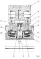
- Figures 1 and 2 show an embodiment of the present invention.
- a plate 1 with a or several quick release cylinders 2 with assigned Cover 3 provided.
- the lid 3 are each one Passed through nipple 4, which in turn in a Pallet 5 via a counter holder 6 and a threaded rod 7 is attached.
- the retractable nipple 4 is here with a Provided ring flange 8, which is in an associated Recess of the lid 3 creates and in this way Centering the retractable nipple and thus the associated one Pallet 5 ensures.
- the anti-rotation device between the pallet 5 and the Quick release cylinder 2 is shown in the Embodiment via a plurality of pins 10 which on the Pallet 5 are attached. These pens are made in high accuracy manufactured bores used and create assigned stop surfaces on the lid 3 of the Quick release cylinder. As already mentioned at the beginning, is the number of pins used 10 on the amount of Load dependent.
- the entire plate 1 can on a table 12 one Machine tool to be attached.
- the attachment can either, as shown, done via screws; but it can also be any other suitable mounting type can be used.
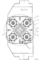
- Figures 3 and 4 show a special embodiment, in which the pins 19 of the on two of four sides Anti-rotation devices are designed eccentrically.
- the left pin 19 is shown so that the Eccentric is clearly recognizable.
- the right pin 10 is as ordinary round pen trained.
- To fix the Pallet 1 in this embodiment is sufficient if in a Rectangular, preferably viewed from the top view square arrangement, two not opposite each other arranged pins are eccentric.
- variable distance is important in this arrangement between the round pins 10 and the eccentric pins 19 which results from twisting the eccentric pins 19. This arrangement opens up the possibility of Anti-rotation device between pallet 1 and quick release cylinder 2 to adapt exactly to the dimensions of the components.
- FIGS. 5-9 A plate 1 is shown in FIGS. 5-9, which has five essentially identical quick release cylinders 2 is provided.
- the Plate 1 attached to the table 12 and in the direction of the arrow 13.14 rotatable.
- the blocking circle is in dashed lines indicated.
- the plate 1 can be fixed on the table 12 here either via dowel pins 15 with assigned screws respectively; but it is also possible to plate 1 again with one or more retractable nipples and this in assigned quick release cylinders of the table 12 record.
- the quick release cylinder 2 can be a schematically shown hydraulic connection with pressure oil be supplied to the retraction of the retractable nipple 4 cause.
- Figure 5 shows a view in which no pallets 5 are put on.
- the top two Quick release cylinder 2 each individually or with one shared pallet.
- the Diagonals are used; it is also possible to everyone Use quick release cylinder 2 individually.
- FIG. 6 shows an assembly of the Plate 1 with a total of four workpieces, the The middle place remains free. Each of these workpieces can thus on the three outer sides and on the top can be processed without having to reclamp. With it can also have a correspondingly small head also be possible to edit the inside.
- the plate 1 is e.g. in Direction of arrow 13 rotated by 90 °, whereupon the second workpiece is processed.
- the plate 1 can be turned by 180 ° by hand, too to edit the inside so far.
- different processing sequence can also be required be provided.
- Figure 7 shows workpieces in which such a rotation is not required.
- the difference compared to Figure 6 is that the inside is not processed like from the schematically illustrated holes according to FIG 6.7 results.
- FIGS. 6-8 enable significantly shorter transformation times. Especially in the Clamping according to Figures 7 and 8 can be done without any Span can be processed continuously. The changeover times of the The machine is reduced considerably.
- quick release cylinder 2 or the cover 3 By a suitable design of the quick release cylinder 2 or the cover 3 can thus be achieved that a single pallet with a single retractable nipple is held against rotation. At the same time, however, how So far, several quick release cylinders work together to create one single pallet to clamp.
Landscapes
- Engineering & Computer Science (AREA)
- Mechanical Engineering (AREA)
- Jigs For Machine Tools (AREA)
- Feeding Of Workpieces (AREA)
- Pallets (AREA)
- Picture Signal Circuits (AREA)
- Paper (AREA)
- Vehicle Body Suspensions (AREA)
Applications Claiming Priority (2)
| Application Number | Priority Date | Filing Date | Title |
|---|---|---|---|
| DE19716797A DE19716797A1 (de) | 1997-04-22 | 1997-04-22 | Lagerichtige Ein-Nippel-Einspannung |
| DE19716797 | 1997-04-22 |
Publications (3)
| Publication Number | Publication Date |
|---|---|
| EP0873818A2 true EP0873818A2 (fr) | 1998-10-28 |
| EP0873818A3 EP0873818A3 (fr) | 1999-04-07 |
| EP0873818B1 EP0873818B1 (fr) | 2003-04-02 |
Family
ID=7827274
Family Applications (1)
| Application Number | Title | Priority Date | Filing Date |
|---|---|---|---|
| EP98107223A Expired - Lifetime EP0873818B1 (fr) | 1997-04-22 | 1998-04-21 | Dispositif pour positionner correctement avec fixation par un seul nipple |
Country Status (5)
| Country | Link |
|---|---|
| US (1) | US6139002A (fr) |
| EP (1) | EP0873818B1 (fr) |
| JP (1) | JPH1110468A (fr) |
| AT (1) | ATE235990T1 (fr) |
| DE (2) | DE19716797A1 (fr) |
Cited By (3)
| Publication number | Priority date | Publication date | Assignee | Title |
|---|---|---|---|---|
| EP0936025A3 (fr) * | 1998-02-10 | 2002-04-17 | Stark Werkzeuggesellschaft mbH | Système de serrage avec cylindre de serrage et dispositif de serrage |
| EP1048397A3 (fr) * | 1999-04-17 | 2002-06-12 | Stark Werkzeuggesellschaft mbH | Fixation d'une cheville de connection d'une pièce ou d'une pallete porte-pièces |
| DE10317349B4 (de) * | 2003-04-15 | 2018-01-25 | Andreas Maier Gmbh & Co. Kg | Kombination aus einemSchnellspannzylinder und einer lagerichtig auf dem selben aufliegenden Werkstückpalette |
Families Citing this family (16)
| Publication number | Priority date | Publication date | Assignee | Title |
|---|---|---|---|---|
| US6186711B1 (en) * | 1998-04-03 | 2001-02-13 | Axxess Technologies, Inc. | Engraving system |
| DE19829955A1 (de) * | 1998-07-04 | 2000-01-05 | System 3R International Ab Vae | Verbinder zur Verwendung in einer Kupplungsvorrichtung |
| JP3338669B2 (ja) | 1999-08-03 | 2002-10-28 | 株式会社コスメック | データム機能付きクランプ装置 |
| JP2002361533A (ja) | 2001-06-07 | 2002-12-18 | Kosmek Ltd | データム機能付きクランプ装置 |
| EP1302278A1 (fr) | 2001-10-12 | 2003-04-16 | Kabushiki Kaisha Kosmek | Dispositif de serrage |
| DK1344599T3 (da) * | 2002-03-11 | 2004-10-04 | Erowa Ag | Spændindretning med en centrerpatron og en spændtap, som kan fastspændes deri |
| US20040018048A1 (en) * | 2002-07-26 | 2004-01-29 | Sausen Earl W. | Pneumatic docking system |
| US7165763B2 (en) * | 2002-12-27 | 2007-01-23 | Kosmek Ltd. | Positioning device |
| JP4336558B2 (ja) * | 2003-10-07 | 2009-09-30 | ヤマザキマザック株式会社 | 治具プレート |
| DE102004017911A1 (de) * | 2004-04-13 | 2005-11-03 | Bayerische Motoren Werke Ag | Verfahren und Vorrichtung zum Aufspannen eines Werkstücks |
| EP1693147A1 (fr) * | 2005-02-16 | 2006-08-23 | Cross Hüller GmbH | Machine-outil bibroche avec deux porte-pièces dont l'un est ajustable |
| DE502005003100D1 (de) * | 2005-07-09 | 2008-04-17 | 3R Syst Int Ab | Spannvorrichtung für ein Werkzeug oder ein Werkstück |
| TW200732083A (en) * | 2006-01-30 | 2007-09-01 | Tool Internat Ag F | Clamping apparatus |
| JP2008183651A (ja) * | 2007-01-29 | 2008-08-14 | Toyota Motor Corp | 段替えプレートのクランプ装置 |
| CN105751144B (zh) * | 2016-04-27 | 2017-10-31 | 中车青岛四方机车车辆股份有限公司 | 随行夹具与转台的安装系统 |
| US11478901B2 (en) * | 2020-06-04 | 2022-10-25 | Rimeco Products, Inc. | Pneumatic fixture clamp |
Family Cites Families (19)
| Publication number | Priority date | Publication date | Assignee | Title |
|---|---|---|---|---|
| US3986617A (en) * | 1975-07-14 | 1976-10-19 | Sundstrand Corporation | Indexing pallet carrier for machine tools |
| JPS5822232U (ja) * | 1981-08-04 | 1983-02-10 | 相生精機株式会社 | 工作機械へのクランプパレツト交換装置 |
| JPH0696217B2 (ja) * | 1986-04-30 | 1994-11-30 | 津田駒工業株式会社 | クランプ装置 |
| US4703916A (en) * | 1986-06-12 | 1987-11-03 | Shinn Fu Corporation | Hydraulic jack structural improvement in one-way hydraulic path in association with safety pressure relief network |
| DE3820870A1 (de) * | 1987-06-23 | 1989-05-24 | Forkardt Paul Gmbh | Einrichtung zum zentrieren einer wechselpalette bezueglich einer spannvorrichtungsachse und dafuer bestimmte positioniereinrichtung |
| DE3824824A1 (de) * | 1988-07-21 | 1990-01-25 | Hauni Werke Koerber & Co Kg | Vorrichtung zur positionierung von werkstuecken |
| JP2906058B2 (ja) * | 1988-08-23 | 1999-06-14 | 株式会社森精機製作所 | 工作機械のテーブル装置 |
| DE3902854A1 (de) * | 1989-02-01 | 1990-08-02 | Gedib Ingenieurbuero U Innovat | Fertigungseinrichtung mit wechselpaletten |
| DE3919077C1 (fr) * | 1989-06-10 | 1990-07-26 | Erowa Ag, Reinach, Ch | |
| IT1238059B (it) * | 1990-02-09 | 1993-06-26 | Salvagnini Transferica Spa Ora | Complesso di elementi di ancoraggio di tipo regolabile per componenti di attrezzature di bloccaggio di pezzi su un pallet di supporto |
| DE4010653A1 (de) * | 1990-04-03 | 1991-10-10 | Lebrecht Horst Dipl Ing Fh | Zentrierende spannvorrichtung |
| DE4116103A1 (de) * | 1991-05-17 | 1992-11-19 | Hirschmann Gmbh | Vorrichtung zum ankuppeln eines werkstueckes oder eines werkzeuges an einer werkzeugmaschine, insbesondere einer elektrode an einer funkenerosionsmaschine |
| DE9203992U1 (de) * | 1991-05-17 | 1992-05-21 | Hirschmann GmbH, 7239 Fluorn-Winzeln | Vorrichtung zum Ankuppeln eines Werkstückes oder eines Werkzeuges an eine Werkzeugmaschine, insbesondere einer Elektrode an eine Funkenerosionsmaschine |
| DE4135418A1 (de) * | 1991-10-26 | 1993-05-27 | Emil Stark Gmbh | Spannvorrichtung zum spannen einer aufspannplatte auf einer traegerplatte fuer bearbeitungsmaschinen |
| DE4307342C2 (de) * | 1993-03-09 | 1994-12-08 | Erowa Ag | Einrichtung zum positionsdefinierten Aufspannen eines Werkstücks am Arbeitsplatz einer Bearbeitungsmaschine |
| DE9307196U1 (de) * | 1993-05-12 | 1994-08-04 | Spreitzer, Johann, 78559 Gosheim | Vorrichtungseinheit für Mehrseitenbearbeitung von Werkstücken |
| DE4341743C2 (de) * | 1993-12-08 | 1998-01-29 | Emil Stark | Aufspannplatte für eine Spannvorrichtung mit Einzugsnippel und Verfahren zur Herstellung der Aufspannplatte |
| JPH0811031A (ja) * | 1994-06-29 | 1996-01-16 | Olympus Optical Co Ltd | パレットおよびパレットのチャック装置 |
| DE59611135D1 (de) * | 1996-01-15 | 2004-12-09 | Cianci Pasquale | Auflagetisch mit einer Spannvorrichtung |
-
1997
- 1997-04-22 DE DE19716797A patent/DE19716797A1/de not_active Withdrawn
-
1998
- 1998-04-20 US US09/063,158 patent/US6139002A/en not_active Expired - Fee Related
- 1998-04-21 DE DE59807690T patent/DE59807690D1/de not_active Expired - Fee Related
- 1998-04-21 EP EP98107223A patent/EP0873818B1/fr not_active Expired - Lifetime
- 1998-04-21 JP JP10110937A patent/JPH1110468A/ja active Pending
- 1998-04-21 AT AT98107223T patent/ATE235990T1/de not_active IP Right Cessation
Cited By (3)
| Publication number | Priority date | Publication date | Assignee | Title |
|---|---|---|---|---|
| EP0936025A3 (fr) * | 1998-02-10 | 2002-04-17 | Stark Werkzeuggesellschaft mbH | Système de serrage avec cylindre de serrage et dispositif de serrage |
| EP1048397A3 (fr) * | 1999-04-17 | 2002-06-12 | Stark Werkzeuggesellschaft mbH | Fixation d'une cheville de connection d'une pièce ou d'une pallete porte-pièces |
| DE10317349B4 (de) * | 2003-04-15 | 2018-01-25 | Andreas Maier Gmbh & Co. Kg | Kombination aus einemSchnellspannzylinder und einer lagerichtig auf dem selben aufliegenden Werkstückpalette |
Also Published As
| Publication number | Publication date |
|---|---|
| EP0873818A3 (fr) | 1999-04-07 |
| DE19716797A1 (de) | 1998-11-05 |
| JPH1110468A (ja) | 1999-01-19 |
| US6139002A (en) | 2000-10-31 |
| EP0873818B1 (fr) | 2003-04-02 |
| ATE235990T1 (de) | 2003-04-15 |
| DE59807690D1 (de) | 2003-05-08 |
Similar Documents
| Publication | Publication Date | Title |
|---|---|---|
| EP0873818B1 (fr) | Dispositif pour positionner correctement avec fixation par un seul nipple | |
| EP0985488B1 (fr) | Dispositif de serrage pour pièces multiples | |
| EP0198379B1 (fr) | Preneur à mâchoire de prise échangeable | |
| EP0742081A2 (fr) | Etan universel de précision pour une machine-outil | |
| EP1813381A1 (fr) | Dispositif de serrage doté d'un mandrin pour le serrage fixe d'un élément de serrage | |
| DE202013101917U1 (de) | Spannfutter | |
| EP0416610B1 (fr) | Porte-outil, notamment pour tours, avec porte-outil interchangeable | |
| DE3617119A1 (de) | Umsetzbare wendeschneidplatte | |
| DE102018119980A1 (de) | Spann- oder Greifeinrichtung | |
| EP0873816B1 (fr) | Cylindre pour positionnement et serrage rapide | |
| DE2840129C2 (de) | Vorrichtung zum Aufspannen eines Werkstückes auf einem Werkzeugmaschinentisch | |
| EP0761382B1 (fr) | Dispositif à positionner des pièces dans des dispositifs de serrage | |
| DE4118376A1 (de) | Spanneinrichtung | |
| DE2839320A1 (de) | Spannvorrichtung | |
| DE19716800A1 (de) | Werkstückspannung über Einzugsnippel | |
| DE3441968A1 (de) | Gegenstandsfeststeller, -aufspannvorrichtung und bearbeitungsverfahren | |
| DE29607499U1 (de) | Vorrichtung zur Feineinstellung von Anschlägen, Aufnahmebolzen, Konturpaßstücken u.dgl., an Spannvorrichtungen, insbesondere für Meß- und Werkzeugmaschinen | |
| DE3708363A1 (de) | Spannfutter fuer werkzeugmaschinen | |
| DE102005002093B3 (de) | Werkzeugträgersystem, insbesondere für Drehmaschinen oder dergleichen Werkzeugmaschinen | |
| DE102017007905A1 (de) | Festlegevorrichtung für Werkzeugmaschinen | |
| DE2943713C2 (de) | Halterung für Mischarme | |
| DE29723452U1 (de) | Lagerichtige Ein-Nippel-Einspannung | |
| DE9107104U1 (de) | Modulare Spannvorrichtung | |
| EP4029645B1 (fr) | Dispositif de serrage | |
| EP3366417A1 (fr) | Boulon de tension d'un système de serrage |
Legal Events
| Date | Code | Title | Description |
|---|---|---|---|
| PUAI | Public reference made under article 153(3) epc to a published international application that has entered the european phase |
Free format text: ORIGINAL CODE: 0009012 |
|
| AK | Designated contracting states |
Kind code of ref document: A2 Designated state(s): AT CH DE FR GB IT LI |
|
| AX | Request for extension of the european patent |
Free format text: AL;LT;LV;MK;RO;SI |
|
| PUAL | Search report despatched |
Free format text: ORIGINAL CODE: 0009013 |
|
| AK | Designated contracting states |
Kind code of ref document: A3 Designated state(s): AT BE CH CY DE DK ES FI FR GB GR IE IT LI LU MC NL PT SE |
|
| AX | Request for extension of the european patent |
Free format text: AL;LT;LV;MK;RO;SI |
|
| 17P | Request for examination filed |
Effective date: 19990930 |
|
| AKX | Designation fees paid |
Free format text: AT CH DE FR GB IT LI |
|
| RAP1 | Party data changed (applicant data changed or rights of an application transferred) |
Owner name: STARK WERKZEUGGESELLSCHAFT MBH |
|
| RIN1 | Information on inventor provided before grant (corrected) |
Inventor name: STARK WERKZEUGGESELLSCHAFT MBH |
|
| GRAG | Despatch of communication of intention to grant |
Free format text: ORIGINAL CODE: EPIDOS AGRA |
|
| RAP1 | Party data changed (applicant data changed or rights of an application transferred) |
Owner name: STARK SPANNSYSTEME GMBH |
|
| RIN1 | Information on inventor provided before grant (corrected) |
Inventor name: STARK SPANNSYSTEME GMBH |
|
| 17Q | First examination report despatched |
Effective date: 20020626 |
|
| GRAG | Despatch of communication of intention to grant |
Free format text: ORIGINAL CODE: EPIDOS AGRA |
|
| GRAG | Despatch of communication of intention to grant |
Free format text: ORIGINAL CODE: EPIDOS AGRA |
|
| GRAH | Despatch of communication of intention to grant a patent |
Free format text: ORIGINAL CODE: EPIDOS IGRA |
|
| GRAH | Despatch of communication of intention to grant a patent |
Free format text: ORIGINAL CODE: EPIDOS IGRA |
|
| GRAA | (expected) grant |
Free format text: ORIGINAL CODE: 0009210 |
|
| AK | Designated contracting states |
Designated state(s): AT CH DE FR GB IT LI |
|
| PG25 | Lapsed in a contracting state [announced via postgrant information from national office to epo] |
Ref country code: IT Free format text: LAPSE BECAUSE OF FAILURE TO SUBMIT A TRANSLATION OF THE DESCRIPTION OR TO PAY THE FEE WITHIN THE PRESCRIBED TIME-LIMIT;WARNING: LAPSES OF ITALIAN PATENTS WITH EFFECTIVE DATE BEFORE 2007 MAY HAVE OCCURRED AT ANY TIME BEFORE 2007. THE CORRECT EFFECTIVE DATE MAY BE DIFFERENT FROM THE ONE RECORDED. Effective date: 20030402 Ref country code: GB Free format text: LAPSE BECAUSE OF FAILURE TO SUBMIT A TRANSLATION OF THE DESCRIPTION OR TO PAY THE FEE WITHIN THE PRESCRIBED TIME-LIMIT Effective date: 20030402 Ref country code: FR Free format text: LAPSE BECAUSE OF FAILURE TO SUBMIT A TRANSLATION OF THE DESCRIPTION OR TO PAY THE FEE WITHIN THE PRESCRIBED TIME-LIMIT Effective date: 20030402 |
|
| REG | Reference to a national code |
Ref country code: GB Ref legal event code: FG4D Free format text: NOT ENGLISH |
|
| RIN1 | Information on inventor provided before grant (corrected) |
Inventor name: STARK, EMIL, JR |
|
| REG | Reference to a national code |
Ref country code: CH Ref legal event code: EP |
|
| REG | Reference to a national code |
Ref country code: CH Ref legal event code: NV Representative=s name: BOVARD AG PATENTANWAELTE |
|
| REF | Corresponds to: |
Ref document number: 59807690 Country of ref document: DE Date of ref document: 20030508 Kind code of ref document: P |
|
| GBV | Gb: ep patent (uk) treated as always having been void in accordance with gb section 77(7)/1977 [no translation filed] |
Effective date: 20030402 |
|
| PLBE | No opposition filed within time limit |
Free format text: ORIGINAL CODE: 0009261 |
|
| STAA | Information on the status of an ep patent application or granted ep patent |
Free format text: STATUS: NO OPPOSITION FILED WITHIN TIME LIMIT |
|
| EN | Fr: translation not filed | ||
| 26N | No opposition filed |
Effective date: 20040105 |
|
| PGFP | Annual fee paid to national office [announced via postgrant information from national office to epo] |
Ref country code: AT Payment date: 20050421 Year of fee payment: 8 |
|
| PGFP | Annual fee paid to national office [announced via postgrant information from national office to epo] |
Ref country code: CH Payment date: 20050422 Year of fee payment: 8 |
|
| PG25 | Lapsed in a contracting state [announced via postgrant information from national office to epo] |
Ref country code: AT Free format text: LAPSE BECAUSE OF NON-PAYMENT OF DUE FEES Effective date: 20060421 |
|
| PG25 | Lapsed in a contracting state [announced via postgrant information from national office to epo] |
Ref country code: LI Free format text: LAPSE BECAUSE OF NON-PAYMENT OF DUE FEES Effective date: 20060430 Ref country code: CH Free format text: LAPSE BECAUSE OF NON-PAYMENT OF DUE FEES Effective date: 20060430 |
|
| PGFP | Annual fee paid to national office [announced via postgrant information from national office to epo] |
Ref country code: DE Payment date: 20060430 Year of fee payment: 9 |
|
| REG | Reference to a national code |
Ref country code: CH Ref legal event code: PL |
|
| PG25 | Lapsed in a contracting state [announced via postgrant information from national office to epo] |
Ref country code: DE Free format text: LAPSE BECAUSE OF NON-PAYMENT OF DUE FEES Effective date: 20071101 |