EP0873914A2 - Assemblage électrique comprenant une boíte de connection contenant un bloc de jonction - Google Patents
Assemblage électrique comprenant une boíte de connection contenant un bloc de jonction Download PDFInfo
- Publication number
- EP0873914A2 EP0873914A2 EP98107546A EP98107546A EP0873914A2 EP 0873914 A2 EP0873914 A2 EP 0873914A2 EP 98107546 A EP98107546 A EP 98107546A EP 98107546 A EP98107546 A EP 98107546A EP 0873914 A2 EP0873914 A2 EP 0873914A2
- Authority
- EP
- European Patent Office
- Prior art keywords
- electrical
- conductive plate
- electrical assembly
- side wall
- section
- Prior art date
- Legal status (The legal status is an assumption and is not a legal conclusion. Google has not performed a legal analysis and makes no representation as to the accuracy of the status listed.)
- Withdrawn
Links
- 230000005540 biological transmission Effects 0.000 claims abstract description 23
- 230000005611 electricity Effects 0.000 claims abstract description 4
- 230000037431 insertion Effects 0.000 claims description 2
- 238000003780 insertion Methods 0.000 claims description 2
- 230000000295 complement effect Effects 0.000 claims 3
- 238000011144 upstream manufacturing Methods 0.000 claims 1
- 239000002184 metal Substances 0.000 description 4
- 238000009434 installation Methods 0.000 description 3
- 239000000463 material Substances 0.000 description 2
- 238000005452 bending Methods 0.000 description 1
- 238000010276 construction Methods 0.000 description 1
- 230000009977 dual effect Effects 0.000 description 1
- 238000001746 injection moulding Methods 0.000 description 1
- 229920003002 synthetic resin Polymers 0.000 description 1
- 239000000057 synthetic resin Substances 0.000 description 1
Images


Classifications
-
- B—PERFORMING OPERATIONS; TRANSPORTING
- B60—VEHICLES IN GENERAL
- B60R—VEHICLES, VEHICLE FITTINGS, OR VEHICLE PARTS, NOT OTHERWISE PROVIDED FOR
- B60R16/00—Electric or fluid circuits specially adapted for vehicles and not otherwise provided for; Arrangement of elements of electric or fluid circuits specially adapted for vehicles and not otherwise provided for
- B60R16/02—Electric or fluid circuits specially adapted for vehicles and not otherwise provided for; Arrangement of elements of electric or fluid circuits specially adapted for vehicles and not otherwise provided for electric constitutive elements
- B60R16/023—Electric or fluid circuits specially adapted for vehicles and not otherwise provided for; Arrangement of elements of electric or fluid circuits specially adapted for vehicles and not otherwise provided for electric constitutive elements for transmission of signals between vehicle parts or subsystems
- B60R16/0239—Electronic boxes
Definitions
- the present Invention is directed to an electrical assembly composed of a connection box having a junction block located therein. More specifically, the junction box carries a connection to a plurality of electronic elements, such as circuits, fuses, relays, etc. and power is supplied from a source, usually a battery, to the connection box and from the box to the junction block.
- a source usually a battery
- connection boxes of the type referred to herein are usually mounted under the hood of a motor vehicle. This permits centralization of the branching connections of the wire harnesses which are connected to the various customary electrical and electronic devices.
- the junction block located within the connection box, provides a single location for fuses, relays, etc.
- connection boxes are formed by injection molding of an appropriate synthetic resin.
- the junction block is wired directly to the power source (e.g. battery).
- a busbar is provided in the junction box and connects the various powered circuits to a power receiving terminal. This terminal is connected to the power supply portion of the connection box which, in turn, is connected to the power source.
- the busbar provides connections inside the junction block and a wire harness is connected to the power supply.
- the busbar usually comprises a metal connecting piece stamped from sheet metal and bent as required.
- busbar for example, is advantageous in that it eliminates the need to handle the multiple wire harnesses.
- complex bending operations are difficult (and hence expensive)
- shape of the busbar is restricted and cannot be flexibly installed in the junction box.
- press required to form such busbars is large and costly.
- stamping the busbar from sheet metal a substantial amount of unused metal is created, thus increasing material costs.
- an electrical assembly which includes a connection box and an electrically conductive plate mounted on the side wall thereof. The plate is connected to a source of electricity through an external supply section.
- a junction block is located in the connection box and has a power transmission section which is electrically connected to the conductive plate by a power transmission harness.
- the supply end of the transmission harness is connected to the junction block and to a plurality of electrical elements. In this way, electrical power is conducted from the source, through the supply section and the conductive plate, to the transmission harness and electrical elements.
- the supply section comprises a single cable extending from the power source to the conductive plate and it is preferable that the transmission harness also comprise a single wire from the conductive plate to the transmission section.
- the Invention there is a fixing bolt passing through the conductive plate and the side wall, with the male screw portion thereof extending out of the connection box.
- a nut is screwed onto the bolt with the first electrical contact located between the nut and the conductive plate.
- the first electrical contact is preferably in the form of a ring crimped on the end of the supply harness and fitted over the male screw portion of the fixing bolt.
- the supply section comprises a generally rectangular attachment section on the side wall.
- the fixing bolt is provided with an angular (advantageously square) head and the dimensions of the head are such that its width fits snugly within the rectangular attachment section, thereby preventing lateral movement thereof.
- the thickness of the head matches the thickness of the attachment section so that movement longitudinally of the fixing bolt is also prevented.
- one of the walls of the attachment section constitutes an abutment surface on which an engagement projection is located.
- the projection has a retaining surface which bears against the head of the fixing bolt when the latter is inserted therein.
- the distance between the abutment surface and the floor of the attachment section is substantially the same as the corresponding size of the head. It has been found particularly useful if the engagement projection includes a slanted receiving surface which eases the movement of the head into the attachment section. It is also preferred that the rectangular attachment section project into the connection box.
- a hole is provided in the receiving surface which faces the abutment surface of the attachment section.
- this hole is U-shaped, it is easy to slide the male screw portion of the fixing bolt into the attachment section.
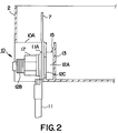
- connection box 1 including body 2 and a cover (not shown), and junction block 3.
- Junction block 3 comprises cavities 18 for connection to various electronic elements and power transmission section 4.
- Power transmission wire harness 5 carries ring terminals 5A on each end. One end is placed over transmission bolt 6 and secured by a nut. Transmission section 4 is in electrical contact with the various elements in cavities 18. Receiving end 19 of transmission harness 5 is secured to surface 7A of conductive plate 7 by insertion of bolt 8 through ring terminal 5A and hole 7B.
- Connection box 1 is provided with external power supply connecting section 10 which comprises attachment section 13 of generally rectangular shape having inner wall 14 and outer wall 13A. U-shaped cut out 13B permits entry of male screw 12B of fixing bolt 12 therein. Head 12A, with support 12C, is inserted into internal space 16 as particularly shown in Figures 3(a) and (b). Engagement projection 15 is located on the abutment surface of inner wall 14 and has retaining surface 15A which prevents head 12A from coming out of space 16. Distance a as measured on head 12A is substantially the same as distance a as measured between retaining surface 15A and inner bottom surface 14A.
- the thickness of head 12A corresponds to the distance between the inner surface of inner wall 14 and inner surface 14B of outer wall 13A.
- conductive plate 7 comprises surface 7A and surface 7C.
- Hole 7B is located in surface 7A and U-shaped cut out 7D is in an extension of surface 7C.
- Head 12A of fixing bolt 12 is inserted into attachment section 13. Engagement projection 15 retains it in place.
- Male screw 12B projects through U-shaped cut out 7D.
- Ring terminal 11A is attached to power supply harness 11 and fits over male screw 12B.
- Nut 17 is placed over male screw 12B and tightened, thereby compressing the optional washers illustrated, ring terminal 11A, and conductive plate 7 against attachment section 13, thereby securing the entire power supply section in place.
- junction block 3 receives transmission harness 5 which is connected to electronic elements 23 in cavities 18.
- the present Invention substitutes conductive plate 7 for the busbar of the prior art.
- the circuit connections could only be implemented by the use of a busbar having a complex shape which would, therefore, be unduly difficult to produce, as well as being expensive.
- the various circuits can be easily and freely wired using a simple wire harness, thus reducing material and assembly costs.
- the arrangement of supply connecting section 10 with engagement projection 15 prevents the harness from being pulled out of connection box 1. Thus, it becomes relatively easy to insert the connection box into the engine compartment of the vehicle.
Landscapes
- Engineering & Computer Science (AREA)
- Mechanical Engineering (AREA)
- Connection Or Junction Boxes (AREA)
Applications Claiming Priority (6)
| Application Number | Priority Date | Filing Date | Title |
|---|---|---|---|
| JP10784697 | 1997-04-24 | ||
| JP9107846A JPH10304536A (ja) | 1997-04-24 | 1997-04-24 | 電気接続箱 |
| JP107846/97 | 1997-04-24 | ||
| JP117088/97 | 1997-05-07 | ||
| JP9117088A JPH10313521A (ja) | 1997-05-07 | 1997-05-07 | 電気接続箱 |
| JP11708897 | 1997-05-07 |
Publications (2)
| Publication Number | Publication Date |
|---|---|
| EP0873914A2 true EP0873914A2 (fr) | 1998-10-28 |
| EP0873914A3 EP0873914A3 (fr) | 2001-10-04 |
Family
ID=26447818
Family Applications (1)
| Application Number | Title | Priority Date | Filing Date |
|---|---|---|---|
| EP98107546A Withdrawn EP0873914A3 (fr) | 1997-04-24 | 1998-04-24 | Assemblage électrique comprenant une boíte de connection contenant un bloc de jonction |
Country Status (4)
| Country | Link |
|---|---|
| US (1) | US6033269A (fr) |
| EP (1) | EP0873914A3 (fr) |
| CN (1) | CN1199259A (fr) |
| AU (1) | AU703483B2 (fr) |
Families Citing this family (9)
| Publication number | Priority date | Publication date | Assignee | Title |
|---|---|---|---|---|
| US7097509B2 (en) * | 2004-04-22 | 2006-08-29 | Cooper Technologies Company | Filtered terminal block assembly |
| US8647159B2 (en) * | 2010-03-02 | 2014-02-11 | General Electric Company | Apparatus and method for effecting electrical termination with a plurality of types of termination structures |
| CN108075419B (zh) * | 2013-04-04 | 2021-02-19 | 松下知识产权经营株式会社 | 电连接结构 |
| BR102014031592B1 (pt) * | 2014-12-17 | 2020-11-24 | Whirlpool S.A. | Sistema para montagem de dispositivo operacional de acionamento por toque em aparelhos eletrodomesticos |
| US9691580B2 (en) * | 2015-08-05 | 2017-06-27 | Cooper Technologies Company | Fuse holder and configurable bus module for power distribution system |
| US10338518B2 (en) * | 2016-07-29 | 2019-07-02 | Lexmark International, Inc. | Redundant electrical contact between a fastener and a component |
| JP6620716B2 (ja) * | 2016-10-26 | 2019-12-18 | 株式会社オートネットワーク技術研究所 | 配線モジュール |
| JP2019186110A (ja) * | 2018-04-13 | 2019-10-24 | 矢崎総業株式会社 | 端子化電線 |
| JP6820303B2 (ja) * | 2018-10-29 | 2021-01-27 | 矢崎総業株式会社 | 電気接続箱およびそのアース接続構造 |
Family Cites Families (14)
| Publication number | Priority date | Publication date | Assignee | Title |
|---|---|---|---|---|
| US1677059A (en) * | 1924-12-01 | 1928-07-10 | Paul M Tebbs | Electrical contactor |
| US2360304A (en) * | 1941-10-06 | 1944-10-10 | Crabtree & Co Ltd J A | Electric coupling |
| US2454962A (en) * | 1944-04-10 | 1948-11-30 | Gen Motors Corp | Container for electrical apparatus |
| US4210379A (en) * | 1979-03-15 | 1980-07-01 | Amp Incorporated | Modular barrier block |
| US4280748A (en) * | 1979-11-20 | 1981-07-28 | International Harvester Company | Fusible terminal |
| JPH0613558Y2 (ja) * | 1988-02-10 | 1994-04-06 | 矢崎総業株式会社 | 自動車用配線装置 |
| US4954102A (en) * | 1988-03-25 | 1990-09-04 | Yazaki Corporation | Wiring connection apparatus |
| JP2747161B2 (ja) * | 1992-04-09 | 1998-05-06 | 矢崎総業株式会社 | 電気接続箱の固定構造 |
| JP2949004B2 (ja) * | 1993-03-15 | 1999-09-13 | 住友電装株式会社 | リレーボックス |
| JP3042579B2 (ja) * | 1994-07-22 | 2000-05-15 | 矢崎総業株式会社 | 配電函のねじ止め構造 |
| US5530625A (en) * | 1994-09-07 | 1996-06-25 | Electro-Wire Products, Inc. | Electrical interface board including flat ribbon conductors positioned on edge |
| US5497036A (en) * | 1994-10-21 | 1996-03-05 | Harley-Davidson | Motorcycle terminal box assembly |
| US5674090A (en) * | 1995-03-15 | 1997-10-07 | Sumitomo Wiring Systems, Ltd. | Casing for receiving electrical connection box |
| JP3054358B2 (ja) * | 1996-03-06 | 2000-06-19 | 矢崎総業株式会社 | 電気接続箱 |
-
1998
- 1998-04-22 AU AU63524/98A patent/AU703483B2/en not_active Ceased
- 1998-04-23 US US09/064,983 patent/US6033269A/en not_active Expired - Fee Related
- 1998-04-24 CN CN98109418.XA patent/CN1199259A/zh active Pending
- 1998-04-24 EP EP98107546A patent/EP0873914A3/fr not_active Withdrawn
Non-Patent Citations (1)
| Title |
|---|
| None |
Also Published As
| Publication number | Publication date |
|---|---|
| CN1199259A (zh) | 1998-11-18 |
| AU703483B2 (en) | 1999-03-25 |
| AU6352498A (en) | 1998-10-29 |
| EP0873914A3 (fr) | 2001-10-04 |
| US6033269A (en) | 2000-03-07 |
Similar Documents
| Publication | Publication Date | Title |
|---|---|---|
| US8002569B2 (en) | Electric connection box | |
| CN101312287B (zh) | 电连接盒 | |
| CN109792140B (zh) | 电连接箱 | |
| EP0906853A2 (fr) | Boite de jonction montée sur la batterie | |
| EP0889549A1 (fr) | Une connexion entre une batterie et un boítier de connexion électrique | |
| US6042431A (en) | Joint device for an automotive wiring harness | |
| JP2002125307A (ja) | 電気接続箱 | |
| US4800358A (en) | Fuse | |
| US6033269A (en) | Electrical assembly including a connection box having a junction block therein | |
| JP2996176B2 (ja) | 自動車用電気接続箱 | |
| JP2019088126A (ja) | 電気接続箱 | |
| JP2011097711A (ja) | 電気接続箱 | |
| JP2000505943A (ja) | 電気器具 | |
| CN108242770B (zh) | 电气接线箱 | |
| US6062876A (en) | Electrical connection box for an automotive vehicle | |
| JP3290387B2 (ja) | 電気接続箱 | |
| JP2597713Y2 (ja) | 分岐接続箱 | |
| JPH0644259Y2 (ja) | 電気接続箱の取付け構造 | |
| JP7640380B2 (ja) | 電源ブロック | |
| JP2009165220A (ja) | 電気接続箱 | |
| KR100755031B1 (ko) | 배터리용 퓨즈박스의 장착구조 | |
| JP2024039990A (ja) | 車載用の電気接続箱 | |
| JP3175646B2 (ja) | 自動車用電気接続箱 | |
| JP3356117B2 (ja) | 電気接続箱 | |
| JP3916283B2 (ja) | ジャンクションボックス |
Legal Events
| Date | Code | Title | Description |
|---|---|---|---|
| PUAI | Public reference made under article 153(3) epc to a published international application that has entered the european phase |
Free format text: ORIGINAL CODE: 0009012 |
|
| 17P | Request for examination filed |
Effective date: 19980424 |
|
| AK | Designated contracting states |
Kind code of ref document: A2 Designated state(s): AT BE CH CY DE DK ES FI FR GB GR IE IT LI LU MC NL PT SE |
|
| AX | Request for extension of the european patent |
Free format text: AL;LT;LV;MK;RO;SI |
|
| PUAL | Search report despatched |
Free format text: ORIGINAL CODE: 0009013 |
|
| AK | Designated contracting states |
Kind code of ref document: A3 Designated state(s): AT BE CH CY DE DK ES FI FR GB GR IE IT LI LU MC NL PT SE |
|
| AX | Request for extension of the european patent |
Free format text: AL;LT;LV;MK;RO;SI |
|
| STAA | Information on the status of an ep patent application or granted ep patent |
Free format text: STATUS: THE APPLICATION HAS BEEN WITHDRAWN |
|
| 18W | Application withdrawn |
Withdrawal date: 20011127 |