EP0874131A2 - Gekühlter Haltering für Turbinenleitschaufeln - Google Patents
Gekühlter Haltering für Turbinenleitschaufeln Download PDFInfo
- Publication number
- EP0874131A2 EP0874131A2 EP98107560A EP98107560A EP0874131A2 EP 0874131 A2 EP0874131 A2 EP 0874131A2 EP 98107560 A EP98107560 A EP 98107560A EP 98107560 A EP98107560 A EP 98107560A EP 0874131 A2 EP0874131 A2 EP 0874131A2
- Authority
- EP
- European Patent Office
- Prior art keywords
- shroud
- space
- air
- cooling
- stationary blade
- Prior art date
- Legal status (The legal status is an assumption and is not a legal conclusion. Google has not performed a legal analysis and makes no representation as to the accuracy of the status listed.)
- Granted
Links
- 238000001816 cooling Methods 0.000 claims abstract description 91
- 239000007789 gas Substances 0.000 description 12
- 238000002347 injection Methods 0.000 description 6
- 239000007924 injection Substances 0.000 description 6
- 238000007789 sealing Methods 0.000 description 4
- 239000000567 combustion gas Substances 0.000 description 2
- 230000000694 effects Effects 0.000 description 2
- 238000007664 blowing Methods 0.000 description 1
- 238000010276 construction Methods 0.000 description 1
- 230000002708 enhancing effect Effects 0.000 description 1
- 125000006850 spacer group Chemical group 0.000 description 1
Images


Classifications
-
- F—MECHANICAL ENGINEERING; LIGHTING; HEATING; WEAPONS; BLASTING
- F01—MACHINES OR ENGINES IN GENERAL; ENGINE PLANTS IN GENERAL; STEAM ENGINES
- F01D—NON-POSITIVE DISPLACEMENT MACHINES OR ENGINES, e.g. STEAM TURBINES
- F01D9/00—Stators
- F01D9/02—Nozzles; Nozzle boxes; Stator blades; Guide conduits, e.g. individual nozzles
- F01D9/04—Nozzles; Nozzle boxes; Stator blades; Guide conduits, e.g. individual nozzles forming ring or sector
- F01D9/041—Nozzles; Nozzle boxes; Stator blades; Guide conduits, e.g. individual nozzles forming ring or sector using blades
-
- F—MECHANICAL ENGINEERING; LIGHTING; HEATING; WEAPONS; BLASTING
- F01—MACHINES OR ENGINES IN GENERAL; ENGINE PLANTS IN GENERAL; STEAM ENGINES
- F01D—NON-POSITIVE DISPLACEMENT MACHINES OR ENGINES, e.g. STEAM TURBINES
- F01D5/00—Blades; Blade-carrying members; Heating, heat-insulating, cooling or antivibration means on the blades or the members
- F01D5/12—Blades
- F01D5/14—Form or construction
- F01D5/18—Hollow blades, i.e. blades with cooling or heating channels or cavities; Heating, heat-insulating or cooling means on blades
- F01D5/187—Convection cooling
-
- F—MECHANICAL ENGINEERING; LIGHTING; HEATING; WEAPONS; BLASTING
- F05—INDEXING SCHEMES RELATING TO ENGINES OR PUMPS IN VARIOUS SUBCLASSES OF CLASSES F01-F04
- F05D—INDEXING SCHEME FOR ASPECTS RELATING TO NON-POSITIVE-DISPLACEMENT MACHINES OR ENGINES, GAS-TURBINES OR JET-PROPULSION PLANTS
- F05D2240/00—Components
- F05D2240/80—Platforms for stationary or moving blades
- F05D2240/81—Cooled platforms
-
- F—MECHANICAL ENGINEERING; LIGHTING; HEATING; WEAPONS; BLASTING
- F05—INDEXING SCHEMES RELATING TO ENGINES OR PUMPS IN VARIOUS SUBCLASSES OF CLASSES F01-F04
- F05D—INDEXING SCHEME FOR ASPECTS RELATING TO NON-POSITIVE-DISPLACEMENT MACHINES OR ENGINES, GAS-TURBINES OR JET-PROPULSION PLANTS
- F05D2260/00—Function
- F05D2260/20—Heat transfer, e.g. cooling
- F05D2260/221—Improvement of heat transfer
- F05D2260/2212—Improvement of heat transfer by creating turbulence
Definitions
- the present invention relates to a cooled shroud having a cooling structure in a gas turbine stationary blade.
- Fig. 5 is a perspective view showing one typical example of a cooling system in a prior art gas turbine stationary blade.
- numeral 30 designates a stationary blade
- numeral 31 designates an outer shroud thereof
- numeral 32 designates an inner shroud.
- Numeral 33, 34 and 35 respectively, designates an insert, arranged in the order of place from a leading edge side toward a trailing edge side, inserted in the direction from the outer shroud 31 toward the inner shroud 32
- numeral 33a, 34a and 35a respectively, designates an air injection hole provided to the respective insert
- numeral 36 designates a trailing edge fin.
- Numeral 37 generally designates an air injection hole provided in a blade surface for blowing air, wherein numerals 37a and 37c are shown in the figure and numeral 37b is not shown.
- cooling air is introduced through the outer shroud 31 and the inner shroud 32, respectively, into the inserts 33, 34 and 35 and is blown from the air injection holes 33a, 34a and 35a toward a blade inner surface to perform an impingement cooling of the blade inner surface and is then blown from the air injection holes 37a, 37b and 37c, provided in the blade surface, to perform a shower head cooling, a film cooling and a pin fin cooling of the blade.
- the cooling of the shroud it is done, as shown in the figure as one example, such that the cooling air which flows in is injected to impinge rectangularly on an impingement plate 39 which is provided in the inner shroud 32 in parallel thereto so that the air passes through a multiplicity of holes to be diffused to cool an entire surface of the inner shroud 32 and is then flown out of a rear end of the shroud.
- Fig. 6 shows another example of a stationary blade cooling system.
- numeral 40 designates a stationary blade
- numeral 41 designates an outer shroud thereof
- numeral 42 designates an inner shroud
- Numeral 43A, 43B, 43C, 43D and 43E respectively, designates an air passage
- numeral 45 designates an air injection hole of a trailing edge
- numeral 46 designates a turbulator provided to an inner wall of the air passage 43A to 43D, respectively, for making the air flow there turbulent for enhancement of a heat transfer.
- a cooling air 47 flows in from the outer shroud 41 into the air passage 43A to flow to a base portion, to enter therefrom the next air passage 43B, to flow to a tip portion, to enter therefrom the next air passage 43C and then likewise to flow in the air passages 43D and 43E, sequentially, to cool the blade, and is blown out of the air passage 43E through the air injection hole 44 of the trailing edge and a remaining air flows down out of the inner shroud 42.
- the cooling of the shroud is done, as the example shown in Fig. 5, such that the cooling air is flown to impinge on the impingement plate provided in the shroud and is flown in the shroud through the multiplicity of holes to cool the shroud and then is discharged through an air passage in the rear end of the shroud, however, there is applied no cooling of the shroud in the stationary blade of a turbine rear stage side, as shown in Fig. 6.
- a second object of the present invention to provide a cooled shroud having a structure to perform an integrated cooling of the shroud including a plurality of stationary blades by arranging the plurality of stationary blades in a segment of one inner shroud.
- the present invention provides following means of (1) and (2) below:
- the cooling air passes through the stationary blade leading edge side air passage to enter the first space of the inner shroud.
- a portion of the cooling air in the first space passes through the inner shroud side air passage to enter the second space while cooling the shroud leading edge side.
- the cooling air which has entered the first and second spaces is blown out of the trailing edge while cooling the surface of the shroud on the ventral side and dorsal side, respectively, of the stationary blade, so that cooling of the trailing edge portion also is effected.
- the cooling air is so introduced through the independent air passage in the stationary blade leading edge portion to flow in the first and second spaces and the shroud side air passage, thus the surroundings, leading edge portion and trailing edge portion of the inner shroud are cooled uniformly.
- a plurality of stationary blades are fixed to one inner shroud and the cooling air passes through the air passage of each of the plurality of stationary blades to enter the respective first space and a portion of the cooling air passes through the shroud side air passage to enter the second space while cooling the shroud leading edge side, same as in (1) above.
- the shroud surface on the dorsal side of the endmost stationary blade is cooled, and in the first space, the shroud surfaces of the remaining stationary blades are cooled.
- the cooling air is discharged to the trailing edge and the entire area of the shrouds of the plurality of stationary blades can be cooled uniformly, same as in (1) above.
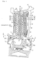
- Fig. 1 is a cross sectional view of an interior of a cooled shroud of a gas turbine stationary blade of a first and second embodiments according to the present invention.
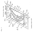
- Fig. 2 is a cross sectional view taken on line A-A of Fig. 1 and shows the cooled shroud of the first embodiment of the present invention.
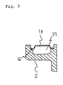
- Fig. 3 is a cross sectional view taken on line B-B of Fig. 2.
- Fig. 4 is a cross sectional view of an interior of the cooled shroud of a gas turbine stationary blade of the second embodiment of the present invention.
- Fig. 5 is a perspective view showing a cooling structure of a prior art gas turbine stationary blade.
- Fig. 6 is a cross sectional view showing an interior of another cooling structure of a prior art gas turbine stationary blade.
- Fig. 1 is a cross sectional view of an interior of a gas turbine stationary blade to which a cooled shroud of a first embodiment according to the present invention is applied and
- Fig. 2 is a cross sectional view taken on line A-A of Fig. 1 and shows an interior of an inner shroud thereof.
- numeral 1 designates a stationary blade
- numeral 2 designates an inner shroud thereof
- numeral 10 designates an outer shroud thereof
- Numeral 3A, 3B, 3C, 3D, 3E and 3F respectively, designates an air passage in the blade, wherein the air passage 3A is an independent passage on a leading edge side, and 3B which communicates with 3C on a base portion side, 3C which communicates with 3D on a tip portion side, 3D which communicates with 3E on the base portion side and 3E which communicates with 3F on the tip portion side form a serpentine cooling passage.
- Numeral 4 designates a turbulator provided to an inner wall of the air passage 3A to 3F, respectively, for making a flow of air turbulent for enhancement of a heat transfer.
- a turbulator on the leading edge side which is rectangular to the flow of the cooling air and a turbulator on a rear side thereof which is inclined to the flow of the cooling air.
- Numeral 5 designates a tube for receiving a sealing air 26 to lead it into a cavity 6 of a lower portion thereof to make a high pressure therein.
- Numeral 7 and 8, respectively, designates also a cavity and the respective cavity 6, 7 and 8 stores a high pressure low temperature cooling air, the high pressure air of which prevents an outside high temperature combustion gas from entering therein.
- Numeral 9a designates a cover to which a front honeycomb seal is provided and numeral 9b designates a cover to which a rear honeycomb seal is provided.
- Numeral 11 designates a tunnel formed by a rib 20a in the inner shroud 2
- numeral 12 designates a leading edge side passage of the inner shroud 2
- numeral 13 designates a cover of a lower portion of the inner shroud 2.
- one piece of the stationary blade is fixed to the inner shroud 2 and therein provided are the air passages 3A, 3B, 3C, 3D, 3E and 3F and the tube 5 for the sealing air.
- the tunnel 11 is formed by the rib 20a of the leading edge side at two places, one on each side of the shroud, so as to communicate with a space 21 (corresponding to a second space of the present invention) and a space 22 (corresponding to a first space of the present invention).
- the leading edge side passage 12 communicates with the tunnel 11 at each end thereof.
- the cover 13 covers surroundings of a dorsal side of ⁇ the stationary blade, abutting at its edge on a bank 16 of the inner shroud 2, as shown in Fig. 3 which is a cross sectional view taken on line B-B of Fig. 2, to form the space 21 (the second space.
- Numeral 14 designates also a cover, which abuts on a bank 15 to cover surroundings of a ventral side of the stationary blade and to form the space 22 (the first space).
- the space 22 communicates with the base portion side of the air passage 3A of the leading edge portion of the stationary blade and the cooling air is introduced there through the air passage 3A from the outer shroud 10.
- Numeral 18 designates a tunnel formed by a rib 20b of a trailing edge side, which tunnel is provided at two places so as to communicate with an air reservoir 19-1 and 19-2, respectively, and the air is blown out of holes of the trailing edge side from these air reservoirs.
- the sealing air 26 flows into the tube 5 through the outer shroud 10 to enter the cavity 6 of the lower portion of the inner shroud and to further flow therefrom into the cavities 7 and 8 to make a high pressure therein, so that a high temperature gas from a combustion gas passage is prevented from coming therein.
- the cooling of the blade is done such that the cooling air 25 enters the air passage 3B through the outer shroud 10 to flow from the base portion of the air passage 3B into the air passage 3C, to flow from the tip portion of the air passage 3C into the air passage 3D, and then from the base portion of 3D into 3E and from the tip portion of 3E into 3F, to cool the blade and then is blown out of holes of the trailing edge side of the air passage 3F.
- the cooling air 25 enters the air passage 3A of the leading edge side.
- the air passage 3A being provided independent of the other air passages, the air which has cooled the leading edge flows in its entirety into the inner shroud 2.
- the rectangular turbulator and the inclined turbulator in the air passage 3A give especially a large effect of cooling of the leading edge side.
- the cooling air flowing in the air passage 3A flows in the inner shroud 2 as shown in Fig. 2.
- the air passage 3A communicates with the space 22. That is, the air passage 3A of the stationary blade communicates with the space 22 and the cooling air flows first into the space 22.
- the cooling air which has flown into the space 22 flows toward the trailing edge side while cooling a surface of the shroud central portion and further flows through the tunnel 18 to enter the air reservoir 19-2 and is then blown out of holes of the trailing edge side while cooling an entire area of the trailing edge side.
- a portion of the cooling air in the space 22 passes through the tunnel 11 of-the right side end in Fig. 2, through the leading edge side passage 12 while cooling the leading edge side and through the tunnel 11 of the left side end in Fig. 2 and enters the space 21.
- the cooling air in the space 21 flows through the tunnel 18 of the left side end while cooling a surface of the left side end portion of the inner shroud 2 to enter the air reservoir 19-1 and is then blown out of holes of the trailing edge side while cooling the trailing edge side of the left side end.
- Fig. 4 is a cross sectional view of an interior of a cooled shroud of a second embodiment according to the present invention.
- a different point from the first embodiment is that the cooled shroud is fixed with three stationary blades integrally. That is, three stationary blades are fixed to the inner shroud 2 integrally and, as shown by numerals representatively for the stationary blade of the left side end in Fig. 4, there are provided air passages 3A, 3B, 3C, 3D, 3E and 3F and a tube 5 for a sealing air for each of the stationary blades.
- Numeral 11 designates a tunnel formed by a rib 20a of a leading edge side, which tunnel is provided at two places of each side of the shroud so as to communicate with space 21 and 21b, respectively.
- Numeral 12 designates a leading edge side passage, which is same as mentioned above and communicates at its each end with the tunnel 11.
- Numeral 13 designates a cover for covering surroundings of a dorsal side of the stationary blade of the left side end, which cover abuts at its edge on a bank 16 of the inner shroud 2 to form the space 21.
- Numeral 14 designates also a cover, which abuts on a bank 15 to cover entire surroundings of the remaining stationary blades of the middle and the right side end and forms spaces 22a, 22b and 22c.
- the space 22a, 22b and 22c communicates with a base portion side of the air passage 3A of the leading edge portion of each of the three stationary blades and a cooling air is introduced there through the air passage 3A from an outer shroud 10.
- a spacer 17a, 17b In the space 22a and 22b, respectively, there is provided a spacer 17a, 17b.
- Numeral 18 designates a tunnel formed by a rib 20b of the trailing edge side, which tunnel is provided at four places to communicate with air reservoir 19-1, 19-2, 19-3 and 19-4, respectively, and the cooling air therefrom is blown out of holes of the trailing edge side.
- cooling of the blade being done in the same way as described for the first embodiment, repeated description thereof is omitted and cooling of the inner shroud will be described.
- a cooling air 25 enters the air passage 3A of the leading hedge side.
- the air passage 3A being provided independent of the other air passages, the air which has cooled the leading edge flows in its entirety into the inner shroud 2.
- Three stationary blades are fixed to the inner shroud 2 integrally, as shown in Fig. 4, and the cooling air which has flown from the air passage 3A of each of the stationary blades flows into the inner shroud 2.
- Each air passage 3A communicates with the space 22a, 22b and 22c such that the air passage 3A of the stationary blade of the left side end in the figure communicates with the space 22a, the air passage 3A of the middle communicates with the spaces 22a and 22b and the air passage 3A of the stationary blade of the right side end communicates with the spaces 22b and 22c, and the cooling air flows first into the spaces 22a, 22b and 22c.
- the cooling air which has flown in the spaces 22a, 22b and 22c flows further to the trailing edge side while cooling a surface of a central portion of the shroud 2 to enter the air reservoirs 19-2, 19-3 and 19-4 through the tunnels 11 of three places and is then blown out of holes of the trailing edge side while cooling an entire area of the trailing edge side.
- a portion of the cooling air in the space 22b passes through the tunnel 11 of the right side end, through the leading edge side passage 12 while cooling the leading edge side and through the tunnel 11 of the left side end to enter the space 21.
- the cooling air in the space 21 flows through the tunnel 18 of the left side end while cooling a surface of the left side end portion of the inner shroud 2 to enter the air reservoir 19-1 and is then blown out of holes of the trailing edge side while cooling the trailing edge side of the left side end.
- the present invention is not limited to this example using a segment of three stationary blades but may be constructed by use of a segment of two, or four or more, stationary blades.
- the inner shroud 2 is constructed with one or three stationary blades fixed thereto, and the cooling air is supplied into the independent air passage 3A of the leading edge side of each stationary blade to flow into the space 22 or 22a, 22b and 22c covered and sealed by the cover 14 to cool the surface of the shroud and then passes through the tunnel 18 and the air reservoirs 19-2, 19-3 and 19-4 to be blown out of the trailing edge.
- the cooling air flows through the tunnel 11 and the leading edge side passage 12 from the space 22 or 22b to cool the leading edge side and enters the space 21 to cool the surface of the left side end of the shroud and, passing through the tunnel 18 and the air reservoir 19-1, is blown out of the leading edge side while cooling the trailing edge portion of the left side.
- the entire area of the leading edge, middle portion, trailing edge and both end portions of the shroud can be cooled by use of a cooling air and further, three stationary blades being fixed to the inner shroud integrally in one unit, each portion to be cooled of the blades can be cooled integrally, hence the cooling passages can be simplified and the cooling performance of the shroud can be enhanced.
Landscapes
- Engineering & Computer Science (AREA)
- Mechanical Engineering (AREA)
- General Engineering & Computer Science (AREA)
- Turbine Rotor Nozzle Sealing (AREA)
Applications Claiming Priority (4)
| Application Number | Priority Date | Filing Date | Title |
|---|---|---|---|
| JP107444/97 | 1997-04-24 | ||
| JP10744497 | 1997-04-24 | ||
| JP10744497A JP3495554B2 (ja) | 1997-04-24 | 1997-04-24 | ガスタービン静翼の冷却シュラウド |
| US09/064,987 US5997245A (en) | 1997-04-24 | 1998-04-23 | Cooled shroud of gas turbine stationary blade |
Publications (3)
| Publication Number | Publication Date |
|---|---|
| EP0874131A2 true EP0874131A2 (de) | 1998-10-28 |
| EP0874131A3 EP0874131A3 (de) | 2000-01-05 |
| EP0874131B1 EP0874131B1 (de) | 2003-03-19 |
Family
ID=26447478
Family Applications (1)
| Application Number | Title | Priority Date | Filing Date |
|---|---|---|---|
| EP98107560A Expired - Lifetime EP0874131B1 (de) | 1997-04-24 | 1998-04-24 | Gekühlter Haltering für Turbinenleitschaufeln |
Country Status (3)
| Country | Link |
|---|---|
| US (1) | US5997245A (de) |
| EP (1) | EP0874131B1 (de) |
| JP (1) | JP3495554B2 (de) |
Cited By (10)
| Publication number | Priority date | Publication date | Assignee | Title |
|---|---|---|---|---|
| EP1083299A3 (de) * | 1999-09-07 | 2004-03-17 | General Electric Company | Innnengekühlte Deckringsegmente für Turbomaschinenschaufeln |
| EP1347152A3 (de) * | 2002-03-22 | 2005-03-16 | General Electric Company | Gekühlter Leitapparat |
| EP1384855A3 (de) * | 2002-07-25 | 2005-08-17 | Mitsubishi Heavy Industries, Ltd. | Kühlstruktur einer Turbinenleitschaufel und Gasturbine |
| EP1895105A1 (de) * | 2006-08-30 | 2008-03-05 | Siemens Aktiengesellschaft | Verfahren zum Kühlen von Turbinenschaufeln eines Schaufelkranzes sowie Turbinenschaufelsegment für einen Turbinenschaufelkranz mit mindestens zwei aerodynamisch profilierten Schaufelblättern |
| GB2455644A (en) * | 2007-12-17 | 2009-06-24 | Gen Electric | Turbine nozzle cooling |
| EP2397653A1 (de) * | 2010-06-17 | 2011-12-21 | Siemens Aktiengesellschaft | Plattformsegment zur Stützung einer Gasturbinenleitschaufel und Kühlungsverfahren |
| EP3051065A1 (de) * | 2015-01-20 | 2016-08-03 | United Technologies Corporation | Schaufelplattform mit kern mit auslassschlitzen |
| CN106460534A (zh) * | 2014-06-30 | 2017-02-22 | 三菱日立电力系统株式会社 | 涡轮静叶、涡轮、以及涡轮静叶的改造方法 |
| CN106536867A (zh) * | 2014-08-04 | 2017-03-22 | 三菱日立电力系统株式会社 | 静叶、燃气轮机、分割环、静叶的改造方法以及分割环的改造方法 |
| US11156102B2 (en) | 2018-03-19 | 2021-10-26 | General Electric Company | Blade having a tip cooling cavity and method of making same |
Families Citing this family (38)
| Publication number | Priority date | Publication date | Assignee | Title |
|---|---|---|---|---|
| JP3316415B2 (ja) * | 1997-05-01 | 2002-08-19 | 三菱重工業株式会社 | ガスタービン冷却静翼 |
| CA2263508C (en) * | 1997-06-19 | 2003-08-19 | Mitsubishi Heavy Industries, Ltd. | Sealing device for gas turbine stator blades |
| ITMI991208A1 (it) * | 1999-05-31 | 2000-12-01 | Nuovo Pignone Spa | Dispositivo per il posizionamento di ugelli di uno stadio statorico eper il raffreddamento di dischi rotorici in turbine a gas |
| US6227798B1 (en) * | 1999-11-30 | 2001-05-08 | General Electric Company | Turbine nozzle segment band cooling |
| JP3782637B2 (ja) * | 2000-03-08 | 2006-06-07 | 三菱重工業株式会社 | ガスタービン冷却静翼 |
| US6439837B1 (en) * | 2000-06-27 | 2002-08-27 | General Electric Company | Nozzle braze backside cooling |
| US6884023B2 (en) * | 2002-09-27 | 2005-04-26 | United Technologies Corporation | Integral swirl knife edge injection assembly |
| US7007488B2 (en) * | 2004-07-06 | 2006-03-07 | General Electric Company | Modulated flow turbine nozzle |
| US7121793B2 (en) * | 2004-09-09 | 2006-10-17 | General Electric Company | Undercut flange turbine nozzle |
| GB2427657B (en) * | 2005-06-28 | 2011-01-19 | Siemens Ind Turbomachinery Ltd | A gas turbine engine |
| US7377743B2 (en) * | 2005-12-19 | 2008-05-27 | General Electric Company | Countercooled turbine nozzle |
| US7625172B2 (en) * | 2006-04-26 | 2009-12-01 | United Technologies Corporation | Vane platform cooling |
| US7488157B2 (en) * | 2006-07-27 | 2009-02-10 | Siemens Energy, Inc. | Turbine vane with removable platform inserts |
| US7581924B2 (en) * | 2006-07-27 | 2009-09-01 | Siemens Energy, Inc. | Turbine vanes with airfoil-proximate cooling seam |
| US7836703B2 (en) * | 2007-06-20 | 2010-11-23 | General Electric Company | Reciprocal cooled turbine nozzle |
| US8104292B2 (en) * | 2007-12-17 | 2012-01-31 | General Electric Company | Duplex turbine shroud |
| US8205458B2 (en) | 2007-12-31 | 2012-06-26 | General Electric Company | Duplex turbine nozzle |
| US8096758B2 (en) * | 2008-09-03 | 2012-01-17 | Siemens Energy, Inc. | Circumferential shroud inserts for a gas turbine vane platform |
| US8096772B2 (en) * | 2009-03-20 | 2012-01-17 | Siemens Energy, Inc. | Turbine vane for a gas turbine engine having serpentine cooling channels within the inner endwall |
| US8490408B2 (en) * | 2009-07-24 | 2013-07-23 | Pratt & Whitney Canada Copr. | Continuous slot in shroud |
| GB201016423D0 (en) * | 2010-09-30 | 2010-11-17 | Rolls Royce Plc | Cooled rotor blade |
| EP2700787B1 (de) | 2011-04-22 | 2018-04-04 | Mitsubishi Hitachi Power Systems, Ltd. | Schaufelglied und drehmaschine |
| US9394915B2 (en) | 2012-06-04 | 2016-07-19 | United Technologies Corporation | Seal land for static structure of a gas turbine engine |
| US9175565B2 (en) | 2012-08-03 | 2015-11-03 | General Electric Company | Systems and apparatus relating to seals for turbine engines |
| US9631517B2 (en) | 2012-12-29 | 2017-04-25 | United Technologies Corporation | Multi-piece fairing for monolithic turbine exhaust case |
| US10240470B2 (en) * | 2013-08-30 | 2019-03-26 | United Technologies Corporation | Baffle for gas turbine engine vane |
| US9562439B2 (en) * | 2013-12-27 | 2017-02-07 | General Electric Company | Turbine nozzle and method for cooling a turbine nozzle of a gas turbine engine |
| US9771816B2 (en) | 2014-05-07 | 2017-09-26 | General Electric Company | Blade cooling circuit feed duct, exhaust duct, and related cooling structure |
| US9638045B2 (en) * | 2014-05-28 | 2017-05-02 | General Electric Company | Cooling structure for stationary blade |
| US9909436B2 (en) | 2015-07-16 | 2018-03-06 | General Electric Company | Cooling structure for stationary blade |
| US10900378B2 (en) | 2017-06-16 | 2021-01-26 | Honeywell International Inc. | Turbine tip shroud assembly with plural shroud segments having internal cooling passages |
| US10677084B2 (en) | 2017-06-16 | 2020-06-09 | Honeywell International Inc. | Turbine tip shroud assembly with plural shroud segments having inter-segment seal arrangement |
| US10989067B2 (en) * | 2018-07-13 | 2021-04-27 | Honeywell International Inc. | Turbine vane with dust tolerant cooling system |
| US11230929B2 (en) | 2019-11-05 | 2022-01-25 | Honeywell International Inc. | Turbine component with dust tolerant cooling system |
| US12173619B2 (en) | 2022-05-02 | 2024-12-24 | Siemens Energy Global GmbH & Co. KG | Turbine component having platform cooling circuit |
| JP7847031B2 (ja) * | 2022-05-06 | 2026-04-16 | 三菱重工業株式会社 | タービン翼及びガスタービン |
| JP7710111B2 (ja) * | 2022-07-19 | 2025-07-17 | 三菱重工業株式会社 | ガスタービン静翼及びガスタービン |
| GB2633337A (en) * | 2023-09-06 | 2025-03-12 | Siemens Energy Global Gmbh & Co Kg | Turbine component for gas turbine engine |
Family Cites Families (8)
| Publication number | Priority date | Publication date | Assignee | Title |
|---|---|---|---|---|
| FR2723144B1 (fr) | 1984-11-29 | 1996-12-13 | Snecma | Distributeur de turbine |
| JP3015531B2 (ja) * | 1991-09-06 | 2000-03-06 | 株式会社東芝 | ガスタービン |
| FR2692318B1 (fr) * | 1992-06-11 | 1994-08-19 | Snecma | Aubage fixe de distribution des gaz chauds d'une turbo-machine. |
| US5344283A (en) * | 1993-01-21 | 1994-09-06 | United Technologies Corporation | Turbine vane having dedicated inner platform cooling |
| US5413458A (en) * | 1994-03-29 | 1995-05-09 | United Technologies Corporation | Turbine vane with a platform cavity having a double feed for cooling fluid |
| US5634766A (en) * | 1994-08-23 | 1997-06-03 | General Electric Co. | Turbine stator vane segments having combined air and steam cooling circuits |
| ES2144147T3 (es) | 1994-11-10 | 2000-06-01 | Siemens Westinghouse Power | Alabe de turbina de gas con mortaja interna refrigerada. |
| US5848876A (en) * | 1997-02-11 | 1998-12-15 | Mitsubishi Heavy Industries, Ltd. | Cooling system for cooling platform of gas turbine moving blade |
-
1997
- 1997-04-24 JP JP10744497A patent/JP3495554B2/ja not_active Expired - Lifetime
-
1998
- 1998-04-23 US US09/064,987 patent/US5997245A/en not_active Expired - Lifetime
- 1998-04-24 EP EP98107560A patent/EP0874131B1/de not_active Expired - Lifetime
Cited By (23)
| Publication number | Priority date | Publication date | Assignee | Title |
|---|---|---|---|---|
| EP1083299A3 (de) * | 1999-09-07 | 2004-03-17 | General Electric Company | Innnengekühlte Deckringsegmente für Turbomaschinenschaufeln |
| EP1347152A3 (de) * | 2002-03-22 | 2005-03-16 | General Electric Company | Gekühlter Leitapparat |
| EP1384855A3 (de) * | 2002-07-25 | 2005-08-17 | Mitsubishi Heavy Industries, Ltd. | Kühlstruktur einer Turbinenleitschaufel und Gasturbine |
| EP1895105A1 (de) * | 2006-08-30 | 2008-03-05 | Siemens Aktiengesellschaft | Verfahren zum Kühlen von Turbinenschaufeln eines Schaufelkranzes sowie Turbinenschaufelsegment für einen Turbinenschaufelkranz mit mindestens zwei aerodynamisch profilierten Schaufelblättern |
| WO2008025583A1 (de) * | 2006-08-30 | 2008-03-06 | Siemens Aktiengesellschaft | Verfahren zum kühlen von turbinenschaufeln eines schaufelkranzes sowie turbinenschaufelsegment für einen turbinenschaufelkranz mit mindestens zwei aerodynamisch profilierten schaufelblättern |
| GB2455644B (en) * | 2007-12-17 | 2012-04-18 | Gen Electric | Divergent turbine nozzle |
| GB2455644A (en) * | 2007-12-17 | 2009-06-24 | Gen Electric | Turbine nozzle cooling |
| US8281604B2 (en) | 2007-12-17 | 2012-10-09 | General Electric Company | Divergent turbine nozzle |
| CN102947549A (zh) * | 2010-06-17 | 2013-02-27 | 西门子公司 | 支撑燃气轮机的喷嘴引导叶瓣的平台节段及其冷却方法 |
| WO2011157549A1 (en) * | 2010-06-17 | 2011-12-22 | Siemens Aktiengesellschaft | Platform segment for supporting a nozzle guide vane for a gas turbine and method of cooling thereof |
| EP2397653A1 (de) * | 2010-06-17 | 2011-12-21 | Siemens Aktiengesellschaft | Plattformsegment zur Stützung einer Gasturbinenleitschaufel und Kühlungsverfahren |
| US8668440B2 (en) | 2010-06-17 | 2014-03-11 | Siemens Aktiengesellschaft | Platform segment for supporting a nozzle guide vane for a gas turbine and nozzle guide vane arrangement for a gas turbine |
| US10544685B2 (en) | 2014-06-30 | 2020-01-28 | Mitsubishi Hitachi Power Systems, Ltd. | Turbine vane, turbine, and turbine vane modification method |
| CN106460534A (zh) * | 2014-06-30 | 2017-02-22 | 三菱日立电力系统株式会社 | 涡轮静叶、涡轮、以及涡轮静叶的改造方法 |
| CN106460534B (zh) * | 2014-06-30 | 2018-05-18 | 三菱日立电力系统株式会社 | 涡轮静叶、涡轮、以及涡轮静叶的改造方法 |
| DE112015003047B4 (de) | 2014-06-30 | 2021-08-26 | Mitsubishi Power, Ltd. | Turbinenleitschaufel, turbine und verfahren zum modifizieren einer turbinenleitschaufel |
| CN106536867A (zh) * | 2014-08-04 | 2017-03-22 | 三菱日立电力系统株式会社 | 静叶、燃气轮机、分割环、静叶的改造方法以及分割环的改造方法 |
| CN106536867B (zh) * | 2014-08-04 | 2018-05-22 | 三菱日立电力系统株式会社 | 静叶、燃气轮机、分割环、静叶的改造方法以及分割环的改造方法 |
| US10724404B2 (en) | 2014-08-04 | 2020-07-28 | Mitsubishi Hitachi Power Systems, Ltd. | Vane, gas turbine, ring segment, remodeling method for vane, and remodeling method for ring segment |
| US10041357B2 (en) | 2015-01-20 | 2018-08-07 | United Technologies Corporation | Cored airfoil platform with outlet slots |
| EP3051065A1 (de) * | 2015-01-20 | 2016-08-03 | United Technologies Corporation | Schaufelplattform mit kern mit auslassschlitzen |
| US10808549B2 (en) | 2015-01-20 | 2020-10-20 | Raytheon Technologies Corporation | Cored airfoil platform with outlet slots |
| US11156102B2 (en) | 2018-03-19 | 2021-10-26 | General Electric Company | Blade having a tip cooling cavity and method of making same |
Also Published As
| Publication number | Publication date |
|---|---|
| JPH10299409A (ja) | 1998-11-10 |
| EP0874131B1 (de) | 2003-03-19 |
| EP0874131A3 (de) | 2000-01-05 |
| JP3495554B2 (ja) | 2004-02-09 |
| US5997245A (en) | 1999-12-07 |
Similar Documents
| Publication | Publication Date | Title |
|---|---|---|
| US5997245A (en) | Cooled shroud of gas turbine stationary blade | |
| US4010531A (en) | Tip cap apparatus and method of installation | |
| KR100569765B1 (ko) | 터빈블레이드 | |
| CA1040538A (en) | Tip cap apparatus and method of installation | |
| US6190130B1 (en) | Gas turbine moving blade platform | |
| JP2668207B2 (ja) | ガスタービンエンジンのタービンのエーロフオイルセクシヨン | |
| US4946346A (en) | Gas turbine vane | |
| EP1116861B1 (de) | Kreislauf zum Kühlen von Gasturbinenschaufeln | |
| US5609466A (en) | Gas turbine vane with a cooled inner shroud | |
| EP0945595A2 (de) | Gekühlte Gasturbinenschaufel | |
| EP1267038A2 (de) | Gekühltes Schaufelblatt | |
| US6468031B1 (en) | Nozzle cavity impingement/area reduction insert | |
| US6416275B1 (en) | Recessed impingement insert metering plate for gas turbine nozzles | |
| JP4393667B2 (ja) | 蒸気・空気冷却タービンノズル段用の冷却回路 | |
| EP0937863A2 (de) | Plattform für eine Gasturbinenlaufschaufel | |
| US6146098A (en) | Tip shroud for cooled blade of gas turbine | |
| EP1985804A1 (de) | Kühlstruktur | |
| CN109477393B (zh) | 具有用于中部本体温度控制的独立冷却回路的涡轮翼型件 | |
| EP0911488B1 (de) | Gekühlte Statorschaufel für Gasturbinen | |
| EP1094200A1 (de) | Gekühlte Gasturbinenrotorschaufel | |
| CA2234922C (en) | Cooled shroud of gas turbine stationary blade | |
| JPH06229204A (ja) | ガスタービン空冷動翼の翼先端部の冷却構造 | |
| KR100528628B1 (ko) | 가스터빈베인의트레일링에지를냉각시키기위한냉각채널의구조 | |
| CA2258206C (en) | Configuration of cooling channels for cooling the trailing edge of gas turbine vanes | |
| KR20250056276A (ko) | 가스 터빈의 정익의 냉각 방법 및 냉각 구조 |
Legal Events
| Date | Code | Title | Description |
|---|---|---|---|
| PUAI | Public reference made under article 153(3) epc to a published international application that has entered the european phase |
Free format text: ORIGINAL CODE: 0009012 |
|
| 17P | Request for examination filed |
Effective date: 19980520 |
|
| AK | Designated contracting states |
Kind code of ref document: A2 Designated state(s): CH DE FR GB IT LI |
|
| AX | Request for extension of the european patent |
Free format text: AL;LT;LV;MK;RO;SI |
|
| PUAL | Search report despatched |
Free format text: ORIGINAL CODE: 0009013 |
|
| AK | Designated contracting states |
Kind code of ref document: A3 Designated state(s): AT BE CH CY DE DK ES FI FR GB GR IE IT LI LU MC NL PT SE |
|
| AX | Request for extension of the european patent |
Free format text: AL;LT;LV;MK;RO;SI |
|
| AKX | Designation fees paid |
Free format text: CH DE FR GB IT LI |
|
| 17Q | First examination report despatched |
Effective date: 20020321 |
|
| GRAH | Despatch of communication of intention to grant a patent |
Free format text: ORIGINAL CODE: EPIDOS IGRA |
|
| GRAH | Despatch of communication of intention to grant a patent |
Free format text: ORIGINAL CODE: EPIDOS IGRA |
|
| GRAA | (expected) grant |
Free format text: ORIGINAL CODE: 0009210 |
|
| AK | Designated contracting states |
Designated state(s): CH DE FR GB IT LI |
|
| REG | Reference to a national code |
Ref country code: GB Ref legal event code: FG4D |
|
| REG | Reference to a national code |
Ref country code: CH Ref legal event code: EP |
|
| REF | Corresponds to: |
Ref document number: 69812209 Country of ref document: DE Date of ref document: 20030424 Kind code of ref document: P |
|
| REG | Reference to a national code |
Ref country code: CH Ref legal event code: NV Representative=s name: DR. R.C. SALGO EUROPEAN PATENT ATTORNEY |
|
| ET | Fr: translation filed | ||
| PLBE | No opposition filed within time limit |
Free format text: ORIGINAL CODE: 0009261 |
|
| STAA | Information on the status of an ep patent application or granted ep patent |
Free format text: STATUS: NO OPPOSITION FILED WITHIN TIME LIMIT |
|
| 26N | No opposition filed |
Effective date: 20031222 |
|
| REG | Reference to a national code |
Ref country code: CH Ref legal event code: PFA Owner name: MITSUBISHI HEAVY INDUSTRIES, LTD. Free format text: MITSUBISHI HEAVY INDUSTRIES, LTD.#5-1, MARUNOUCHI 2-CHOME, CHIYODA-KU,#TOKYO 100-0005 (JP) -TRANSFER TO- MITSUBISHI HEAVY INDUSTRIES, LTD.#5-1, MARUNOUCHI 2-CHOME, CHIYODA-KU,#TOKYO 100-0005 (JP) |
|
| REG | Reference to a national code |
Ref country code: FR Ref legal event code: PLFP Year of fee payment: 18 |
|
| REG | Reference to a national code |
Ref country code: DE Ref legal event code: R082 Ref document number: 69812209 Country of ref document: DE Representative=s name: PATENTANWAELTE HENKEL, BREUER & PARTNER, DE Ref country code: DE Ref legal event code: R081 Ref document number: 69812209 Country of ref document: DE Owner name: MITSUBISHI HITACHI POWER SYSTEMS, LTD., YOKOHA, JP Free format text: FORMER OWNER: MITSUBISHI HEAVY INDUSTRIES, LTD., TOKYO, JP |
|
| REG | Reference to a national code |
Ref country code: FR Ref legal event code: CA Effective date: 20151119 |
|
| REG | Reference to a national code |
Ref country code: GB Ref legal event code: 732E Free format text: REGISTERED BETWEEN 20151203 AND 20151209 |
|
| REG | Reference to a national code |
Ref country code: FR Ref legal event code: TP Owner name: MITSUBISHI HITACHI POWER SYSTEMS, LTD., JP Effective date: 20151222 |
|
| REG | Reference to a national code |
Ref country code: FR Ref legal event code: PLFP Year of fee payment: 19 |
|
| REG | Reference to a national code |
Ref country code: FR Ref legal event code: PLFP Year of fee payment: 20 |
|
| PGFP | Annual fee paid to national office [announced via postgrant information from national office to epo] |
Ref country code: FR Payment date: 20170313 Year of fee payment: 20 |
|
| PGFP | Annual fee paid to national office [announced via postgrant information from national office to epo] |
Ref country code: CH Payment date: 20170412 Year of fee payment: 20 Ref country code: GB Payment date: 20170419 Year of fee payment: 20 Ref country code: DE Payment date: 20170420 Year of fee payment: 20 |
|
| PGFP | Annual fee paid to national office [announced via postgrant information from national office to epo] |
Ref country code: IT Payment date: 20170420 Year of fee payment: 20 |
|
| REG | Reference to a national code |
Ref country code: CH Ref legal event code: PCOW Free format text: NEW ADDRESS: 16-5, KONAN 2-CHOME MINATO-KU, TOKYO 108-8215 (JP) |
|
| REG | Reference to a national code |
Ref country code: CH Ref legal event code: PUE Owner name: MITSUBISHI HITACHI POWER SYSTEMS, LTD., JP Free format text: FORMER OWNER: MITSUBISHI HEAVY INDUSTRIES, LTD., JP Ref country code: CH Ref legal event code: NV Representative=s name: SCHNEIDER FELDMANN AG PATENT- UND MARKENANWAEL, CH |
|
| REG | Reference to a national code |
Ref country code: DE Ref legal event code: R071 Ref document number: 69812209 Country of ref document: DE |
|
| REG | Reference to a national code |
Ref country code: CH Ref legal event code: PL |
|
| REG | Reference to a national code |
Ref country code: GB Ref legal event code: PE20 Expiry date: 20180423 |
|
| PG25 | Lapsed in a contracting state [announced via postgrant information from national office to epo] |
Ref country code: GB Free format text: LAPSE BECAUSE OF EXPIRATION OF PROTECTION Effective date: 20180423 |