EP0874153A2 - Speichereinspritzsystem für eine mehrzylindrige Brennkraftmaschine mit magnetventilgesteuerten Kraftstoffeinspritzventilen - Google Patents
Speichereinspritzsystem für eine mehrzylindrige Brennkraftmaschine mit magnetventilgesteuerten Kraftstoffeinspritzventilen Download PDFInfo
- Publication number
- EP0874153A2 EP0874153A2 EP98105360A EP98105360A EP0874153A2 EP 0874153 A2 EP0874153 A2 EP 0874153A2 EP 98105360 A EP98105360 A EP 98105360A EP 98105360 A EP98105360 A EP 98105360A EP 0874153 A2 EP0874153 A2 EP 0874153A2
- Authority
- EP
- European Patent Office
- Prior art keywords
- nozzle needle
- spring
- piston
- needle
- chamber
- Prior art date
- Legal status (The legal status is an assumption and is not a legal conclusion. Google has not performed a legal analysis and makes no representation as to the accuracy of the status listed.)
- Withdrawn
Links
Images
Classifications
-
- F—MECHANICAL ENGINEERING; LIGHTING; HEATING; WEAPONS; BLASTING
- F02—COMBUSTION ENGINES; HOT-GAS OR COMBUSTION-PRODUCT ENGINE PLANTS
- F02M—SUPPLYING COMBUSTION ENGINES IN GENERAL WITH COMBUSTIBLE MIXTURES OR CONSTITUENTS THEREOF
- F02M63/00—Other fuel-injection apparatus having pertinent characteristics not provided for in groups F02M39/00 - F02M57/00 or F02M67/00; Details, component parts, or accessories of fuel-injection apparatus, not provided for in, or of interest apart from, the apparatus of groups F02M39/00 - F02M61/00 or F02M67/00; Combination of fuel pump with other devices, e.g. lubricating oil pump
- F02M63/0003—Fuel-injection apparatus having a cyclically-operated valve for connecting a pressure source, e.g. constant pressure pump or accumulator, to an injection valve held closed mechanically, e.g. by springs, and automatically opened by fuel pressure
- F02M63/0005—Fuel-injection apparatus having a cyclically-operated valve for connecting a pressure source, e.g. constant pressure pump or accumulator, to an injection valve held closed mechanically, e.g. by springs, and automatically opened by fuel pressure using valves actuated by fluid pressure
-
- F—MECHANICAL ENGINEERING; LIGHTING; HEATING; WEAPONS; BLASTING
- F02—COMBUSTION ENGINES; HOT-GAS OR COMBUSTION-PRODUCT ENGINE PLANTS
- F02M—SUPPLYING COMBUSTION ENGINES IN GENERAL WITH COMBUSTIBLE MIXTURES OR CONSTITUENTS THEREOF
- F02M61/00—Fuel-injectors not provided for in groups F02M39/00 - F02M57/00 or F02M67/00
- F02M61/16—Details not provided for in, or of interest apart from, the apparatus of groups F02M61/02 - F02M61/14
- F02M61/20—Closing valves mechanically, e.g. arrangements of springs or weights or permanent magnets; Damping of valve lift
- F02M61/205—Means specially adapted for varying the spring tension or assisting the spring force to close the injection-valve, e.g. with damping of valve lift
-
- F—MECHANICAL ENGINEERING; LIGHTING; HEATING; WEAPONS; BLASTING
- F02—COMBUSTION ENGINES; HOT-GAS OR COMBUSTION-PRODUCT ENGINE PLANTS
- F02M—SUPPLYING COMBUSTION ENGINES IN GENERAL WITH COMBUSTIBLE MIXTURES OR CONSTITUENTS THEREOF
- F02M63/00—Other fuel-injection apparatus having pertinent characteristics not provided for in groups F02M39/00 - F02M57/00 or F02M67/00; Details, component parts, or accessories of fuel-injection apparatus, not provided for in, or of interest apart from, the apparatus of groups F02M39/00 - F02M61/00 or F02M67/00; Combination of fuel pump with other devices, e.g. lubricating oil pump
- F02M63/02—Fuel-injection apparatus having several injectors fed by a common pumping element, or having several pumping elements feeding a common injector; Fuel-injection apparatus having provisions for cutting-out pumps, pumping elements, or injectors; Fuel-injection apparatus having provisions for variably interconnecting pumping elements and injectors alternatively
- F02M63/0205—Fuel-injection apparatus having several injectors fed by a common pumping element, or having several pumping elements feeding a common injector; Fuel-injection apparatus having provisions for cutting-out pumps, pumping elements, or injectors; Fuel-injection apparatus having provisions for variably interconnecting pumping elements and injectors alternatively for cutting-out pumps or injectors in case of abnormal operation of the engine or the injection apparatus, e.g. over-speed, break-down of fuel pumps or injectors ; for cutting-out pumps for stopping the engine
Definitions
- the invention relates to a memory injection system for a Multi-cylinder internal combustion engine with solenoid valve controlled direct injection fuel injectors, with an in lead each valve housing to a spring-loaded nozzle needle and lockable by a control piston with valve function Feed line, with a supported in a spring chamber and the nozzle needle pressing the needle needle spring onto its needle seat, also with one on the back of the under system pressure standing control piston arranged control room and a with this cooperating solenoid valve, through which the Control room can be connected to a relief line and simultaneously the shut-off of the feed line leading to the nozzle needle can be canceled, which via a throttled line connection communicates with the low pressure side.
- Such a memory injection system is known from DE 196 12 738 A1, in which the solenoid-controlled control piston of the direct injection fuel injector with the Rear side of the spring-loaded nozzle needle in operative connection stands.
- the spool limits one with the relief line connectable control room, when the solenoid valve is activated can be relieved of pressure. Through the pressure relief at the same time the valve connected to the control piston opens and a flow connection via the feed line to the nozzle needle produced.
- US 5 109 822 is a direct injection Fuel injection valve in one for multi-cylinder internal combustion engines known storage injection system known which has a piston located coaxially with the nozzle needle, the system pressure is applied to the nozzle needle in the closing direction acts. The piston is used to support a quick Needle closing in normal operation.
- the invention is therefore based on the object of high pressure To provide simple measures for fuel injectors, due to the possible when malfunctions occur Damage to the engine can be avoided. In addition, despite a valve defect emergency operation of the vehicle may be possible.
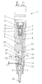
- a solenoid controlled direct injection fuel injector 1 (hereinafter referred to as injector) for one not Accumulated fuel injection system or common rail system a multi-cylinder internal combustion engine exposes itself a solenoid valve 2 arranged on the head side of the injector, one underlying control piston 3 with valve piston 4 and one spring-loaded nozzle needle 5 together.
- An inlet line 6 opens into a valve piston 4 surrounding Annulus 7, from which a feed line 8 to extends to the nozzle needle 5.
- the valve piston 4 closes during the injection line the supply line 6 or interrupts the flow connection from the feed line 6 to the feed line 8 into a pressure chamber 9 surrounding the nozzle needle 5 flows.
- the system-pressurized control piston 3 limits one Control room 10, which is connected via a line 11 Inlet throttle 12 is connected to the inlet line 6. Of the Control room 10 is via an outlet throttle 13 by the solenoid valve 2 can be opened, relieved.
- the nozzle needle 5 is guided by a nozzle needle spring guided in the spring chamber 14 15 pressed onto their valve seat 16.
- the spring chamber 14 is one due to the larger diameter part 17a Stepped bore 17 formed, while the smaller part one Pressure chamber 18 limited in which a pressurizable piston 19 is guided longitudinally, with one in the spring chamber 14 protruding needle stop pin 20 firmly connected is.
- the piston 19 is slightly larger in diameter the needle stop pin 20.
- the needle stop pin 20 has a shoulder 21 for support the nozzle needle spring 15. This shoulder 21 is perfect Function of fuel injector 1 at the transition 17b of the stepped bore 17. On the back of the nozzle needle 5 there is a valve plate 22 on which the nozzle needle spring is located 15 supports.
- the nozzle needle spring 15 presses the nozzle needle 5 and on the other hand the valve stop pin 20 on the respective Seat, in this position the nozzle needle 5 and the needle stop pin 20 have a defined distance x of at least corresponds to the maximum opening stroke of the nozzle needle 5.
- the pressure chamber 18 containing the piston 19 and that to the nozzle needle 5 leading supply line 8 are through a acting as a throttle Cross line 23 connected to each other.
- a throttling line connection branches from the feed line 8 24 from the low pressure side of the fuel injection system leads.
- the throttling line connection 24 and the throttled cross line 23 are coaxial to each other for manufacturing reasons arranged and cross the feed line as a through hole 8.
- the valve housing of the fuel injector 1 only with one operation up to the pressure room 18 are pierced.
- the line connection 24 opens a return line 25 with the open solenoid valve 1 with the control room 10 is connected.
- a malfunction occurs after the usual injection, be it e.g. a jamming of the control piston 3 when open Piston valve 4 and the nozzle needle no longer closes, builds up in the pressure chamber 18 with increasing injection duration Pressure on.
- the pressure in the pressure chamber 18 reaches a value, multiplied by the piston area of the piston 19 is the same size as the product of the system pressure and the nozzle shaft area, is the nozzle needle 5 in the equilibrium of forces and is then replaced by the one lying on the nozzle needle Needle stop pin 20 closed.
- a quantity of fuel therefore flows into the pressure chamber 18 and into a proportional amount of fuel by the time Nozzle holes.
- the maximum amount of fuel, where the nozzle closes automatically, from the system pressure independently.
Landscapes
- Engineering & Computer Science (AREA)
- Chemical & Material Sciences (AREA)
- Combustion & Propulsion (AREA)
- Mechanical Engineering (AREA)
- General Engineering & Computer Science (AREA)
- Physics & Mathematics (AREA)
- Fluid Mechanics (AREA)
- Fuel-Injection Apparatus (AREA)
Abstract
Description
Claims (6)
- Speichereinspritzsystem für eine mehrzylindrige Brennkraftmaschine mit magnetventilgesteuerten direkteinspritzenden Kraftstoffeinspritzventilen, mit einer in jedem Ventilgehäuse zu einer federbelasteten Düsennadel führenden und durch einen Steuerkolben mit Ventilfunktion absperrbaren Zuführleitung, mit einer in einem Federraum sich abstützenden und die Düsennadel auf ihren Nadelsitz drückenden Düsennadelfeder, ferner mit einem auf der Rückseite des unter Systemdruck stehenden Steuerkolbens angeordneten Steuerraum sowie einem mit diesem zusammenwirkenden Magnetventil, durch das der Steuerraum mit einer Entlastungsleitung verbindbar und gleichzeitig die Absperrung der zur Düsennadel führenden Zuführleitung aufhebbar ist, welche über eine drosselnde Leitungsverbindung mit der Niederdruckseite in Verbindung steht,
dadurch gekennzeichnet,
daß die Düsennadel (5) und der Steuerkolben (3) räumlich voneinander getrennt sind und daß sich an den Federraum (4) ein durchmessermäßig kleinerer Druckraum (18) anschließt, in dem ein den Druckraum (18) von dem Federraum (4) trennender Kolben (19) längsverschiebbar geführt ist, wobei eine Verbindung des Druckraumes (18) mit der Zuführleitung (8) derart ausgebildet ist, daß bei einer auf einer Funktionsstörung des Kraftstoffeinspritzventiles (1) beruhenden unzulässig langen Systemdruckbeaufschlagung der Zuführleitung (8) der Druckraum (18) und damit der Kolben (19) mit Systemdruck beaufschlagt wird und der Kolben (19) in Schließrichtung auf die Düsennadel (5) einwirkt. - Speichereinspritzsystem nach Anspruch 1,
dadurch gekennzeichnet,
daß eine von der Zuführleitung (8) stromab des Steuerkolbens (3) abzweigende und als Drossel wirkende Querleitung (23) in den von dem Kolben (19) begrenzten Druckraum (18) mündet. - Speichereinspritzsystem nach Anspruch 1,
dadurch gekennzeichnet,
daß der Kolben (19) mit einem in den Federraum (14) hineinragenden Nadelanschlagstift (20) verbunden ist, welcher in seiner Ausgangsstellung mindestens einen den maximalen Öffnungshub der Düsennadel (5) zulassenden Abstand aufweist. - Speichereinspritzsystem nach Anspruch 3,
dadurch gekennzeichnet,
daß der Nadelanschlagstift (20) von der Düsennadelfeder (15) umgeben ist, die sich einerseits an der Düsennadel (5) und andererseits an einer Schulter (21) am Nadelanschlagstift (20) abstützt. - Speichereinspritzsystem nach einem der vorhergehenden Ansprüche,
dadurch gekennzeichnet,
daß der Schaftdurchmesser der Düsennadel (5) kleiner ist als der Durchmesser des Kolbens (19). - Speichereinspritzsystem nach einem der vorhergehenden Ansprüche,
dadurch gekennzeichnet,
daß eine mit der Niederdruckseite verbundene drosselnde Leitungsverbindung (24) und eine gedrosselte Querleitung (23) koaxial zueinander liegen und als Durchgangsbohrung die Zuführleitung (8) kreuzen.
Applications Claiming Priority (2)
| Application Number | Priority Date | Filing Date | Title |
|---|---|---|---|
| DE19717419A DE19717419C1 (de) | 1997-04-25 | 1997-04-25 | Speichereinspritzsystem für eine mehrzylindrige Brennkraftmaschine mit magnetventilgesteuerten Kraftstoffeinspritzventilen |
| DE19717419 | 1997-04-25 |
Publications (2)
| Publication Number | Publication Date |
|---|---|
| EP0874153A2 true EP0874153A2 (de) | 1998-10-28 |
| EP0874153A3 EP0874153A3 (de) | 2000-11-02 |
Family
ID=7827681
Family Applications (1)
| Application Number | Title | Priority Date | Filing Date |
|---|---|---|---|
| EP98105360A Withdrawn EP0874153A3 (de) | 1997-04-25 | 1998-03-25 | Speichereinspritzsystem für eine mehrzylindrige Brennkraftmaschine mit magnetventilgesteuerten Kraftstoffeinspritzventilen |
Country Status (3)
| Country | Link |
|---|---|
| US (1) | US5988533A (de) |
| EP (1) | EP0874153A3 (de) |
| DE (1) | DE19717419C1 (de) |
Families Citing this family (8)
| Publication number | Priority date | Publication date | Assignee | Title |
|---|---|---|---|---|
| GB0008598D0 (en) * | 2000-04-07 | 2000-05-31 | Delphi Tech Inc | Fuel system |
| FI114502B (fi) * | 2001-05-14 | 2004-10-29 | Waertsilae Finland Oy | Polttoaineen ruiskutusjärjestely |
| KR101211331B1 (ko) | 2010-12-28 | 2012-12-11 | 현대중공업 주식회사 | 전자제어 연료분사밸브 |
| KR101165541B1 (ko) | 2010-12-28 | 2012-07-16 | 현대중공업 주식회사 | 전자제어 연료분사밸브 |
| US9181893B2 (en) | 2010-12-28 | 2015-11-10 | Hyundai Heavy Industries Co., Ltd. | Electronically controlled fuel injection valve |
| KR101162883B1 (ko) | 2010-12-28 | 2012-07-05 | 현대중공업 주식회사 | 전자제어 연료분사밸브 |
| CN103339369B (zh) * | 2010-12-28 | 2015-07-01 | 现代重工业株式会社 | 电子控制燃料喷射阀 |
| KR101222411B1 (ko) | 2010-12-28 | 2013-01-14 | 현대중공업 주식회사 | 전자제어 연료분사밸브 |
Citations (2)
| Publication number | Priority date | Publication date | Assignee | Title |
|---|---|---|---|---|
| US5109822A (en) | 1989-01-11 | 1992-05-05 | Martin Tiby M | High pressure electronic common-rail fuel injection system for diesel engines |
| DE19612738A1 (de) | 1995-04-05 | 1996-10-10 | Avl Verbrennungskraft Messtech | Speichereinspritzsystem für Brennkraftmaschinen |
Family Cites Families (6)
| Publication number | Priority date | Publication date | Assignee | Title |
|---|---|---|---|---|
| CH447714A (de) * | 1967-03-22 | 1967-11-30 | Huber Robert | Sicherheitsvorrichtung an elektromagnetischen Einspritzventilen von Verbrennungsmotoren |
| CS215203B1 (en) * | 1980-12-09 | 1982-08-27 | Jaromir Indra | Injection device of the ignition engine |
| FR2502701A1 (fr) * | 1981-03-26 | 1982-10-01 | Renault Vehicules Ind | Systeme d'injection a pilotage de l'injecteur, pour un moteur a combustion interne |
| DE3119050A1 (de) * | 1981-05-05 | 1982-11-18 | Gebrüder Sulzer AG, 8401 Winterthur | "brennstoffeinspritzvorrichtung mit elektromagnetisch betaetigtem umschaltventil" |
| JPS61187567A (ja) * | 1985-02-15 | 1986-08-21 | Kawasaki Heavy Ind Ltd | ガス噴射弁 |
| US5526791A (en) * | 1995-06-07 | 1996-06-18 | Diesel Technology Company | High-pressure electromagnetic fuel injector |
-
1997
- 1997-04-25 DE DE19717419A patent/DE19717419C1/de not_active Expired - Fee Related
-
1998
- 1998-03-25 EP EP98105360A patent/EP0874153A3/de not_active Withdrawn
- 1998-04-22 US US09/064,380 patent/US5988533A/en not_active Expired - Fee Related
Patent Citations (2)
| Publication number | Priority date | Publication date | Assignee | Title |
|---|---|---|---|---|
| US5109822A (en) | 1989-01-11 | 1992-05-05 | Martin Tiby M | High pressure electronic common-rail fuel injection system for diesel engines |
| DE19612738A1 (de) | 1995-04-05 | 1996-10-10 | Avl Verbrennungskraft Messtech | Speichereinspritzsystem für Brennkraftmaschinen |
Also Published As
| Publication number | Publication date |
|---|---|
| US5988533A (en) | 1999-11-23 |
| DE19717419C1 (de) | 1998-07-30 |
| EP0874153A3 (de) | 2000-11-02 |
Similar Documents
| Publication | Publication Date | Title |
|---|---|---|
| DE19519192C1 (de) | Einspritzventil | |
| DE60103896T2 (de) | Vorrichtung zum regeln eines gasdurchflusses | |
| DE19706467C1 (de) | Speichereinspritzsystem für eine mehrzylindrige Brennkraftmaschine | |
| DE69613192T2 (de) | Elektromagnetisch betätigtes miniverstärkerschiebeventil | |
| EP0657644B1 (de) | Kraftstoffeinspritzeinrichtung für Brennkraftmaschinen | |
| DE1933489A1 (de) | Brennstoff-Einspritzventil mit elektromagnetischer Betaetigung | |
| DE4332119A1 (de) | Kraftstoffeinspritzeinrichtung für Brennkraftmaschinen | |
| EP2049787A1 (de) | Injektor für ein kraftstoffeinspritzsystem | |
| DE69124228T2 (de) | Elektronische Hochdruckeinspritzkraftstoffleitung für Dieselmotoren | |
| EP0657643B1 (de) | Kraftstoffeinspritzeinrichtung für Brennkraftmaschinen | |
| CH671609A5 (de) | Vorrichtung zum verhindern eines uebermaessigen durchflusses von gasfoermigem brennstoff durch eine einspritzduese eines dieselmotors. | |
| EP0959243A1 (de) | Steuerventil für Kraftstoffeinspritzventil | |
| EP0976924B1 (de) | Einspritzventil mit einem Servoventil | |
| DE19748999C2 (de) | Magnetventilgesteuerter Injektor für ein Speichersystem einer mehrzylindrigen Brennkraftmaschine | |
| EP1144862B1 (de) | Hochdruckkraftstoffinjektor mit hydraulisch gesteuertem steuerschieber | |
| DE10031579A1 (de) | Druckgesteuerter Injektor mit Vario-Register-Einspritzdüse | |
| DE19741850A1 (de) | Eispritzventil | |
| DE10245151B4 (de) | Kraftstoffeinspritzvorrichtung | |
| EP1718862B1 (de) | Brennstoffeinspritzventil für verbrennungskraftmaschinen | |
| EP0874153A2 (de) | Speichereinspritzsystem für eine mehrzylindrige Brennkraftmaschine mit magnetventilgesteuerten Kraftstoffeinspritzventilen | |
| EP1097303A2 (de) | Kraftstoffeinspritzanlage | |
| CH686845A5 (de) | Steueranordnung fuer ein Einspritzventil fuer Verbrennungskraftmaschinen. | |
| DE10031582A1 (de) | Druckgesteuerter Injektor mit gesteuerter Düsennadel | |
| EP1373706A1 (de) | Einspritzventil | |
| EP1939441A2 (de) | Kraftstoffinjektor |
Legal Events
| Date | Code | Title | Description |
|---|---|---|---|
| PUAI | Public reference made under article 153(3) epc to a published international application that has entered the european phase |
Free format text: ORIGINAL CODE: 0009012 |
|
| AK | Designated contracting states |
Kind code of ref document: A2 Designated state(s): DE FR GB IT |
|
| AX | Request for extension of the european patent |
Free format text: AL;LT;LV;MK;RO;SI |
|
| RAP1 | Party data changed (applicant data changed or rights of an application transferred) |
Owner name: DAIMLERCHRYSLER AG |
|
| PUAL | Search report despatched |
Free format text: ORIGINAL CODE: 0009013 |
|
| AK | Designated contracting states |
Kind code of ref document: A3 Designated state(s): AT BE CH DE DK ES FI FR GB GR IE IT LI LU MC NL PT SE |
|
| AX | Request for extension of the european patent |
Free format text: AL;LT;LV;MK;RO;SI |
|
| 17P | Request for examination filed |
Effective date: 20001028 |
|
| AKX | Designation fees paid |
Free format text: DE FR GB IT |
|
| STAA | Information on the status of an ep patent application or granted ep patent |
Free format text: STATUS: THE APPLICATION HAS BEEN WITHDRAWN |
|
| 18W | Application withdrawn |
Withdrawal date: 20020829 |