EP0874222A2 - Allwetter-Navigations-Display für Hubschrauber - Google Patents
Allwetter-Navigations-Display für Hubschrauber Download PDFInfo
- Publication number
- EP0874222A2 EP0874222A2 EP98106199A EP98106199A EP0874222A2 EP 0874222 A2 EP0874222 A2 EP 0874222A2 EP 98106199 A EP98106199 A EP 98106199A EP 98106199 A EP98106199 A EP 98106199A EP 0874222 A2 EP0874222 A2 EP 0874222A2
- Authority
- EP
- European Patent Office
- Prior art keywords
- display
- flight
- mode
- lsk
- navigation
- Prior art date
- Legal status (The legal status is an assumption and is not a legal conclusion. Google has not performed a legal analysis and makes no representation as to the accuracy of the status listed.)
- Granted
Links
Images





Classifications
-
- G—PHYSICS
- G01—MEASURING; TESTING
- G01C—MEASURING DISTANCES, LEVELS OR BEARINGS; SURVEYING; NAVIGATION; GYROSCOPIC INSTRUMENTS; PHOTOGRAMMETRY OR VIDEOGRAMMETRY
- G01C23/00—Combined instruments indicating more than one navigational value, e.g. for aircraft; Combined measuring devices for measuring two or more variables of movement, e.g. distance, speed or acceleration
Definitions
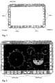
- the symbols are shown on a redundant display with a usable display area of 284mm x 160mm.
- the display area of the Displays are surrounded by a display frame on which various display and control elements are housed.
- the left and right side of the display frame has 7 push buttons each or LSK's (Line Select Keys). Align the functions of the LSK's depending on the operating mode (NAV, APP or HVR) of the display system. An overview of the functions can be found in Table 2.
- the Shift key is located on the upper left display frame. By pressing the Shift key, the functions of the left FFK's and LSK's can be placed on the right side. This measure ensures redundancy of each individual key function, so that the failure of an individual FFK or LSK key cannot lead to the loss of function. After pressing the Shift key again, the functions are put back on the keys on the left side of the display.
- the PFD format is shown on the right side of the display.
- This Format includes the display of the ADI (artificial horizon), the airspeed, the barometric altitude, the vertical speed, the power setting, the DME display (distance to the next or selected waypoint) and several digital information such as the speed over ground, the set air pressure, the heading and course, as well as various status and warning messages.
- the representation of the artificial horizon ADI (Attitude Director Indicator) takes place centrally in the PFD format. It is used to assess the pitch and roll position of the helicopter.
- the helicopter reference or the helicopter longitudinal axis is defined by two yellow lines or by a yellow circle in the center of the ADI.
- the scale of the pitch axis is divided into 5 ° sections, with the area over the horizon line is blue or the area under the horizon line is brown is.
- the scale marking of the pitch axis is at intervals of 10 ° appropriate.
- the roll scale (fixed) is located above the ADI with a Display range of ⁇ 60 °.
- the scale is divided into 10 ° steps, with a a short tick every 10 ° and a long tick every 30 ° is displayed.
- the rollage is indicated by a small yellow triangle on the inside of the Scale displayed (Skypointer).
- the barometric flight altitude is displayed in accordance with the standard T arrangement to the right of the ADI, in a slightly elevated position on a circular scale.
- One revolution of the pointer corresponds to one barometric Difference in altitude of 1000 feet.
- the scale of the circle is in one Split the way that the altimeter pointer in the stationary IFR cruise can point vertically upwards.
- the division of the circle corresponds to height sections of 20 feet, with a short tick every 20 feet and one long tick mark is displayed every 100 feet.
- the scale label is in Installed 100 feet apart.
- the barometric display is displayed Flight height additionally the analog display of the decision height and the Radar height shown.
- the symbol of the Floor marking (brown hatched line) with respect to the barometric Flight altitude can be calculated and displayed. Extends over the floor marking the blue marked arc area of the decision height.
- the barometric altimeter pointer is shown in Amber shown as soon as the helicopter is within the decision height.
- the barometric altitude is displayed digitally in the center of the circle. Under the digital display window, the label ALT (Altitude) indicates the parameter shown.
- the vertical speed is shown on the right below the ADI on an arc.
- the maximum displayed values for descent and climb correspond to ⁇ 3000 feet / minute, with the non-linear scale being a larger one Spreads in the range - 1000 feet / minute to +1000 feet / minute provides.
- the Subdivision of the circular arc corresponds to the range between - 1000 Feet / minute and +1000 feet / minute a sink rate or climb rate of 100 Feet / minute, with a short tick every 100 feet / minute and a long one Graduation is displayed every 500 feet / minute. Outside of this area the short tick marks are every 500 feet / minute and the long tick marks displayed every 1000 feet / minute.
- the pointer of the variometer is in horizontal flight horizontally to the left. In the center of the arc is complementary the vertical speed is displayed digitally for analog display.
- the power setting (torque of engine 1 and 2) is shown on the left below the ADI on a circular arc.
- the scale ranges from 0% to 130% torque and is divided in such a way that the power pointer points horizontally to the right during the cross-country flight.
- the power setting scale is divided into 10% sections, with a short tick every 10% and a long tick every 50%.
- the scale label is attached at intervals of 50%. If the torque values of engine 1 and 2 differ, the torque pointer splits into two separate pointers. The pointers are with 1 for engine 1 and 2nd marked for engine 2. A red line shows the respective performance limit based on the torque value.
- the parameters of airspeed, altitude, vertical speed and the power setting are shown on circular displays. This is associated with a quick understanding of deviations from Target value, since even small changes in the angle of the pointer in the peripheral field of view of the pilot.
- the scales of the four displays are in one Arranged in such a way that the two upper pointers vertically upwards or the has the two lower hands pointing horizontally. This symmetrical arrangement again makes it easier for pilots to grasp deviations from the target value.
- the HSI format is shown on the left side of the display.
- This Format includes the display of the gyrocompass, the direction of flight, the Radio navigation, the flight route and various map information.
- the representation The HSI format can be used in both sector and rose mode respectively.
- VFR chart Under the compass rose, three different types of cards (VFR chart, IFR chart, road map) can be selected, which improves navigation in both instrument and visual flight.
- the center of the compass sector corresponds to the current helicopter position, which is reflected by an aircraft symbol. Similar to Rose mode, three navigation pointers are also used in Sector mode shown the information according to the activation of the navigation systems via bearing and storage to the selected waypoint and to Deliver flight route. The direction to the next waypoint and the selected one Heading is also indicated here by a blue triangle or by the green one Heading bug displayed.
- the pilot can view the displays using the functions of the LSK's (Line Select Key) on the AWRH display according to the requirements of the flight mission configure. 14 LSK's are available on the display, whereby in NAV mode (normal operation) only the seven LSK's on the left side of the display are assigned functions.
- the three upper LSK's are used to connect the navigation pointer to the Navigation sources.
- the navigation sources are two NAV's, an ADF and GPS navigation is available.
- each of the three Navigati ons baler be switched to each of the four navigation sources.
- On the The LSK's label is the respective logo of the navigation pointer including the Frequency and the identification code mapped.
- LSK HSPL can be displayed in the HSI format hospital positions relative to the helicopter position.
- the label of the LSK is labeled ON (when the function is on) or OFF (when the function is off).
- a map background can be selected in HSI format.
- the label of the LSK is with VFR / IFR / ROAD referred to, the respective lettering of the corresponding card lights up brightly after a card selection.
- the HSI format can be switched between rose and sector mode.
- the label of the LSK is with ROSE / SEC referred to, the lettering ROSE in rose mode or SEC lights up brightly in sector mode.
- the operating mode APP is used in particular in the sensor flight of the AWRH helicopter.
- the entire display area is used for a display format to show the flight guidance and navigation symbols. All parameters of the NAV mode are also displayed in the APP mode.
- the display philosophy of the two modes is identical in order to minimize the adaptation of the pilot when changing.
- the artificial horizon is shown centrally on the display.
- the helicopter reference or the helicopter longitudinal axis is defined by two green angled lines or by a green circle in the center of the display.
- a yellow line is used as the horizon line, with at both ends 0 is designated.
- Further lines of the pitch scale are hidden in horizontal flight in order to keep the screen center free from unnecessary lines. With larger pitch positions of ⁇ 10 ° further lines of the pitch scale appear.
- This scale is divided into 5 ° sections, with a short graduation every 5 ° and a long graduation including the scale inscription every 10 °. At both ends of the lines, short lines point at right angles towards the horizon reference.
- the scroll scale (fixed) is located above the AD with a display area of only ⁇ 30 °.
- the scale is divided into 10 ° steps, with a small one Graduation every 10 ° and a large graduation every 30 ° is displayed.
- the roll scale is symmetrical to ⁇ 60 ° extended on both sides.
- the rollage is indicated by a small green triangle displayed on the inside of the scale (Skypointer). Should the helicopter equipped with a flight director, the horizontal is displayed and vertical flight director bars in the center of the ADI.
- the flight direction is shown (Heading scale) below the ADI as a horizontal treadmill.
- the information the current flight direction is a digital value at a central position the heading scale.
- the three navigation pointers, the waypoint pointer and the heading bug the heading scale at the corresponding DF position.
- the symbol of the next waypoint becomes the DME information of the distance to the next waypoint.
- the symbol comes to rest on the left end of the scale, as long as a left curve of the corresponds to the shortest change of direction to the corresponding bearing position.
- Corresponding the respective symbol to the right of the scale comes to rest as long as a right turn corresponds to the shortest change of direction. Over the tilted
- the symbol of the next waypoint is next to the distance information the bearing direction is also displayed.
- the pilot of the AWRH helicopter has one for arrival and departure Obstacle symbols available. This symbolism is meant for the pilot within of the obstacle backdrop open up the opportunity to overcome obstacles in time identify and dodge them.
- an obstacle network was selected as an obstacle symbol.
- This network is generated in real time from the information from a radar sensor determined and shown on the display as rectangular meshes.
- the Rectangular mesh shape has been in favor of better orientation preferred to a square stitch when cornering.
- the color of the Net depends on the net height (or obstacle height) in Relation to the helicopter height, as well as according to the flight vector of the helicopter. Network points that will exceed the current helicopter position shown in red. All remaining network points are in a green hue displayed. This color division into critical and uncritical obstacles makes the pilot's task considerably easier when choosing the flight path.
- the height of the net over the obstacles corresponds to the set one Decision Height.
- the safety distance between the obstacles remains and the network can be freely selected for the pilot.
- the Network rise in front of an obstacle
- the direction and speed of the flight involved When flying at low altitude above the net Network lines at a greater distance from the helicopter in favor hidden for a better overview. Network points shown in red remain received regardless of distance.
- the pilot is in operational mode as flight guidance symbols during approach and departure APP a spatial flight tunnel of the target path is shown on the display of the helicopter.
- the advantage of displaying a spatial flight path lies in the fact that not only the current storage of the target course is displayed (as with a cross pointer instrument), but a look into the future flight route is possible. This has an effect in particular on curved approaches or also on short approaches view in the future particularly positive.
- the tunnel is formed by a series of tunnel gates. Each tunnel gate has a rectangular cross-section with 30m horizontal width and 20m vertical height. The distance between two gates is constant and is 70m. To make the pilot's position of the helicopter between the tunnel entrance and tunnel exit clear, there is a small line marking on the right-hand tunnel post. The position of the line marking corresponds to the current position of the helicopter in the tunnel, a high position of the marking corresponding to the beginning of the tunnel and a low position of the marking corresponding to the end of the tunnel.
- the pilot can view the displays using the functions of the LSK's (Line Select Key) on the AWRH display according to the requirements of the flight mission configure. 14 LSK's are available on the display, whereby in APP mode (normal operation) only the seven LSK's on the left side of the display Functions are occupied.
- the assignment of the three upper LSKs corresponds to the assignment of the three upper LSK's in NAV mode. They are used to activate the navigation pointers on the navigation sources.
- the operating and display concept corresponds the NAV mode.
- the label of the LSK is labeled ON (with ADI switched on) or OFF (with ADI switched off).
- the arrival and departure tunnels can be switched on or off.
- the label of the LSK is labeled ON (when the tunnel is on) or OFF (when the tunnel is off).
- the obstacle network can be switched on or off.
- the label of the LSK is labeled ON (when the network is switched on) and OFF (when the network is switched off).
- the LSK MAP / RAD can be switched between a three-dimensional map and a radar sensor image.
- Both displays are shown in the APP mode as a background image behind the flight guidance and navigation symbols. The perspective of both representations is identical. It covers a range of 70 ° horizontally and 40 ° vertically from the current helicopter position in the direction of flight.
- the three-dimensional map is used for spatial orientation outside the obstacle backdrop. This type of display greatly illustrates the terrain situation and the airspace structure. When approaching the obstacle backdrop, the pilot will usually switch to the radar sensor image, since only in this mode is it possible to identify all obstacles. Both the three-dimensional map and the radar sensor image can be overlaid with the obstacle network.
Landscapes
- Engineering & Computer Science (AREA)
- Radar, Positioning & Navigation (AREA)
- Remote Sensing (AREA)
- Aviation & Aerospace Engineering (AREA)
- Physics & Mathematics (AREA)
- General Physics & Mathematics (AREA)
- Navigation (AREA)
- Traffic Control Systems (AREA)
Abstract
Description
- Fig. 1
- ein AWRH-Display mit FFK's, LSK's, Drehgebern und Shift-Taste,
- Fig. 2
- ein AWRH-Display im NAV Betriebsmodus mit den Formaten PFD und HSI
- Fig. 3
- die ADI Darstellung im Betriebsmodus NAV


- Fig. 4
- die IAS Darstellung im Betriebsmodus
- Fig. 5
- die ALT Darstellung im Betriebsmodus
- Fig. 6
- die Darstellung der vertikalen Geschwindigkeit im Betriebsmodus
- Fig. 7
- die Darstellung der Leistungseinstellung im Betriebsmodus
- Fig. 8:
- die Zeigerstellungen des PFD Formates im stationären Reiseflug
- Fig. 9:
- das HSI Format im Rose Modus
- Fig. 10
- das HSI Format im Sector Modus
- Fig. 11
- die LSK's in NAV Modus
- Fig. 12
- das "NAV"-Display mit hinterlegter Karte
- Fig. 13
- das AWRH-Display im APP Betriebsmodus
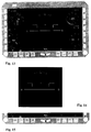
- Fig. 14
- die ADI Darstellung im Betriebsmodus
- Fig. 15
- die Darstellung der Flugrichtungsskala mit digitaler Headingangabe
- Fig. 16
- die Hindernissymbolik im Betriebsmodus
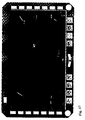
- Fig. 17
- den Anflugtunnel im Betriebsmodus
- Fig. 18
- den Anflugtunnel im Betriebsmodus
- Fig. 19
- die LSK's im APP Modus.


Claims (6)
- Allwetter-Navigations-Display für Hubschrauber mit einer elektronischen Bildschirmanzeige-Vorrichtung, dadurch gekennzeichnet, daß die elektronisch ansteuerbare Displayfläche von einem Rahmen umgeben ist, auf dessen Unterkante Bedienungstasten mit festen Funktionen und auf dessen Seitenkanten Bedienungstasten mit variablen Funktionen angeordnet sind, wobei die Werte der ersteren mit an den Ecken des Rahmens angeordneten Drehgebern einstellbar sind und die aktuelle Funktion der letzteren auf dem Display angezeigt werden.
- Allwetter-Navigationsdisplay nach Anspruch 1, dadurch gekennzeichnet, daß der Inhalt der Displayfläche beim Normalflug im Modus NAV (Navigationsmodus) auf der linken Hälfte aus den Angaben über die HSI-Werte (Horizontal Situation Indicator) und auf der rechten Sete aus den Angaben über die PFD-Werte /Primary Flight Display) bestehen und daß die Hälften über eine SHIFT-Taste im Dsplay-Rahmen vertauschbar sind.
- Allwetter-Navigationsdisplay nach Anspruch 2, dadurch gekennzeichnet, daß die Angaben über die HSI-Werte (Horizontal Situation Indicator) mit einer Landkarte unterlegbar sind.
- Allwetter-Navigationsdisplay nach Anspruch 2 oder 3, dadurch gekennzeichnet, daß die wesentlichen Anzeigen aus Rund-Anzeigen bestehen und die Normalwerte derselben in horizontalen bzw vertikalen Zeigerstellungen dargestellt sind.
- Allwetter-Navigationsdisplay nach einem der vorhergehenden Ansprüche, dadurch gekennzeichnet, daß der Inhalt der Displayfläche beim Anflug im Modus APP (Approach Modus) aus den seitlich an den Rand gerückten PFD-Anzeigen und einer im Mittelbereich dargestellten, für den Anflug wesentlichen zusätzlichen Anzeigen über geortete Hindernisse und/oder Flugtunnels besteht.
- Allwetter-Navigationsdisplay nach Anspruch 5, dadurch gekennzeichnet, daß der Inhalt der zentralen Displayfläche über die mit Hilfe von Angaben auf demDisplay bezeichneten seitlichen Funktionstasten auswählbar ist..
Applications Claiming Priority (2)
| Application Number | Priority Date | Filing Date | Title |
|---|---|---|---|
| DE19716941 | 1997-04-23 | ||
| DE19716941A DE19716941C2 (de) | 1997-04-23 | 1997-04-23 | Allwetter-Navigations-Display für Hubschrauber |
Publications (3)
| Publication Number | Publication Date |
|---|---|
| EP0874222A2 true EP0874222A2 (de) | 1998-10-28 |
| EP0874222A3 EP0874222A3 (de) | 2000-06-28 |
| EP0874222B1 EP0874222B1 (de) | 2003-02-19 |
Family
ID=7827366
Family Applications (1)
| Application Number | Title | Priority Date | Filing Date |
|---|---|---|---|
| EP98106199A Expired - Lifetime EP0874222B1 (de) | 1997-04-23 | 1998-04-04 | Allwetter-Navigations-Display für Hubschrauber |
Country Status (2)
| Country | Link |
|---|---|
| EP (1) | EP0874222B1 (de) |
| DE (2) | DE19716941C2 (de) |
Cited By (1)
| Publication number | Priority date | Publication date | Assignee | Title |
|---|---|---|---|---|
| EP1154236A3 (de) * | 2000-05-10 | 2004-01-14 | EADS Deutschland Gmbh | Flugführungsanzeiger |
Families Citing this family (2)
| Publication number | Priority date | Publication date | Assignee | Title |
|---|---|---|---|---|
| GB2447967B (en) * | 2007-03-30 | 2012-03-28 | Ge Aviat Systems Ltd | Aircraft displays and display arrangements |
| CN102522064B (zh) * | 2011-12-14 | 2014-01-29 | 中国航空无线电电子研究所 | 具有彩色oled显示屏的座舱控制器 |
Family Cites Families (5)
| Publication number | Priority date | Publication date | Assignee | Title |
|---|---|---|---|---|
| US4845495A (en) * | 1988-02-17 | 1989-07-04 | Allied-Signal Inc. | Integrated avionics control and display arrangement |
| GB9113279D0 (en) * | 1991-06-19 | 1991-08-07 | Marconi Instruments Ltd | A system controlled by manually operable keys |
| CA2099953C (fr) * | 1992-07-24 | 2006-11-14 | Engin Oder | Procede et dispositif d'assistance au pilotage d'un aerodyne a partir d'un ensemble volumineux de documents stockes en memoire |
| DE4307367A1 (de) * | 1993-03-09 | 1994-09-15 | Bosch Gmbh Robert | Anzeige- und Bedieneinrichtung, insbesondere für Kraftfahrzeuge |
| US5416705A (en) * | 1993-04-19 | 1995-05-16 | Honeywell Inc. | Method and apparatus for use of alphanumeric display as data entry scratchpad |
-
1997
- 1997-04-23 DE DE19716941A patent/DE19716941C2/de not_active Expired - Fee Related
-
1998
- 1998-04-04 EP EP98106199A patent/EP0874222B1/de not_active Expired - Lifetime
- 1998-04-04 DE DE59807224T patent/DE59807224D1/de not_active Expired - Lifetime
Cited By (2)
| Publication number | Priority date | Publication date | Assignee | Title |
|---|---|---|---|---|
| EP1154236A3 (de) * | 2000-05-10 | 2004-01-14 | EADS Deutschland Gmbh | Flugführungsanzeiger |
| US7365705B2 (en) | 2000-05-10 | 2008-04-29 | Eads Deutschland Gmbh | Flight control display |
Also Published As
| Publication number | Publication date |
|---|---|
| EP0874222A3 (de) | 2000-06-28 |
| DE59807224D1 (de) | 2003-03-27 |
| DE19716941A1 (de) | 1998-10-29 |
| EP0874222B1 (de) | 2003-02-19 |
| DE19716941C2 (de) | 2000-09-21 |
Similar Documents
| Publication | Publication Date | Title |
|---|---|---|
| EP0697098B1 (de) | Verfahren zur darstellung von flugführungsinformationen | |
| DE3850088T2 (de) | Integriertes, primäres Fluganzeigeinstrument. | |
| DE60222503T2 (de) | Flugbahninformationsanordnungen, Computerprogrammprodukte und Verfahren zum Anzeigen einer Flugbahnabweichungsinformation basierend auf einer Navigationssystemgüte | |
| DE69712185T2 (de) | Vorrichtung und verfahren für flugzeugnavigationshilfe | |
| DE69117890T2 (de) | Sichtanzeigeanlagen und -systeme | |
| DE69910344T2 (de) | Cockpitanzeige mit dreidimensionaler Flugbahnabweichungssymbolik | |
| DE69101256T2 (de) | Primäre Fluganzeige zum Darstellen von Entscheidungsvorschlagsinformation, die von einem Verkehrswarn- und Koalisionsschutzsystem geliefert wird. | |
| US7308343B1 (en) | Navigational instrument, method and computer program product for displaying ground traffic information | |
| US7194342B1 (en) | Navigational instrument, method and computer program product for displaying ground traffic information | |
| DE69617745T2 (de) | Dreidimensionales anzeigegerät für seitliche verlagerung | |
| EP0418558B1 (de) | Verfahren und Einrichtung zur Darstellung von Flugführungsinformation | |
| DE69309179T2 (de) | Verfahren für Navigationshilfe | |
| DE2817051A1 (de) | Anzeigevorrichtung, insbesondere fuer luftfahrzeuginstrumentierung | |
| DE69625835T2 (de) | Steueranordnung eines handgesteuerten Flugzeugsystemes mit insbesondere einem Head-Up-Display | |
| EP1972896A2 (de) | Mensch-Maschinen-Interface zur Pilotenunterstützung bei Start und Landung eines Fluggerät bei verminderter Außensicht | |
| EP1109032B1 (de) | Verfahren und System zum Warnen vor Kollisionen zwischen Fluggeräten | |
| DE69712186T2 (de) | Vorrichtung und verfahren für flugzeugnavigationshilfe unter anzeige der verwendeten navigationsinstrumente | |
| EP0874222B1 (de) | Allwetter-Navigations-Display für Hubschrauber | |
| EP2618110B1 (de) | Verfahren und System zur Landehilfe für Helikopter | |
| DE69709486T2 (de) | Horizontalgeschwindigkeitsanzeiger für Drehflügel-Luftfahrzeug | |
| DE1456128A1 (de) | System zum Landen von Luftfahrzeugen | |
| DE1265800B (de) | Flugzeugblindanflug- und -landeanlage | |
| DE2458664C3 (de) | Flugsicherungseinrichtung | |
| DE3546116A1 (de) | Verfahren zur darstellung von soll- und istdaten des flugzustandes vor und waehrend der landung fuer einen piloten | |
| EP0941451A1 (de) | Verfahren und einrichtung zur zielführungsunterstützung eines fahrzeugführers |
Legal Events
| Date | Code | Title | Description |
|---|---|---|---|
| PUAI | Public reference made under article 153(3) epc to a published international application that has entered the european phase |
Free format text: ORIGINAL CODE: 0009012 |
|
| AK | Designated contracting states |
Kind code of ref document: A2 Designated state(s): DE FR GB IT |
|
| AX | Request for extension of the european patent |
Free format text: AL;LT;LV;MK;RO;SI |
|
| 17P | Request for examination filed |
Effective date: 19990219 |
|
| PUAL | Search report despatched |
Free format text: ORIGINAL CODE: 0009013 |
|
| AK | Designated contracting states |
Kind code of ref document: A3 Designated state(s): AT BE CH DE DK ES FI FR GB GR IE IT LI LU MC NL PT SE |
|
| AX | Request for extension of the european patent |
Free format text: AL;LT;LV;MK;RO;SI |
|
| AKX | Designation fees paid |
Free format text: DE FR GB IT |
|
| GRAH | Despatch of communication of intention to grant a patent |
Free format text: ORIGINAL CODE: EPIDOS IGRA |
|
| RAP1 | Party data changed (applicant data changed or rights of an application transferred) |
Owner name: EUROCOPTER DEUTSCHLAND GMBH |
|
| GRAH | Despatch of communication of intention to grant a patent |
Free format text: ORIGINAL CODE: EPIDOS IGRA |
|
| GRAA | (expected) grant |
Free format text: ORIGINAL CODE: 0009210 |
|
| AK | Designated contracting states |
Designated state(s): DE FR GB IT |
|
| REG | Reference to a national code |
Ref country code: GB Ref legal event code: FG4D Free format text: NOT ENGLISH |
|
| REF | Corresponds to: |
Ref document number: 59807224 Country of ref document: DE Date of ref document: 20030327 Kind code of ref document: P |
|
| GBT | Gb: translation of ep patent filed (gb section 77(6)(a)/1977) | ||
| ET | Fr: translation filed | ||
| PLBE | No opposition filed within time limit |
Free format text: ORIGINAL CODE: 0009261 |
|
| STAA | Information on the status of an ep patent application or granted ep patent |
Free format text: STATUS: NO OPPOSITION FILED WITHIN TIME LIMIT |
|
| 26N | No opposition filed |
Effective date: 20031120 |
|
| PGFP | Annual fee paid to national office [announced via postgrant information from national office to epo] |
Ref country code: GB Payment date: 20130326 Year of fee payment: 16 |
|
| PGFP | Annual fee paid to national office [announced via postgrant information from national office to epo] |
Ref country code: DE Payment date: 20130322 Year of fee payment: 16 |
|
| PGFP | Annual fee paid to national office [announced via postgrant information from national office to epo] |
Ref country code: FR Payment date: 20130603 Year of fee payment: 16 |
|
| REG | Reference to a national code |
Ref country code: DE Ref legal event code: R119 Ref document number: 59807224 Country of ref document: DE |
|
| GBPC | Gb: european patent ceased through non-payment of renewal fee |
Effective date: 20140404 |
|
| REG | Reference to a national code |
Ref country code: FR Ref legal event code: ST Effective date: 20141231 |
|
| PG25 | Lapsed in a contracting state [announced via postgrant information from national office to epo] |
Ref country code: DE Free format text: LAPSE BECAUSE OF NON-PAYMENT OF DUE FEES Effective date: 20141101 Ref country code: GB Free format text: LAPSE BECAUSE OF NON-PAYMENT OF DUE FEES Effective date: 20140404 |
|
| REG | Reference to a national code |
Ref country code: DE Ref legal event code: R119 Ref document number: 59807224 Country of ref document: DE Effective date: 20141101 |
|
| PG25 | Lapsed in a contracting state [announced via postgrant information from national office to epo] |
Ref country code: FR Free format text: LAPSE BECAUSE OF NON-PAYMENT OF DUE FEES Effective date: 20140430 |
|
| PGFP | Annual fee paid to national office [announced via postgrant information from national office to epo] |
Ref country code: IT Payment date: 20170424 Year of fee payment: 20 |