EP0874226A1 - Compteur d'eau composé - Google Patents
Compteur d'eau composé Download PDFInfo
- Publication number
- EP0874226A1 EP0874226A1 EP98106125A EP98106125A EP0874226A1 EP 0874226 A1 EP0874226 A1 EP 0874226A1 EP 98106125 A EP98106125 A EP 98106125A EP 98106125 A EP98106125 A EP 98106125A EP 0874226 A1 EP0874226 A1 EP 0874226A1
- Authority
- EP
- European Patent Office
- Prior art keywords
- meter
- insert
- main
- compound water
- impeller
- Prior art date
- Legal status (The legal status is an assumption and is not a legal conclusion. Google has not performed a legal analysis and makes no representation as to the accuracy of the status listed.)
- Granted
Links
- XLYOFNOQVPJJNP-UHFFFAOYSA-N water Substances O XLYOFNOQVPJJNP-UHFFFAOYSA-N 0.000 title claims abstract description 38
- 150000001875 compounds Chemical class 0.000 title claims description 21
- 238000011144 upstream manufacturing Methods 0.000 claims description 8
- 239000004020 conductor Substances 0.000 claims description 6
- 238000010276 construction Methods 0.000 claims description 2
- 239000002131 composite material Substances 0.000 description 6
- 230000008901 benefit Effects 0.000 description 3
- 238000013461 design Methods 0.000 description 3
- 238000005259 measurement Methods 0.000 description 2
- 230000009467 reduction Effects 0.000 description 2
- 238000012549 training Methods 0.000 description 2
- 241000256251 Spodoptera frugiperda Species 0.000 description 1
- 230000005540 biological transmission Effects 0.000 description 1
- 238000001514 detection method Methods 0.000 description 1
- 238000011161 development Methods 0.000 description 1
- 230000000694 effects Effects 0.000 description 1
- 230000008030 elimination Effects 0.000 description 1
- 238000003379 elimination reaction Methods 0.000 description 1
- 238000005516 engineering process Methods 0.000 description 1
- 210000003128 head Anatomy 0.000 description 1
- 230000013011 mating Effects 0.000 description 1
- 230000007246 mechanism Effects 0.000 description 1
- 238000000034 method Methods 0.000 description 1
- 230000008569 process Effects 0.000 description 1
- 230000000284 resting effect Effects 0.000 description 1
- 238000010079 rubber tapping Methods 0.000 description 1
- 238000007789 sealing Methods 0.000 description 1
- 230000035939 shock Effects 0.000 description 1
- 238000012546 transfer Methods 0.000 description 1
- 230000007704 transition Effects 0.000 description 1
Images



Classifications
-
- G—PHYSICS
- G01—MEASURING; TESTING
- G01F—MEASURING VOLUME, VOLUME FLOW, MASS FLOW OR LIQUID LEVEL; METERING BY VOLUME
- G01F1/00—Measuring the volume flow or mass flow of fluid or fluent solid material wherein the fluid passes through a meter in a continuous flow
- G01F1/05—Measuring the volume flow or mass flow of fluid or fluent solid material wherein the fluid passes through a meter in a continuous flow by using mechanical effects
- G01F1/10—Measuring the volume flow or mass flow of fluid or fluent solid material wherein the fluid passes through a meter in a continuous flow by using mechanical effects using rotating vanes with axial admission
-
- G—PHYSICS
- G01—MEASURING; TESTING
- G01F—MEASURING VOLUME, VOLUME FLOW, MASS FLOW OR LIQUID LEVEL; METERING BY VOLUME
- G01F7/00—Volume-flow measuring devices with two or more measuring ranges; Compound meters
Definitions
- the present invention relates to a compound water meter with a main meter measuring insert in which an impeller can be rotated is stored, a waterproof with the main meter measuring insert connected and arranged in the flow direction behind this Changeover valve insert, the main meter measuring insert and the Diverter valve insert suspended from a meter housing cover that closes an upper housing opening.
- Compound water meters are used in cases where the Measuring range of a simple counter is not sufficient to cover all occurring To record flows. They consist of a large water meter as a main meter, a house water meter as a secondary meter and a changeover valve.
- the changeover valve controls the Switching the main counter on and off, which is usually called Woltmann meter is executed and the volume measurement only at larger, predetermined flows in addition to the secondary meter takes over.
- Compound water meters are known in which the changeover valves are designed as weight-loaded swing flaps (e.g. US 41 00 800), the flow cross-section when opening fully release.
- the flaps and the valve plate connected to them pivots around the side of the flow cross-section lying pivot point.
- the disadvantage of this arrangement is that a lot of space is required for pivoting the flap, which too long and heavy composite water meters.
- composite water meters of the type mentioned are for example from DE 37 32 703 A1, DE 37 40 531 A1 or DE 39 24 147 C1 known.
- the closure member of the changeover valve translationally on a central flow direction lying axis and loaded with a spring that it against the flow direction in contact with a valve seat presses. From a predetermined flow rate, the closure member lifts overcoming the spring force from the valve seat and shifts in the direction of flow. This will make an annular one Flow cross section released.
- Switching valves constructed in this way have compared to the above State of the art mentioned require less space but always together with the upstream main meter measuring insert still quite long, which negatively affects the length and weight of the compound water meter.
- These main counter measuring inserts well-known compound water meters are generally designed so that in their measuring space the impeller between two over webs Have held in the measuring room is rotatably mounted. This is done arranged in the downstream side of the impeller A mechanical tap (e.g. worm gear pinion) the speed of the impeller, which is on a shaft to the counter is transmitted.
- the object of the present invention is to provide a solution for To make available with the at the beginning of the composite water meter mentioned type a shorter length and thus a more compact Construction can be realized.
- the invention is therefore based on the fundamental consideration off, the mechanical tapping of the speed of the impeller an electronic tap known per se from individual counters to replace and this provided in the upstream of the impeller Arrange hub.
- the downstream according to the prior art Property provided by the impeller can be omitted if the anyway necessary switch valve insert for downstream Storage of the impeller pulled up and close behind the impeller is positioned.
- the length of the combination main meter-measuring insert / switching valve insert at least shortened by the length of the one originally provided downstream of the impeller Hub.
- the new flap changeover valve has significantly less Pressure losses than the known changeover valves (see e.g. DE 37 32 703 A1), in which the closure members in the open position remain in the flow. That remains with the flap changeover valve in the closure member also constantly in the flow, but at Opening the wings reduces the area they are exposed to, i.e. the pressure drop is getting smaller and is with fully open Wings least.
- the low pressure loss of the flap changeover valve can be used to increase the height of the composite water meter to reduce to an even more compact design get.
- This is in further development of the present invention achieved in that between the inlet and outlet flange horizontal meter area pulled down to the lower edge of the flange and thus the free space between the connecting flanges is being used. In front of and behind the main meter measuring room an inclined inflow or outflow. The one from this flow in the meter housing compared to a straight line The resulting higher pressure loss is caused by the flow compensated for the slight pressure loss of the flap changeover valve.
- a reduction in the overall height of a compound water meter can in a further embodiment of the present invention also can be achieved in other ways.
- this solution too the space between the lower edges of the inlet and outlet flange and the underside of the meter housing. Said The solution is to lower the main meter measuring insert extend and into the space created by this the secondary counter to integrate. In this variant, the lift counter is below of the main meter measuring room. She has opposite the embodiment described above has the advantage that Water is led straight through the grid housing. Out of it result in lower pressure losses.
- the lift counter a known electronic scanning device for detection assigned its speed, from the electrical conductor to electronic counter.
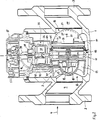
- a composite water meter is shown in longitudinal section. Its housing 1 has an inlet flange 2 and one Outlet flange 3 for connection to a pipeline. The flow direction through the housing 1 is indicated by an arrow 4.
- the housing 1 has an upper opening 5 through a lid 6 is closed.
- Hangs on this cover 6 Main meter measuring insert 7, the measuring chamber 8 in alignment with the water guide channels 9, 10 of the housing 1.
- the water channels 9, 10 are through an outside on the wall of the measuring room 8 circumferential double lip seal 46 waterproof from each other Cut.
- This double-lip seal 46 is pressed when Insert the main meter measuring insert 7 in the housing 1 tight on its inner wall.
- the seal 46 and its arrangement, for example in the middle of the main counter measuring insert 7 is opposite State of the art new.
- This version has the advantage that the inner wall of the housing 1 corresponding to the seal 46 does not have to be machined as a sealing surface.
- the switching valve insert 14 is waterproof with the Main meter measuring insert 7 connected and forms one with this Unit. In the switching valve insert 14 is not to the state of the Technology-related changeover valve 18 arranged, its structure and function is therefore described in detail below.
- the changeover valve insert 14 consists of a housing 19 with a circular flow cross-section, in which a valve seat 20 (Fig. 4, 5) is formed. Furthermore, the diameter of the Housing 19 a pivot axis 21 mounted on the two wings 22, 23 are articulated as closure members of the switching valve 18. For this purpose, the wings 22, 23 with eyes 22.1, 22.2 and 23.1, 23.2 provided, which are penetrated by the pivot axis 21. Like on 3, the pivot axis 21 lies between eyes 22.1, 23.2 and 23.1, 22.2 free. Is in this area a prestressed spiral spring 24 is arranged on the pivot axis 21, whose spring ends 24.1, 24.2 rest on the wings 22, 23 and apply it in the closing direction.
- the wings 22, 23 are therefore at low flows, at which the main meter should not be released, on the valve seat 20 as 4 emerges.
- a flat seal 25 is arranged, which at closed wings 22, 23 between these and the valve seat 20 is pinched.
- the flat seal 25 is form-fitting on the wings 22, 23 fixed, which has knobs 26, 27 (Fig. 4 and Fig. 5). In the area of these knobs 26, 27, the flat seal 25 is included Elongated holes 28, 29 provided, which are on an imaginary line Extend perpendicular to the pivot axis 21. To attach the Flat gasket 25, the elongated holes 28, 29 are somewhat transverse to it Stretched longitudinally so that it extends over the wider heads of the Knobs 26, 27 fit behind which the flat gasket 25 according to her Pass "clicks".
- the impeller 11 is direct on its downstream side stored on the switching valve insert 14.
- the overall length of the unit Master counter measuring insert 7 and changeover valve insert 14 reduced itself and especially the small space requires the changeover valve 18 significantly compared to the prior art.
- the hub 12 In the hub 12 is a known electronic scanning device 15 arranged with the electrical conductor 16 with an electronic counter placed on the housing cover 6 17 is connected.
- the scanner 15 and the electronic Counter 17 belong to the prior art, on the hereby Reference is made so that there is further explanation of these Spare parts.
- the cartridge 36 of the stroke counter 35 is inside a cylindrical one Boundary wall 40 of the main counter measuring insert 7 arranged, the top waterproof with the lid 6 and the bottom waterproof is connected to the wall 41 of the measuring space 8.
- In the Wall 40 and in cartridge 36 are inlet openings 42, 43 or outlet openings 44, 45 for the water flow through the secondary meter intended.
- the changeover valve 18 is closed below the limit flow and the entire amount of water flows through the area above the main meter measuring room 8. It flows through the opening 42 in the wall 40 and the inlet opening 43 in the wall of the Cartridge 36 to the impeller 37 and then flows through the openings 44 in the cartridge 36 and 45 in the wall 40 in the direction Counter output.
- the changeover valve is above the limit flow 18 opened and the greater part of the amount of water flows through the measuring room 8, while a smaller part again the above described way on the secondary counter 35 takes.
- Fig. 2 is another embodiment of a compound water meter shown.
- the hanging on the housing cover 6 Assembly consisting of the main counter measuring insert 7 with integrated Sub-counter 35 and the switching valve insert 14 is in Structure and function completely identical to that of the previous one Embodiment.
- This assembly can be integrated into the Housing 1 inserted or removed from this. It forms an independent unit that is calibrated for itself or can be certified and practically trained in any Housing can be used.
- the only difference to the compound water meter of the first Embodiment is that the middle part of the housing pulled down to the lower edge of inlet flange 2 and outlet flange 3 is.
- This training has the main advantage that the overall height of the compound water meter is significantly reduced, what when comparing the representations according to FIG. 1 and 2 becomes very apparent. But this also results in a oblique course of the water channels 9 and 10 to the measuring room 8 there or away from it.
- This flow through the housing 1 results in higher flow compared to straight flow Pressure drops, which can be coped with, however, because of the changeover valve 18 caused only slight pressure drops. With Conventional changeover valves would be such a flow guide not possible due to space and pressure loss reasons.
Landscapes
- Physics & Mathematics (AREA)
- Fluid Mechanics (AREA)
- General Physics & Mathematics (AREA)
- Measuring Volume Flow (AREA)
Applications Claiming Priority (2)
| Application Number | Priority Date | Filing Date | Title |
|---|---|---|---|
| DE19717725A DE19717725A1 (de) | 1997-04-18 | 1997-04-18 | Verbundwasserzähler |
| DE19717725 | 1997-04-18 |
Publications (2)
| Publication Number | Publication Date |
|---|---|
| EP0874226A1 true EP0874226A1 (fr) | 1998-10-28 |
| EP0874226B1 EP0874226B1 (fr) | 2004-11-10 |
Family
ID=7827866
Family Applications (1)
| Application Number | Title | Priority Date | Filing Date |
|---|---|---|---|
| EP98106125A Expired - Lifetime EP0874226B1 (fr) | 1997-04-18 | 1998-04-03 | Compteur d'eau composé |
Country Status (7)
| Country | Link |
|---|---|
| US (1) | US6079263A (fr) |
| EP (1) | EP0874226B1 (fr) |
| CN (1) | CN1145785C (fr) |
| DE (2) | DE19717725A1 (fr) |
| EA (1) | EA000608B1 (fr) |
| IL (1) | IL124106A (fr) |
| PL (1) | PL186165B1 (fr) |
Cited By (1)
| Publication number | Priority date | Publication date | Assignee | Title |
|---|---|---|---|---|
| WO2007028567A3 (fr) * | 2005-09-08 | 2007-05-10 | M & Fc Holding Llc | Compteur de turbine |
Families Citing this family (20)
| Publication number | Priority date | Publication date | Assignee | Title |
|---|---|---|---|---|
| US6819292B2 (en) | 2001-03-09 | 2004-11-16 | Arad Measuring Technologies Ltd | Meter register |
| US7775422B2 (en) | 2003-06-13 | 2010-08-17 | Arad Measuring Technologies Ltd. | Meter register and remote meter reader utilizing a stepper motor |
| US7267014B2 (en) * | 2004-09-23 | 2007-09-11 | Arad Measuring Technologies Ltd. | Meter register having an encoder |
| US20080110279A1 (en) * | 2005-01-10 | 2008-05-15 | Waitek Limited | Energy/Water Usage Monitor |
| US7412882B2 (en) * | 2006-02-14 | 2008-08-19 | Badger Meter, Inc. | Meter with integral register having no visual display of consumption |
| EP2044584A4 (fr) * | 2006-05-04 | 2017-11-22 | Capstone Mobile Technologies, LLC | Systeme et procede pour surveiller et commander a distance un compteur d'eau |
| US20090205400A1 (en) * | 2008-02-16 | 2009-08-20 | Luther Donald Mcpeak | System and method for measuring fluid flow |
| US9506785B2 (en) | 2013-03-15 | 2016-11-29 | Rain Bird Corporation | Remote flow rate measuring |
| FR3031809A1 (fr) * | 2015-01-16 | 2016-07-22 | Sagemcom Energy & Telecom Sas | Compteur a double moyen de comptage |
| DE102015122426B4 (de) | 2015-12-21 | 2023-05-04 | Zenner International Gmbh & Co. Kg | Verbundwasserzähler |
| CN105784014A (zh) * | 2016-03-14 | 2016-07-20 | 天津银宝山新科技有限公司 | 注塑法兰型磁电式水表 |
| WO2018013857A1 (fr) | 2016-07-13 | 2018-01-18 | Rain Bird Corporation | Capteur d'écoulement |
| CN106768122B (zh) * | 2017-01-23 | 2023-12-05 | 福州真兰水表有限公司 | 一体机芯复式水表 |
| US10473494B2 (en) | 2017-10-24 | 2019-11-12 | Rain Bird Corporation | Flow sensor |
| US11662242B2 (en) | 2018-12-31 | 2023-05-30 | Rain Bird Corporation | Flow sensor gauge |
| CN110530444B (zh) * | 2019-08-30 | 2024-05-28 | 三川智慧科技股份有限公司 | 一种干式无磁nb-iot水表 |
| US11874149B2 (en) | 2020-04-27 | 2024-01-16 | Rain Bird Corporation | Irrigation flow sensor systems and methods of detecting irrigation flow |
| CN112082612A (zh) * | 2020-08-28 | 2020-12-15 | 王红伍 | 一种旋转活塞容积式水表 |
| CN115307691B (zh) * | 2022-08-24 | 2025-08-26 | 宁波水表(集团)股份有限公司 | 流量计量机构及容积式水表 |
| US12443208B2 (en) | 2023-02-08 | 2025-10-14 | Rain Bird Corporation | Control zone devices, systems and methods |
Citations (3)
| Publication number | Priority date | Publication date | Assignee | Title |
|---|---|---|---|---|
| WO1981003700A1 (fr) * | 1980-06-13 | 1981-12-24 | D Kullmann | Debitmetre a liquide composite |
| DE3429007A1 (de) * | 1984-08-07 | 1986-02-13 | Bopp & Reuther Gmbh, 6800 Mannheim | Verbundwasserzaehler |
| EP0718603A2 (fr) * | 1994-12-22 | 1996-06-26 | H. Meinecke Ag | Débitmètre à turbine |
Family Cites Families (15)
| Publication number | Priority date | Publication date | Assignee | Title |
|---|---|---|---|---|
| US3203238A (en) * | 1962-02-12 | 1965-08-31 | Rockwell Mfg Co | Compound meter |
| DE1498396A1 (de) * | 1965-09-22 | 1969-04-24 | Josef Marx | Ventil-Umschaltvorrichtung fuer Verbund-Zaehler |
| US3395578A (en) * | 1965-09-28 | 1968-08-06 | Badger Meter Mfg Co | Compound meter and valve |
| US3707872A (en) * | 1971-05-10 | 1973-01-02 | Gamon Calmet Ind Inc | Compound fluid meter |
| DE2603694A1 (de) * | 1976-01-31 | 1977-08-04 | Rombach Johann Baptist | Elektronisches zaehlgeraet |
| US4175434A (en) * | 1976-12-01 | 1979-11-27 | Badger Meter Inc. | Compound meter assembly |
| US4217929A (en) * | 1976-12-01 | 1980-08-19 | Badger Meter, Inc. | Flow control composite valve |
| US4100800A (en) * | 1976-12-01 | 1978-07-18 | Badger Meter, Inc. | Flow control assemblies |
| DE3732703A1 (de) * | 1987-02-19 | 1988-09-01 | Spanner Pollux Gmbh | Verbundwasserzaehler |
| DE3740531A1 (de) * | 1987-11-30 | 1989-06-08 | Spanner Pollux Gmbh | Verbundwasserzaehler mit einem teilstromzaehler als hauptzaehler |
| DE3924147A1 (de) * | 1989-07-21 | 1991-01-31 | Meinecke Ag H | Verbundwasserzaehler |
| RU2062992C1 (ru) * | 1993-04-07 | 1996-06-27 | Эдуард Сергеевич Мануков | Турбинный расходомер потока жидкости (газа) |
| IL107848A0 (en) * | 1993-12-02 | 1994-04-12 | Paz Ilan | Electronic flowmeter system with a stopper against undesirable flows, leak detector and bypass for measuring low flows |
| IL114155A (en) * | 1995-06-15 | 1998-07-15 | Arad Ltd | Fire service compound meter |
| DE19616330C1 (de) * | 1996-04-24 | 1997-04-10 | Hydrometer Gmbh | Verbundwasserzähler |
-
1997
- 1997-04-18 DE DE19717725A patent/DE19717725A1/de not_active Ceased
-
1998
- 1998-04-03 DE DE59812234T patent/DE59812234D1/de not_active Expired - Lifetime
- 1998-04-03 EP EP98106125A patent/EP0874226B1/fr not_active Expired - Lifetime
- 1998-04-15 IL IL12410698A patent/IL124106A/xx not_active IP Right Cessation
- 1998-04-17 PL PL98325857A patent/PL186165B1/pl not_active IP Right Cessation
- 1998-04-17 US US09/062,454 patent/US6079263A/en not_active Expired - Lifetime
- 1998-04-17 CN CNB981092586A patent/CN1145785C/zh not_active Expired - Fee Related
- 1998-04-17 EA EA199800312A patent/EA000608B1/ru not_active IP Right Cessation
Patent Citations (3)
| Publication number | Priority date | Publication date | Assignee | Title |
|---|---|---|---|---|
| WO1981003700A1 (fr) * | 1980-06-13 | 1981-12-24 | D Kullmann | Debitmetre a liquide composite |
| DE3429007A1 (de) * | 1984-08-07 | 1986-02-13 | Bopp & Reuther Gmbh, 6800 Mannheim | Verbundwasserzaehler |
| EP0718603A2 (fr) * | 1994-12-22 | 1996-06-26 | H. Meinecke Ag | Débitmètre à turbine |
Cited By (2)
| Publication number | Priority date | Publication date | Assignee | Title |
|---|---|---|---|---|
| WO2007028567A3 (fr) * | 2005-09-08 | 2007-05-10 | M & Fc Holding Llc | Compteur de turbine |
| US7650801B2 (en) | 2005-09-08 | 2010-01-26 | M & Fc Holding Llc | Turbine flowmeter |
Also Published As
| Publication number | Publication date |
|---|---|
| PL186165B1 (pl) | 2003-11-28 |
| IL124106A (en) | 2001-08-26 |
| EA199800312A1 (ru) | 1998-10-29 |
| DE19717725A1 (de) | 1998-10-22 |
| PL325857A1 (en) | 1998-10-26 |
| DE59812234D1 (de) | 2004-12-16 |
| EP0874226B1 (fr) | 2004-11-10 |
| CN1145785C (zh) | 2004-04-14 |
| US6079263A (en) | 2000-06-27 |
| EA000608B1 (ru) | 1999-12-29 |
| CN1203357A (zh) | 1998-12-30 |
Similar Documents
| Publication | Publication Date | Title |
|---|---|---|
| EP0874226B1 (fr) | Compteur d'eau composé | |
| EP0271765B1 (fr) | Soupape commandée par le fluide propre, déclenchable notamment par un électroaimant pilote | |
| DE102008003177A1 (de) | Abgasrückführventil für ein Kraftfahrzeug | |
| DE3012059A1 (de) | Pneumatische drosselvorrichtung | |
| DE2744917C3 (de) | Sitzventil mit geradem Durchgang | |
| EP3259506A1 (fr) | Soupape pour réguler le flux d'eau dans une conduite sanitaire | |
| DE2647297C3 (de) | Flügelradzahler | |
| DE3732703C2 (fr) | ||
| EP0305821B1 (fr) | Dispositif pour fermer l'embranchement d'un tube | |
| DE1919383C3 (de) | Drosselklappenventil | |
| DE19717726C1 (de) | Verbundwasserzähler | |
| DE4030611A1 (de) | Absperrorgan | |
| DE2844142C2 (de) | Durchfluß-Steuerventil | |
| WO1983000260A1 (fr) | Installation de remplissage automatique de cellules de batterie | |
| EP0821221B1 (fr) | Compteur d'eau composé | |
| DE102005052385B4 (de) | Druckminderer | |
| EP0407948B2 (fr) | Compteur de liquide à turbine pour mesurer un débit | |
| DE202020102595U1 (de) | Fluidsystem | |
| DE4412683C2 (de) | Verbundwasserzähler | |
| EP1622694B1 (fr) | Indicateur de fuite concu pour un element de filtrage d'un filtre-presse | |
| DE8524288U1 (de) | Membran-Absperrventil für Unterdruck-Abwasserleitungen | |
| DE3331082A1 (de) | Reinigungsrohr mit rueckstauverschluss | |
| DE2506951A1 (de) | Absperrorgan | |
| DE29518733U1 (de) | Druckhalteventil für Kraftstoffanlagen | |
| DE4232774A1 (de) | Verbundwasserzähler |
Legal Events
| Date | Code | Title | Description |
|---|---|---|---|
| PUAI | Public reference made under article 153(3) epc to a published international application that has entered the european phase |
Free format text: ORIGINAL CODE: 0009012 |
|
| AK | Designated contracting states |
Kind code of ref document: A1 Designated state(s): DE FR GB IT |
|
| AX | Request for extension of the european patent |
Free format text: AL;LT;LV;MK;RO;SI |
|
| 17P | Request for examination filed |
Effective date: 19980929 |
|
| AKX | Designation fees paid |
Free format text: DE FR GB IT |
|
| GRAP | Despatch of communication of intention to grant a patent |
Free format text: ORIGINAL CODE: EPIDOSNIGR1 |
|
| RAP1 | Party data changed (applicant data changed or rights of an application transferred) |
Owner name: SENSUS METERING SYSTEMS GMBH HANNOVER |
|
| GRAS | Grant fee paid |
Free format text: ORIGINAL CODE: EPIDOSNIGR3 |
|
| GRAA | (expected) grant |
Free format text: ORIGINAL CODE: 0009210 |
|
| AK | Designated contracting states |
Kind code of ref document: B1 Designated state(s): DE FR GB IT |
|
| REG | Reference to a national code |
Ref country code: GB Ref legal event code: FG4D Free format text: NOT ENGLISH |
|
| REF | Corresponds to: |
Ref document number: 59812234 Country of ref document: DE Date of ref document: 20041216 Kind code of ref document: P |
|
| GBT | Gb: translation of ep patent filed (gb section 77(6)(a)/1977) |
Effective date: 20041215 |
|
| ET | Fr: translation filed | ||
| PLBE | No opposition filed within time limit |
Free format text: ORIGINAL CODE: 0009261 |
|
| STAA | Information on the status of an ep patent application or granted ep patent |
Free format text: STATUS: NO OPPOSITION FILED WITHIN TIME LIMIT |
|
| 26N | No opposition filed |
Effective date: 20050811 |
|
| PG25 | Lapsed in a contracting state [announced via postgrant information from national office to epo] |
Ref country code: IT Free format text: LAPSE BECAUSE OF NON-PAYMENT OF DUE FEES Effective date: 20070403 |
|
| PGRI | Patent reinstated in contracting state [announced from national office to epo] |
Ref country code: IT Effective date: 20110616 |
|
| PGFP | Annual fee paid to national office [announced via postgrant information from national office to epo] |
Ref country code: DE Payment date: 20130620 Year of fee payment: 16 |
|
| PGFP | Annual fee paid to national office [announced via postgrant information from national office to epo] |
Ref country code: FR Payment date: 20130531 Year of fee payment: 16 Ref country code: IT Payment date: 20130424 Year of fee payment: 16 |
|
| PGFP | Annual fee paid to national office [announced via postgrant information from national office to epo] |
Ref country code: GB Payment date: 20140225 Year of fee payment: 17 |
|
| REG | Reference to a national code |
Ref country code: DE Ref legal event code: R119 Ref document number: 59812234 Country of ref document: DE |
|
| REG | Reference to a national code |
Ref country code: FR Ref legal event code: ST Effective date: 20141231 |
|
| PG25 | Lapsed in a contracting state [announced via postgrant information from national office to epo] |
Ref country code: DE Free format text: LAPSE BECAUSE OF NON-PAYMENT OF DUE FEES Effective date: 20141101 |
|
| REG | Reference to a national code |
Ref country code: DE Ref legal event code: R119 Ref document number: 59812234 Country of ref document: DE Effective date: 20141101 |
|
| PG25 | Lapsed in a contracting state [announced via postgrant information from national office to epo] |
Ref country code: FR Free format text: LAPSE BECAUSE OF NON-PAYMENT OF DUE FEES Effective date: 20140430 |
|
| PG25 | Lapsed in a contracting state [announced via postgrant information from national office to epo] |
Ref country code: IT Free format text: LAPSE BECAUSE OF NON-PAYMENT OF DUE FEES Effective date: 20140403 |
|
| GBPC | Gb: european patent ceased through non-payment of renewal fee |
Effective date: 20150403 |
|
| PG25 | Lapsed in a contracting state [announced via postgrant information from national office to epo] |
Ref country code: GB Free format text: LAPSE BECAUSE OF NON-PAYMENT OF DUE FEES Effective date: 20150403 |