EP0874332A2 - System und Verfahren zur Messung und Überwachung von dreidimensionalen Objekten - Google Patents
System und Verfahren zur Messung und Überwachung von dreidimensionalen Objekten Download PDFInfo
- Publication number
- EP0874332A2 EP0874332A2 EP98303207A EP98303207A EP0874332A2 EP 0874332 A2 EP0874332 A2 EP 0874332A2 EP 98303207 A EP98303207 A EP 98303207A EP 98303207 A EP98303207 A EP 98303207A EP 0874332 A2 EP0874332 A2 EP 0874332A2
- Authority
- EP
- European Patent Office
- Prior art keywords
- projector
- real world
- grid patterns
- computer generated
- image
- Prior art date
- Legal status (The legal status is an assumption and is not a legal conclusion. Google has not performed a legal analysis and makes no representation as to the accuracy of the status listed.)
- Withdrawn
Links
Images


Classifications
-
- G—PHYSICS
- G06—COMPUTING OR CALCULATING; COUNTING
- G06T—IMAGE DATA PROCESSING OR GENERATION, IN GENERAL
- G06T7/00—Image analysis
- G06T7/0002—Inspection of images, e.g. flaw detection
- G06T7/0004—Industrial image inspection
- G06T7/001—Industrial image inspection using an image reference approach
-
- G—PHYSICS
- G06—COMPUTING OR CALCULATING; COUNTING
- G06T—IMAGE DATA PROCESSING OR GENERATION, IN GENERAL
- G06T7/00—Image analysis
- G06T7/60—Analysis of geometric attributes
-
- G—PHYSICS
- G06—COMPUTING OR CALCULATING; COUNTING
- G06T—IMAGE DATA PROCESSING OR GENERATION, IN GENERAL
- G06T2207/00—Indexing scheme for image analysis or image enhancement
- G06T2207/10—Image acquisition modality
- G06T2207/10141—Special mode during image acquisition
- G06T2207/10152—Varying illumination
-
- G—PHYSICS
- G06—COMPUTING OR CALCULATING; COUNTING
- G06T—IMAGE DATA PROCESSING OR GENERATION, IN GENERAL
- G06T2207/00—Indexing scheme for image analysis or image enhancement
- G06T2207/30—Subject of image; Context of image processing
- G06T2207/30108—Industrial image inspection
- G06T2207/30164—Workpiece; Machine component
Definitions
- the present invention relates generally to measuring and monitoring three-dimensional shaped objects and more particularly to measuring and monitoring three-dimensional shaped objects with projections of computer models of the objects.
- Gages and dial indicators are traditional tools that have been used for measuring simple shaped objects. However, the gages and dial indicators are not very useful for measuring complex three-dimensional shaped objects.
- Custom-made templates are one type of tool that have been used for measuring complex three-dimensional shaped objects. The custom made templates measure complex three-dimensional shaped objects by checking the cross-sectional profiles of the objects. A problem with using the custom made templates to measure complex three-dimensional shaped objects is that the templates can be expensive and require a great deal of skill to measure the objects and interpret the results.
- Computer controlled coordinate measuring machines CCMS
- the CCM measures complex three-dimensional shaped objects by measuring the dimensions of the objects.
- the CCM is programmed to probe the objects and record coordinates by using a mechanical probe or a laser distance detector.
- the CCM requires lengthy programming, probing cycles, and setup. These limitations make it prohibitive to use the CCM for measuring and monitoring in-process parts that are mounted on machining, forming, or other process equipment. Any time spent on unloading in-process parts from the process, setting up the CCM for measuring the parts, and reloading the parts back in the process will be an unwieldy interruption of manufacturing work- flow.
- Projection moire systems are one type of tool that have been used to measure and monitor in-process parts.
- This invention has overcome the limitations associated with the traditional contact measuring tools and projection moiré systems by using projections of computer models of the three-dimensional shaped objects.
- Computer models are typically generated in mathematical form by using computer aided design (CAD) data or other digitized forms like three-dimensional computed tomography (CT) image data taken from x-ray or magnetic resonance imaging (MRI) devices.
- CAD computer aided design
- CT computed tomography
- MRI magnetic resonance imaging
- the computer models of the three-dimensional shaped objects are in the form of a plurality of grid patterns.
- An image of the computer model of grid patterns is simultaneously projected from two directions by two projectors onto a real world instance of the object. Any variation between the computer model and the real world instance of the object is highlighted directly on the object by interference patterns of the two projections of the images of the computer model of grid patterns.
- the variation is quantified by counting the number of interference patterns on the real world instance of the object.
- This invention is particularly suited for manufacturing processes such as machining operations and composite lay-up operations, where variations can be quickly detected and corrected without interrupting the work flow.
- This invention is also well suited for surgical procedures, where images of internal organs can be projected directly onto the site of surgery and used as an aid to the doctor performing the surgery.
- a model of the three-dimensional shaped object is generated by a computer.
- the model of the three-dimensional shaped object has a plurality of grid patterns.
- a first projector projects an image of the computer generated model of grid patterns.
- a second projector projects the image of the computer generated model of grid patterns.
- the first projector and the second projector have an overlapping projective space.
- a transforming means transforms the image of the computer generated model of grid patterns to the first projector and the second projector in real time.
- the transforming means transforms the image to the first projector and the second projector by locating individual data points on points to the first projector and the second projector, wherein the image of the computer generated model of grid patterns is projected from the first projector and the second projector onto a real world instance of the object.
- the image of the computer generated model of grid patterns projected from the first projector and the second projector is compared with the real world instance of the object. Any variation between the projected images of the computer generated model of grid patterns on the real world instance is then determined.
- a system for monitoring a three-dimensional shaped object comprising:
- the transforming means may formulate a coordinate transformation between the computer generated model of grid patterns and the real world instance of the object for the images projected by the first projector and the second projector, the transforming means formulating the coordinate transformation by arbitrarily selecting a plurality of data points from the computer generated model of grid patterns and a plurality of corresponding data points located on the real world instance of the object and relating the plurality of data points from the real world instance of the object to the corresponding plurality of data points located on the computer generated model of grid patterns.
- the transforming means may derive a transformation matrix from the co-ordinate transformation and the transformation matrix may rotate, scale, reflect, and shear the computer generated model of grid patterns to the real world instance of the object in physical space.
- the comparing means may determine any variation between the projected image of the computer generated model of grid patterns on the real world instance of the object by locating interference patterns between the image projected from the first projector on the real world instance of the object and the image projected from the second projector on the real world instance of the object .
- Means may be provided for quantifying the variation between the projected image of the computer generated model of grid patterns on the real world instance of the object by determining the number, of interference patterns on the real world instance of the object.
- Means may also be provided for modifying the real world instance of the object until interference patterns between the image projected from the first projector and the image projected from the second projector on the real world instance of the object have been removed.
- a method for monitoring a three-dimensional shaped object comprising the steps of:
- the step of transforming may comprise formulating a coordinate transformation between the computer generated model of grid patterns and the real world instance of the object for the images projected by the first projector and the second projector, wherein formulating the coordinate transformation comprises arbitrarily selecting a plurality of data points from the computer generated model of grid patterns and a plurality of corresponding data points located on the real world instance of the object and relating the plurality of data points from the real world instance of the object to the corresponding plurality of data points located on the computer generated model of grid patterns.
- a transformation matrix may be derived from the coordinate transformation and the transformation matrix may rotate, scale, reflect, and shear the computer generated model of grid patterns to the real world instance of the object in physical space.
- the step of comparing may comprise determining any variation between the projected image of the computer generated model of grid patterns on the real world instance of the object by locating interference patterns between the image projected from the first projector on the real world instance of the object and the image projected from the second projector on the real world instance of the object.
- the variation between the projected image of the computer generated model of grid patterns on the real world instance of the object may be quantified by determining the number of interference patterns on the real world instance of the object.
- the real world instance of the object may be modified until interference patterns between the image projected from the first projector and the image projected from the second projector on the real world instance of the object have been removed.
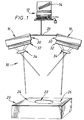
- Fig. 1 is a system 10 for measuring and monitoring three-dimensional shaped objects according to this invention.
- the system includes a computer 12 for generating a computer model 14 of a three-dimensional shaped object.
- the model of the three-dimensional shaped object contains geometric information of the object and is in the form of a plurality of grid patterns.
- the model of grid patterns is based on commercial standard computer-aided design (CAD) data such as IGES files.
- CAD computer-aided design
- the grids are computerized by intersecting the surface of the model with a series of parallel planes.
- the computer transforms the model of grid patterns to a first projector 16 and a second projector 18 having an overlapping projective space.
- An image of the computer model of grid patterns is simultaneously projected from the first projector 16 and the second projector 18 onto a real world instance 20 of the three-dimensional shaped object. If the geometry of a feature 22 (i.e., surfaces, edges, etc.) on the real world instance 20 is the same as the computer model, then the projections from the first projector 16 and the second projector 18 will be coincident with the feature. However, if the projections from the first projector 16 and the second projector 18 are not coincident with the feature 22, then the projections 24 and 26 from the first projector and the second projector, respectively, will interfere with each other and with the feature directly on the real world instance. Areas where the feature 22 is different from the computer model 14 appears as patterns of interference or contours. The difference between the computer model and the feature on the real world instance is quantified by counting the number of patterns of interference.
- Both the first projector 16 and the second projector 18 are connected to the computer 12 through a network 28 and are set up to have an overlapping projective space on the real world instance 20.
- the first projector 16 and the second projector 18 each has a light source 30 for emitting a beam of light, a projection stage 32 for receiving the beam of light and transferring an image of the model of grid patterns from the computer 12 to the real world instance 20, and optical means 34 (i.e. a series of optical devices such as lenses and mirrors) for directing the image of the computer model of grid patterns to the feature 22 on the instance.
- Each projector may include a grid screen for projecting a model with grid patterns if the computer generated model does not have grids.
- the projectors may be a computer controlled laser scanner or an optical device like an overhead projector. If a computer controlled laser scanner is used, then the projection stage 30 may be a light crystal diode (LCD) panel. If an overhead projector is used, then the projection stage may be a flat transparent slide.
- This invention is not limited to a computer controlled laser scanner and other computer controlled devices like a light emitting diode (LED) panel, a cathode ray tube (CRT), an opaque projector, or a photographic slide holder may be used.
- this invention is not limited to an overhead projector, and other optical devices like a slide projector may be used. Regardless of which optical device is used, a graphical hardcopy of the model of grid patterns is produced using a printer or plotter and used as a transparency.
- the real world instance 20 does not require any special setup or position registering with the computer generated model of grid patterns 14.
- the computer generated model of grid patterns 14 and the real world instance are linked by a spatial transform formulated in real time by the computer 12.
- a spatial transform formulated in real time by the computer 12.
- individual data points located on the model of grid patterns are mapped to the first projector 16 and the second projector 18 so that the image of the model of grid patterns is projected from both projectors onto a feature of the real world instance 20.
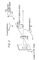
- the spatial transformation uses a unified coordinate system as shown in Fig. 2.
- a transformation T is taken between a model space X m , a real world instance space X o , and an image space X i for each of the projection stages in the first projector and the second projector.
- the unified coordinate system uses Cartesian coordinates of a point (x,y,z) that are represented by (xw, yw, zw, w), wherein w is a scalar factor.
- the transformation T for each projection includes the transformation T 1 from the model space X m to the real world instance space X o and the transformation T 2 from the real world instance space X o to the image on the projection stage X i .
- the transformation T rotates, scales, reflects, and shears the computer model of grid patterns to the real world instance in the real world instance space using the coordinates formulated for the transformation T 1 and the transformation T 2 .
- the coordinates formulated for transformation T 1 and transformation T 2 are represented by equations 1-4 set forth below.
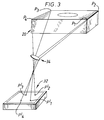
- the unknown variables are solved by arbitrarily selecting four sets of points P 1 , P 2 , P 3 , P 4 on the real world instance 20 and four corresponding sets of points in the model of grid patterns.
- the four points on the real world instance are traced back to their corresponding points P' 1 , P' 2 , P' 3 , and P' 4 in the image of the model of grid patterns on each projection stage in both the first projector and the second projector, as shown in Fig. 3.
- any points in the computer model of grid patterns can be transformed to their image location on the projection stages of both the first projector 16 and the second projector 18. More specifically, by using the computer 12, each point in the computer model of grid patterns is multiplied by the transformation T , transforming an image of the model to the real world instance in real time.
- the transformation matrix eliminates the time consuming steps of precisely aligning and setting up the location of individual model features or other geometric image characteristics that are located in the model of grid patterns as is necessary for conventional systems.
- the system 10 is set up by placing the real world instance 20 within the operating range of the dual projectors. If necessary the optical means 34 in both the first projector 16 and the second projector 18 are adjusted so that the real world instance is positioned within the depth of field of the projection from the dual projectors. In particular, four points (P 1 , P 2 , P 3 , P 4 ) on the real world instance are selected and marked for easy identification. Using optical reciprocity, the plurality of points are traced back through the optical means to locate their respective image (P' 1 , P' 2 , P' 3 , P' 4 ) on the projection stage of both the first projector 16 and the second projector 18 and used to derive the transformation matrix T .
- Fig. 4 shows a projection of a computer model of grid patterns for a feature of a real world instance such as fan blade from both the first projector and the second projector.
- the projection is in the form of a series of curves generated by slicing the surface of the solid model with a set of parallel, equidistant planes on the real world instance.
- Projection A is the projection of the model of grid patterns from the first projector 16 and projection B is the projection of the model of grid patterns from the second projector 18.
- the projections A and B are based on the same model of grid patterns, the difference that is shown in Fig. 4 is due to the difference in the projecting angles of the first projector 16 and the second projector 18 on the feature 24 of the real world instance 20.
- Fig. 5 shows the light grids of the projections from the first projector 16 and the second projector 18 meeting at the surface of the real world instance 20.
- the interference of the light grids of the projections from the first projector 16 and the second projector 18 indicate how well the computer model of grid patterns matches the surface of the real world instance.
- the areas where the computer model of grid patterns 14 are different than the surface of the real world instance are shown in Fig. 5 as periodic constructive interference patterns 36.
- the periodic constructive patterns of interference appear on the surface of the real world instance in the form of contours.
- the contours are a result of the combination of light gratings projected from the first projector 16 and the second projector on the surface of the real world instance 18.
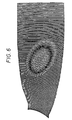
- Fig. 6 shows an example of an image projected on the real world instance having contours.
- the feature of the real world instance is the same as the computer model of grid patterns except at the center of the feature where there are several contour patterns.
- the variation between the model of grid patterns and the real world instance is based on the distance of the real world instance to the computer model of grid patterns. If the projection of the computer model of grid patterns is in the form of a series of curves generated by intersecting the model with a set of parallel, equidistant planes, then the distance between the model and the real world instance can be determined by setting the direction of one of the projectors parallel to the intersection planes.
- the system 10 can be set up such that the angle between the first projector and the second projector, a, is assumed to be constant. Therefore, the variation between the model of grid patterns and the real world instance is quantified by counting the number of interference patterns or contours on the surface of the real world instance.
- the resolution of the system can be adjusted by changing the distance of the parallel plane, ⁇ , or by adjusting the angle between the first projector and the second projector, ⁇ .
- the instance can be modified until the model is equal to the instance or within an acceptable limit.
- the real world instance is modified until the interference patterns between the image projected from the first projector 16 and the second projector 18 have been removed from the surface of the instance.
- the observed variation may be entered into a computer controlled machine which compensates the production variation. It is also possible to correct the machining variation manually until the number of contours projected on the real world instance is within an acceptable limit.
- operator variation or material variation can be quickly modified with this invention, without have to rely on the aforementioned conventional CMM techniques.
- This invention is also suited for various surgical procedures, and can be used to help doctors visualize humans "through-the-skin" as the image of internal organs is recreated and projected on a visible layer of skin or other tissue.
- surgical or other intervening procedures can be planned and performed more precisely and these plans maybe projected directly on the site of the surgery.
- spatial data generated from imaging sources such as a MRI or a CT, can be used directly instead of a computer generated model.
- the grid patterns can be formed by the computer or by using projection screens.
Landscapes
- Engineering & Computer Science (AREA)
- Physics & Mathematics (AREA)
- Computer Vision & Pattern Recognition (AREA)
- General Physics & Mathematics (AREA)
- Theoretical Computer Science (AREA)
- Quality & Reliability (AREA)
- Geometry (AREA)
- Length Measuring Devices By Optical Means (AREA)
- Image Processing (AREA)
Applications Claiming Priority (2)
| Application Number | Priority Date | Filing Date | Title |
|---|---|---|---|
| US08/837,884 US5857032A (en) | 1997-04-25 | 1997-04-25 | System and method for measuring and monitoring three-dimensional shaped objects |
| US837884 | 1997-04-25 |
Publications (2)
| Publication Number | Publication Date |
|---|---|
| EP0874332A2 true EP0874332A2 (de) | 1998-10-28 |
| EP0874332A3 EP0874332A3 (de) | 2003-04-23 |
Family
ID=25275705
Family Applications (1)
| Application Number | Title | Priority Date | Filing Date |
|---|---|---|---|
| EP98303207A Withdrawn EP0874332A3 (de) | 1997-04-25 | 1998-04-24 | System und Verfahren zur Messung und Überwachung von dreidimensionalen Objekten |
Country Status (3)
| Country | Link |
|---|---|
| US (1) | US5857032A (de) |
| EP (1) | EP0874332A3 (de) |
| JP (1) | JP4137225B2 (de) |
Families Citing this family (18)
| Publication number | Priority date | Publication date | Assignee | Title |
|---|---|---|---|---|
| US6384823B1 (en) * | 1999-01-05 | 2002-05-07 | C. Michael Donoghue | System and method for real-time mapping and transfer of coordinate position data from a virtual computer-aided design workspace to the real workspace |
| US6918095B1 (en) * | 1999-06-10 | 2005-07-12 | Dassault Systemes | Dimension generation filter and analysis |
| DE10044169A1 (de) * | 2000-09-07 | 2002-03-21 | Daimler Chrysler Ag | Verfahren zur zerstörungsfreien Wandstärkenprüfung |
| US6841780B2 (en) * | 2001-01-19 | 2005-01-11 | Honeywell International Inc. | Method and apparatus for detecting objects |
| US7881896B2 (en) | 2002-02-14 | 2011-02-01 | Faro Technologies, Inc. | Portable coordinate measurement machine with integrated line laser scanner |
| US20040059616A1 (en) * | 2002-09-20 | 2004-03-25 | Chih-Kuang Chang | System and method for managing measurement work flow |
| ATE523141T1 (de) * | 2004-02-17 | 2011-09-15 | Philips Electronics Ltd | Verfahren und vorrichtung zur registrierung, verifizierung von und bezugnahme auf körperorgane(n) |
| CA2586560A1 (en) * | 2004-11-05 | 2006-06-01 | The Government Of The United States Of America, As Represented By The Se Cretary, Department Of Health And Human Services | Access system |
| US7751868B2 (en) * | 2004-11-12 | 2010-07-06 | Philips Electronics Ltd | Integrated skin-mounted multifunction device for use in image-guided surgery |
| US7805269B2 (en) * | 2004-11-12 | 2010-09-28 | Philips Electronics Ltd | Device and method for ensuring the accuracy of a tracking device in a volume |
| KR100689707B1 (ko) * | 2004-11-12 | 2007-03-08 | 삼성전자주식회사 | 뱅크 선택신호 제어회로, 이를 포함하는 반도체 메모리 장치 및 뱅크 선택신호 제어방법 |
| US8611983B2 (en) * | 2005-01-18 | 2013-12-17 | Philips Electronics Ltd | Method and apparatus for guiding an instrument to a target in the lung |
| EP1838215B1 (de) * | 2005-01-18 | 2012-08-01 | Philips Electronics LTD | Elektromagnetisch verfolgte k-draht-vorrichtung |
| WO2008045016A2 (en) * | 2005-06-21 | 2008-04-17 | Traxtal Inc. | Device and method for a trackable ultrasound |
| EP1898775B1 (de) * | 2005-06-21 | 2013-02-13 | Philips Electronics LTD | System und gerät für die navigierte therapie und diagnose |
| EP1924197B1 (de) * | 2005-08-24 | 2017-10-11 | Philips Electronics LTD | System für flexible navigierte endoskopie |
| JP5141452B2 (ja) * | 2008-09-05 | 2013-02-13 | 富士通株式会社 | 姿勢計測装置及び姿勢計測方法 |
| EP3488233B1 (de) * | 2016-07-22 | 2021-04-28 | LynX Inspection Inc. | Prüfverfahren für einen hergestellten artikel und system zur durchführung desselben |
Family Cites Families (3)
| Publication number | Priority date | Publication date | Assignee | Title |
|---|---|---|---|---|
| US3837198A (en) * | 1973-04-16 | 1974-09-24 | Bendix Corp | Stereoscopic gage and gaging system |
| US5687305A (en) * | 1994-03-25 | 1997-11-11 | General Electric Company | Projection of images of computer models in three dimensional space |
| US5531520A (en) * | 1994-09-01 | 1996-07-02 | Massachusetts Institute Of Technology | System and method of registration of three-dimensional data sets including anatomical body data |
-
1997
- 1997-04-25 US US08/837,884 patent/US5857032A/en not_active Expired - Lifetime
-
1998
- 1998-04-23 JP JP11259498A patent/JP4137225B2/ja not_active Expired - Lifetime
- 1998-04-24 EP EP98303207A patent/EP0874332A3/de not_active Withdrawn
Also Published As
| Publication number | Publication date |
|---|---|
| JP4137225B2 (ja) | 2008-08-20 |
| US5857032A (en) | 1999-01-05 |
| EP0874332A3 (de) | 2003-04-23 |
| JPH1123238A (ja) | 1999-01-29 |
Similar Documents
| Publication | Publication Date | Title |
|---|---|---|
| US5857032A (en) | System and method for measuring and monitoring three-dimensional shaped objects | |
| EP2277000B1 (de) | Verfahren und computerprogramm zur verbesserung der dimensionalen erfassung eines objekts | |
| JP5346033B2 (ja) | 物体の三次元形状を光学的に測定する方法 | |
| US8520930B2 (en) | Method and computer program for improving the dimensional acquisition of an object | |
| EP1276072B1 (de) | Verfahren und System zur Erstellung eines dentalen Modells mittels Bildgebung | |
| Sansoni et al. | Three-dimensional optical measurements and reverse engineering for automotive applications | |
| Schreiber et al. | Theory and arrangements of self-calibrating whole-body 3-D-measurement systems using fringe projection technique | |
| CN106959078B (zh) | 一种用于三维轮廓测量的轮廓测量方法 | |
| EP2183544B1 (de) | Kontaktlose messvorrichtung und verfahren | |
| JP4402458B2 (ja) | 三次元計測における対応ポイントを決定する方法 | |
| JP6293122B2 (ja) | 歯の状況の測定方法 | |
| JP2005509877A (ja) | コンピュータ視覚システムの較正方法及びそのシステム | |
| Son et al. | Path planning of multi-patched freeform surfaces for laser scanning | |
| US5687305A (en) | Projection of images of computer models in three dimensional space | |
| JP4868382B2 (ja) | 磁気刺激における刺激部位の特定あるいはターゲッティングを行うための装置 | |
| US20070177716A1 (en) | Method for determining the co-ordinates of a workpiece | |
| JP4382430B2 (ja) | 頭部の三次元形状計測システム | |
| WO1983004114A1 (en) | Method and apparatus for performing operations on three-dimensional surfaces | |
| Pham et al. | Reverse engineering–hardware and software | |
| KR100457080B1 (ko) | 영상에 의한 암반사면 절리의 기하학적 특성조사방법 | |
| JPH04237310A (ja) | 3次元自動位置決め方法 | |
| JP4159373B2 (ja) | 写真測量における計測点の対応付け方法及び装置 | |
| Islam | Investigation of 3D Scanning Data Quality | |
| Tang et al. | Overview of intelligent CMM guidance technology | |
| Spencer et al. | 3D computer data capture and imaging applied to the face and jaws |
Legal Events
| Date | Code | Title | Description |
|---|---|---|---|
| PUAI | Public reference made under article 153(3) epc to a published international application that has entered the european phase |
Free format text: ORIGINAL CODE: 0009012 |
|
| AK | Designated contracting states |
Kind code of ref document: A2 Designated state(s): AT BE CH CY DE DK ES FI FR GB GR IE IT LI LU MC NL PT SE |
|
| AX | Request for extension of the european patent |
Free format text: AL;LT;LV;MK;RO;SI |
|
| PUAL | Search report despatched |
Free format text: ORIGINAL CODE: 0009013 |
|
| AK | Designated contracting states |
Designated state(s): AT BE CH CY DE DK ES FI FR GB GR IE IT LI LU MC NL PT SE |
|
| AX | Request for extension of the european patent |
Extension state: AL LT LV MK RO SI |
|
| RIC1 | Information provided on ipc code assigned before grant |
Ipc: 7G 01B 11/24 B Ipc: 7G 06T 7/00 B Ipc: 7G 06T 7/60 A |
|
| 17P | Request for examination filed |
Effective date: 20031023 |
|
| AKX | Designation fees paid |
Designated state(s): DE FR GB IT |
|
| 17Q | First examination report despatched |
Effective date: 20070806 |
|
| STAA | Information on the status of an ep patent application or granted ep patent |
Free format text: STATUS: THE APPLICATION IS DEEMED TO BE WITHDRAWN |
|
| 18D | Application deemed to be withdrawn |
Effective date: 20141101 |