EP0874376A2 - Verfahren zur Herstellung eines oxidsupraleitenden Magnetsystems, ein oxidsupraleitendes Magnetsystem, und Vorrichtung zur Erzeugung eines supraleitenden Magnetfeldes - Google Patents
Verfahren zur Herstellung eines oxidsupraleitenden Magnetsystems, ein oxidsupraleitendes Magnetsystem, und Vorrichtung zur Erzeugung eines supraleitenden Magnetfeldes Download PDFInfo
- Publication number
- EP0874376A2 EP0874376A2 EP98107121A EP98107121A EP0874376A2 EP 0874376 A2 EP0874376 A2 EP 0874376A2 EP 98107121 A EP98107121 A EP 98107121A EP 98107121 A EP98107121 A EP 98107121A EP 0874376 A2 EP0874376 A2 EP 0874376A2
- Authority
- EP
- European Patent Office
- Prior art keywords
- superconducting magnet
- persistent current
- current switch
- oxide superconducting
- superconducting
- Prior art date
- Legal status (The legal status is an assumption and is not a legal conclusion. Google has not performed a legal analysis and makes no representation as to the accuracy of the status listed.)
- Withdrawn
Links
- 238000004519 manufacturing process Methods 0.000 title claims abstract description 22
- 230000002085 persistent effect Effects 0.000 claims abstract description 162
- 238000001816 cooling Methods 0.000 claims abstract description 83
- 239000002887 superconductor Substances 0.000 claims abstract description 63
- 238000010438 heat treatment Methods 0.000 claims abstract description 30
- 238000002844 melting Methods 0.000 claims abstract description 27
- 230000008018 melting Effects 0.000 claims abstract description 27
- 238000010276 construction Methods 0.000 claims abstract description 18
- 238000007711 solidification Methods 0.000 claims abstract description 18
- 230000008023 solidification Effects 0.000 claims abstract description 18
- 239000000463 material Substances 0.000 claims abstract description 11
- 238000000034 method Methods 0.000 claims description 30
- 239000003507 refrigerant Substances 0.000 claims description 29
- 230000001172 regenerating effect Effects 0.000 claims description 23
- 239000010949 copper Substances 0.000 description 141
- 239000007788 liquid Substances 0.000 description 53
- 239000001307 helium Substances 0.000 description 28
- 229910052734 helium Inorganic materials 0.000 description 28
- SWQJXJOGLNCZEY-UHFFFAOYSA-N helium atom Chemical compound [He] SWQJXJOGLNCZEY-UHFFFAOYSA-N 0.000 description 28
- RYGMFSIKBFXOCR-UHFFFAOYSA-N Copper Chemical compound [Cu] RYGMFSIKBFXOCR-UHFFFAOYSA-N 0.000 description 20
- 229910052802 copper Inorganic materials 0.000 description 20
- 229910002480 Cu-O Inorganic materials 0.000 description 16
- 108090000623 proteins and genes Proteins 0.000 description 14
- IJGRMHOSHXDMSA-UHFFFAOYSA-N Atomic nitrogen Chemical compound N#N IJGRMHOSHXDMSA-UHFFFAOYSA-N 0.000 description 13
- 230000000694 effects Effects 0.000 description 13
- 102000004169 proteins and genes Human genes 0.000 description 12
- 229910001316 Ag alloy Inorganic materials 0.000 description 11
- BQCADISMDOOEFD-UHFFFAOYSA-N Silver Chemical compound [Ag] BQCADISMDOOEFD-UHFFFAOYSA-N 0.000 description 10
- 230000000052 comparative effect Effects 0.000 description 10
- 229910052751 metal Inorganic materials 0.000 description 10
- 239000002184 metal Substances 0.000 description 10
- 229910052709 silver Inorganic materials 0.000 description 10
- 239000004332 silver Substances 0.000 description 10
- 238000005481 NMR spectroscopy Methods 0.000 description 9
- PCHJSUWPFVWCPO-UHFFFAOYSA-N gold Chemical compound [Au] PCHJSUWPFVWCPO-UHFFFAOYSA-N 0.000 description 9
- 229910052737 gold Inorganic materials 0.000 description 9
- 239000010931 gold Substances 0.000 description 9
- SWQJXJOGLNCZEY-BJUDXGSMSA-N helium-3 atom Chemical compound [3He] SWQJXJOGLNCZEY-BJUDXGSMSA-N 0.000 description 9
- 238000010586 diagram Methods 0.000 description 8
- 230000008901 benefit Effects 0.000 description 7
- 238000007796 conventional method Methods 0.000 description 7
- 229910052754 neon Inorganic materials 0.000 description 7
- GKAOGPIIYCISHV-UHFFFAOYSA-N neon atom Chemical compound [Ne] GKAOGPIIYCISHV-UHFFFAOYSA-N 0.000 description 7
- 229910000896 Manganin Inorganic materials 0.000 description 6
- 125000004435 hydrogen atom Chemical class [H]* 0.000 description 6
- 229910052757 nitrogen Inorganic materials 0.000 description 6
- 238000013461 design Methods 0.000 description 5
- 239000001257 hydrogen Substances 0.000 description 5
- 229910052739 hydrogen Inorganic materials 0.000 description 5
- 230000000704 physical effect Effects 0.000 description 5
- 230000008569 process Effects 0.000 description 5
- 229910001020 Au alloy Inorganic materials 0.000 description 4
- 239000007789 gas Substances 0.000 description 4
- 239000003353 gold alloy Substances 0.000 description 4
- 239000000126 substance Substances 0.000 description 4
- 239000000919 ceramic Substances 0.000 description 3
- 239000013078 crystal Substances 0.000 description 3
- 238000011161 development Methods 0.000 description 3
- 238000005192 partition Methods 0.000 description 3
- 229910015901 Bi-Sr-Ca-Cu-O Inorganic materials 0.000 description 2
- 229910052692 Dysprosium Inorganic materials 0.000 description 2
- 229910052691 Erbium Inorganic materials 0.000 description 2
- 229910052693 Europium Inorganic materials 0.000 description 2
- 229910052688 Gadolinium Inorganic materials 0.000 description 2
- 229910052689 Holmium Inorganic materials 0.000 description 2
- 229910052765 Lutetium Inorganic materials 0.000 description 2
- 229910052779 Neodymium Inorganic materials 0.000 description 2
- PXHVJJICTQNCMI-UHFFFAOYSA-N Nickel Chemical compound [Ni] PXHVJJICTQNCMI-UHFFFAOYSA-N 0.000 description 2
- 229910052777 Praseodymium Inorganic materials 0.000 description 2
- 229910052772 Samarium Inorganic materials 0.000 description 2
- 229910052771 Terbium Inorganic materials 0.000 description 2
- 229910052775 Thulium Inorganic materials 0.000 description 2
- 229910052769 Ytterbium Inorganic materials 0.000 description 2
- 150000001413 amino acids Chemical class 0.000 description 2
- 238000004458 analytical method Methods 0.000 description 2
- 238000005452 bending Methods 0.000 description 2
- 238000004146 energy storage Methods 0.000 description 2
- 239000003822 epoxy resin Substances 0.000 description 2
- 229910052746 lanthanum Inorganic materials 0.000 description 2
- 238000002595 magnetic resonance imaging Methods 0.000 description 2
- QSHDDOUJBYECFT-UHFFFAOYSA-N mercury Chemical compound [Hg] QSHDDOUJBYECFT-UHFFFAOYSA-N 0.000 description 2
- 229910052753 mercury Inorganic materials 0.000 description 2
- 229920000647 polyepoxide Polymers 0.000 description 2
- 229910052706 scandium Inorganic materials 0.000 description 2
- 238000003860 storage Methods 0.000 description 2
- 238000012546 transfer Methods 0.000 description 2
- 229910052727 yttrium Inorganic materials 0.000 description 2
- 229910014472 Ca—O Inorganic materials 0.000 description 1
- MYMOFIZGZYHOMD-UHFFFAOYSA-N Dioxygen Chemical compound O=O MYMOFIZGZYHOMD-UHFFFAOYSA-N 0.000 description 1
- 208000028782 Hereditary disease Diseases 0.000 description 1
- 241000282414 Homo sapiens Species 0.000 description 1
- 208000026350 Inborn Genetic disease Diseases 0.000 description 1
- FYYHWMGAXLPEAU-UHFFFAOYSA-N Magnesium Chemical compound [Mg] FYYHWMGAXLPEAU-UHFFFAOYSA-N 0.000 description 1
- 208000024556 Mendelian disease Diseases 0.000 description 1
- 206010028980 Neoplasm Diseases 0.000 description 1
- RTAQQCXQSZGOHL-UHFFFAOYSA-N Titanium Chemical compound [Ti] RTAQQCXQSZGOHL-UHFFFAOYSA-N 0.000 description 1
- 238000002441 X-ray diffraction Methods 0.000 description 1
- 239000000654 additive Substances 0.000 description 1
- 230000000996 additive effect Effects 0.000 description 1
- 229910045601 alloy Inorganic materials 0.000 description 1
- 239000000956 alloy Substances 0.000 description 1
- 239000004411 aluminium Substances 0.000 description 1
- 229910052782 aluminium Inorganic materials 0.000 description 1
- XAGFODPZIPBFFR-UHFFFAOYSA-N aluminium Chemical compound [Al] XAGFODPZIPBFFR-UHFFFAOYSA-N 0.000 description 1
- 239000007864 aqueous solution Substances 0.000 description 1
- 125000004429 atom Chemical group 0.000 description 1
- QVGXLLKOCUKJST-UHFFFAOYSA-N atomic oxygen Chemical compound [O] QVGXLLKOCUKJST-UHFFFAOYSA-N 0.000 description 1
- 229920000704 biodegradable plastic Polymers 0.000 description 1
- 229920001222 biopolymer Polymers 0.000 description 1
- 230000015572 biosynthetic process Effects 0.000 description 1
- 201000011510 cancer Diseases 0.000 description 1
- 230000008859 change Effects 0.000 description 1
- 150000001875 compounds Chemical class 0.000 description 1
- 230000007423 decrease Effects 0.000 description 1
- 230000003247 decreasing effect Effects 0.000 description 1
- 238000001514 detection method Methods 0.000 description 1
- 230000006866 deterioration Effects 0.000 description 1
- 229910001873 dinitrogen Inorganic materials 0.000 description 1
- 201000010099 disease Diseases 0.000 description 1
- 208000037265 diseases, disorders, signs and symptoms Diseases 0.000 description 1
- 229940079593 drug Drugs 0.000 description 1
- 239000003814 drug Substances 0.000 description 1
- 230000005611 electricity Effects 0.000 description 1
- 230000007613 environmental effect Effects 0.000 description 1
- 239000000945 filler Substances 0.000 description 1
- 238000002649 immunization Methods 0.000 description 1
- 230000003053 immunization Effects 0.000 description 1
- 230000006872 improvement Effects 0.000 description 1
- 208000015181 infectious disease Diseases 0.000 description 1
- 239000011810 insulating material Substances 0.000 description 1
- 238000009413 insulation Methods 0.000 description 1
- 230000003993 interaction Effects 0.000 description 1
- 230000009545 invasion Effects 0.000 description 1
- 239000011777 magnesium Substances 0.000 description 1
- 229910052749 magnesium Inorganic materials 0.000 description 1
- 230000005415 magnetization Effects 0.000 description 1
- 238000005259 measurement Methods 0.000 description 1
- 230000007246 mechanism Effects 0.000 description 1
- 229910001092 metal group alloy Inorganic materials 0.000 description 1
- 239000007769 metal material Substances 0.000 description 1
- 239000000203 mixture Substances 0.000 description 1
- 229910052759 nickel Inorganic materials 0.000 description 1
- 239000001301 oxygen Substances 0.000 description 1
- 229910052760 oxygen Inorganic materials 0.000 description 1
- 230000001717 pathogenic effect Effects 0.000 description 1
- 238000012545 processing Methods 0.000 description 1
- 230000002787 reinforcement Effects 0.000 description 1
- 230000003014 reinforcing effect Effects 0.000 description 1
- 229910052702 rhenium Inorganic materials 0.000 description 1
- WUAPFZMCVAUBPE-UHFFFAOYSA-N rhenium atom Chemical group [Re] WUAPFZMCVAUBPE-UHFFFAOYSA-N 0.000 description 1
- 230000000630 rising effect Effects 0.000 description 1
- 238000012216 screening Methods 0.000 description 1
- 230000035945 sensitivity Effects 0.000 description 1
- 238000012360 testing method Methods 0.000 description 1
- 239000010936 titanium Substances 0.000 description 1
- 229910052719 titanium Inorganic materials 0.000 description 1
- 230000001988 toxicity Effects 0.000 description 1
- 231100000419 toxicity Toxicity 0.000 description 1
- 238000004804 winding Methods 0.000 description 1
Images


Classifications
-
- H—ELECTRICITY
- H01—ELECTRIC ELEMENTS
- H01F—MAGNETS; INDUCTANCES; TRANSFORMERS; SELECTION OF MATERIALS FOR THEIR MAGNETIC PROPERTIES
- H01F6/00—Superconducting magnets; Superconducting coils
Definitions
- the present invention relates to a method of manufacturing an oxide superconducting magnet system and an oxide superconducting magnet system in which an oxide superconductor which was found recently is applied.
- an oxide superconductor of a conventional technique is known to have the critical temperature and the critical magnetic field higher than those of a metal superconductor. It is known that the oxide superconductor has the remarkable advantage over a metal material from the point of view of the critical magnetic field especially at an extremely low temperature of 20K or lower.
- a strong magnetic field magnet using the property of the oxide superconductor has been being developed.
- a persistent current magnet employing the oxide superconductor which was experimentally manufactured is disclosed in "Japanese Journal of Applied Physics" (JJAP) Vol. 35, (1996), pp. 627 to 629.
- the oxide superconductor is made of ceramics, new problems such as a poor mechanical strength and complicated superconducting joint which do not occur in the metal superconductor were recognized and are an obstacle to practical use. Especially, the latter problem may be an obstacle to store magnetic energy in a persistent current mode which is one of the important factors of the superconductor, so that there is a problem in the manufacture.
- the size of the experimental magnet disclosed in the literature is that of a clenched fist.
- the persistent current is at most 30A and the generated magnetic field is less than 1000 gauss.
- a thermal persistent current switch is used in the literature. It takes a long time of few hundreds seconds for the switching operation and a thermal design such as a method of cooling the system is not fully examined. Consequently, it cannot be said that the magnet is considered as a practical large coil.
- the technique disclosed in the Japanese Patent Application Laid-Open No. 3-104042 is not a technique for cooling the persistent current magnet. A method of cooling a system employing a metal superconductor cannot be used as it is. Further, a method of cooling a persistent current magnet including a thermal persistent current switch using an oxide superconductor has never been reported, so that there is also a problem with respect to the cooling operation.
- the oxide superconducting magnet can be used as a persistent current magnet
- the oxide superconducting magnet is used for, for example, a superconducting magnetic energy storage (SMES), a nuclear magnetic resonance spectrometry (NMR), a magnetic resonance imaging apparatus (MRI) for medical application, a superconducting magnet for physical and chemical analysis and test, and the like.
- SMES superconducting magnetic energy storage
- NMR nuclear magnetic resonance spectrometry
- MRI magnetic resonance imaging apparatus
- a superconducting magnet for physical and chemical analysis and test, and the like.
- validity of a strong magnetic field by a persistent current in the physical properties study using an NMR is naturally necessary for the study of magnetic field dependency of the material and is more important to a fact that the signal intensity is increased by the strong magnetic field.
- Protein is a biopolymer in which a number of amino acids are connected according to "design" drawn in DNA and is very important substance which has the responsibility to various life phenomena such as immunization. Protein displays a function indispensable to the life through the tertiary structure showing how amino acids are folded and have the positional relations.
- the body of a living being has more than one hundred thousands kinds of proteins and each of the proteins has a different tertiary structure. It is considered that the various tertiary structures are obtained by combination of about 1000 kinds of fundamental structures. If the fundamental structures of the proteins can be clarified, the proteins can be easily modified and designed according to an object. For example, the mechanisms of diseases such as cancer, infection, and hereditary disease would be more clarified and remarkable improvement in diagnostic and treatment techniques would be resulted. It is expected that development of medicines is accelerated. For instance, processes for screening substances which suppress toxicity of pathogenic proteins would be largely improved.
- An NMR apparatus employing the persistent current magnet by superconduction obtains information regarding structures of various compounds by using nuclear magnetic resonance occurring in atomic nuclei of certain kinds.
- X-ray crystallographic analysis, an electron microscope, and the like can be used. According to the methods, it is necessary to crystallize the proteins.
- the NMR has an advantage that it can be applied to a sample which is difficult to be crystallized, since measurement can be performed in an aqueous solution and operation for crystallizing the protein is unnecessary.
- the upper limit of a detection frequency of a superconducting NMR apparatus used for clarifying the atom and molecule structures with high precision in the substance and material field and the organic and medical field is 750 MHz (17.6T) by the limit of the generation magnetic field.
- an immersing and cooling method in which liquid helium is introduced from a storage container to a cryostat via a transfer tube, a superconducting coil and a persistent current switch are immersed, and natural convection is used.
- the persistent current switch in such a case, for example, in case of a most general thermal persistent current switch, the operation is performed as follows.
- an object of the invention to provide a method of manufacturing an oxide superconducting magnet system which realizes a cooling system satisfying the function of the persistent current magnet while solving the problem from the viewpoint of manufacture peculiar to the oxide superconductor, and to provide an oxide superconducting magnet system and a superconducting magnetic field generating apparatus manufactured according to the method.
- a method of manufacturing an oxide superconducting magnet system according to the invention achieving the object is characterized in that a superconducting magnet part, a persistent current switch part, and a current lead part for superconductively connecting the superconducting magnet part and the persistent current switch part, which are made of an oxide superconductor and construct an oxide superconducting persistent current magnet are preliminarily formed in predetermined shapes and arrangement, the jointing ends of each of the parts are come into contact with each other by connecting parts, a heat treatment for a partial melting followed by solidification is simultaneously performed to thereby make the parts including the connecting parts superconductive, and after that, a cooling system having a predetermined construction necessary for operating the oxide superconducting persistent current magnet is formed.
- An oxide superconducting magnet system according to the invention achieving the object is manufactured by using the method of manufacturing the oxide superconducting magnet system according to any one of claims 1 to 7. It is also possible to manufacture an oxide superconducting magnet system having a persistent current magnet obtained in a manner such that each of a superconducting magnet part, a persistent current switch part, and a current lead part for superconductively connecting the superconducting magnet part and the persistent current switch part is constructed by an oxide superconducting wire and preliminarily formed in desired arrangement and shapes prior to a partial melting heat treatment for making each of the oxide superconductive wires superconductive, the jointing ends of each of the oxide superconducting wires are come into contact with each other by connecting parts which connect the parts in the above formed state, and after that, a heat treatment for a partial melting followed by solidification is simultaneously performed to make the parts including the connecting parts superconductive.
- a superconducting magnetic field generating apparatus uses the oxide superconducting magnet system according to claim 8 or 9.
- an oxide superconducting magnet system having no distortion in superconductive joint and having excellent cooling performance can be obtained.
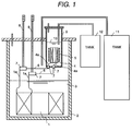
- An oxide superconducting magnet system (hereinbelow, simply called a superconducting magnet system) according to an embodiment of the invention will be described with reference to Fig. 1. That is, a method of manufacturing the superconducting magnet system according to the embodiment of the invention and a method of forming a cooling system structure will be described.
- a superconducting magnet 1 constructed by a superconducting coil is wound with a silver sheathed 55 core tape-shaped wire using a Bi 2 Sr 2 Ca 1 Cu 2 Ox oxide superconductor.
- a thermal persistent current switch 4 is non-inductively wound with a silver-10 weight % gold alloy sheathed 55 core tape-shaped wire using the Bi 2 Sr 2 Ca 1 Cu 2 Ox oxide superconductor.
- Each of current leads 6 for electrically and superconductively connecting the persistent current switch 4 and the superconducting magnet 1 is constructed by a 55 core tape-shaped wire sheathed by a silver alloy containing about 10 weight % of gold by using the Bi 2 Sr 2 Ca 1 Cu 2 Ox oxide superconductor.
- the superconducting magnet part of the embodiment corresponds to the superconducting magnet 1 and the ends 1a
- the persistent current switch part corresponds to the persistent current switch 4
- the current lead part corresponds to the current leads 6.
- the component elements including the connecting parts 7 can be also immersed in an epoxy resin for reinforcement after the heat treatment in accordance with necessity.
- the persistent current circuit is formed by connecting copper current leads 8 connected to an external power source and the connecting parts 7. It is desirable that the copper current leads 8 are detachable.
- the persistent current switch 4 and the heater 5 are insulated from heat by a cryostat 9 as a cryostat for the switch part and are immersed and cooled in liquid helium serving as a refrigerant.
- liquid helium liquid nitrogen, liquid hydrogen, liquid neon, or the like can be used.
- a refrigerant necessary to be supplied to the superconducting magnet part is supplied from a tank 11.
- a refrigerant necessary to cool the persistent current switch part is supplied from a tank 12.
- the refrigerants 3 and 10 are described as liquid helium 3 and 10.
- the cryostat 9 housing the persistent current switch 4 in a heat insulating manner and the superconducting magnet 1 are housed in the cryostat 2 in a heat insulating manner.
- the influence of heat generated by the heater 5 can be avoided by the cryostat 9 and also by controlling a supply amount of the refrigerant 10.
- the oxide superconductor having a low degree of freedom in processing as compared with a metal superconductor, has a problem in assurance of secure superconductive joint and very small distortion. In the embodiment, the following arrangement is used.
- the external dimension and the strength of the connecting parts 7 electrically and superconductively connecting the persistent current switch 4 and the current leads 6 are larger than those of the ends 4a of the persistent current switch 4 and the current leads 6. Consequently, the connecting part 7 is preliminarily arranged so as to be supported (fixed) by a partition wall of the cryostat 9 as a part of the cooling system. With such a construction, even when the cooling system including the cryostat 9 is assembled in order to complete the superconducting magnet system, stress and deformation at the time of the assembly is absorbed by the connecting part 7, so that distortion occurring is reduced.
- connection part 7 which is made superconductive and is reinforced by epoxy resin, filler, or the like is preliminarily arranged in the partition wall of the cryostat 9.
- a construction such that other connecting parts obtained by covering and reinforming the ends 4a of the persistent current switch 4 and the current leads 6 are provided in addition to the connecting part 7 and the other connecting parts are preliminarily arranged on the partition wall of the cryostat 9 can be also used.
- the connecting parts defined in the invention include the connecting parts 7 for superconductive joint and other connecting parts reinformed (or sheathed). It is more preferable that the connecting part is sheathed and reinforced by a heat insulating material.
- Fig. 6 shows a comparative example.
- the comparative example relates to an oxide superconducting magnet system which is produced by using an oxide superconductor and by a method of forming a cooling system of a superconducting persistent current magnet according to a conventional technique.
- the superconducting magnet 1 constructed by the superconducting coil is wound with a silver sheathed 55 core tape-shaped wire using the Bi 2 Sr 2 Ca 1 Cu 2 Ox oxide superconductor.
- the superconducting magnet 1 is housed in the stainless cryostat 2 and is immersed and cooled in the liquid helium 3.
- the thermal persistent current switch 4 is non-inductively wound with the silver-10 weight % metal alloy sheathed 55 core tape-shaped wire using the Bi 2 Sr 2 Ca 1 Cu 2 Ox oxide superconductor, and further, the manganin heater wire 5 is wound on the tape-shaped wire.
- the current leads 6 for superconductively connecting the persistent current switch 4 and the superconducting magnet 1 are constructed by the 55 core tape-shaped wires sheathed by a silver alloy containing about 10 weight % of gold.
- the superconducting magnet 1 and the persistent current switch 4 are superconductively connected via the current leads 6 and the connecting parts 7.
- the persistent current circuit is formed by being connected to an external power source via the copper current leads 8.
- the persistent current switch 4 is housed together with the superconducting magnet 1 in the same cryostat 2 and the persistent current switch 4 is not particularly insulated from heat and is immersed and cooled in the same liquid helium 3.
- the method of manufacturing the oxide superconducting magnet system shown in Fig. 1 will be first described.
- manufacturing performance of the oxide superconductor and cooling performance determined by the physical properties that is, the cooling system construction
- the superconducting magnet part, the persistent current switch part, and the current lead part are butted by wires which are not yet subjected to the partial melting heat treatment and are superconductively jointed by the partial melting heat treatment, thereby realizing the superconductive joint and forming a superconductive closed circuit (that is, the persistent current magnet) by all of the elements.
- the superconducting magnet 1 was immersed and cooled in the liquid helium 3 and the persistent current switch 4 was similarly immersed and cooled in the liquid helium 10, thereby making the superconducting closed circuit superconductive.
- the heater 5 was heated, the temperature of the persistent current switch 4 was increased to 90K in a few minutes, and the superconductive state was shifted to a normal conducting state.
- the amount of heat used was about 20W.
- the liquid helium 10 was evaporated as helium gas by the heating. In such a state, an external power source (not shown) is used, a current of 500A at maximum was supplied from the current lead 8 to the magnet 1 and the magnet was excited to a magnetic field of 15 tesla in about 10 minutes.
- the liquid helium 10 of about 2 liters was injected from the tank 12 of about 2 liters and the persistent current switch 4 was cooled to 4.2K in about 50 seconds and was turned on. After that, the external power source was returned to zero in three minutes and the persistent current mode operation was set.
- a value of resistance of the persistent current switch in a normal conducting state is determined by a value of resistance of the alloy sheath, since a value of inductance varies according to the use and design of various coils, it is difficult to mention an optimum value of resistance. It is desirable that the value of resistance lies within a range about from 1 to few + ohms. It is also desirable that the copper current leads 8 are pulled out to prevent heat invasion via the copper current leads 8 after the mode is shifted to the persistent current mode.
- the superconducting magnet could operate in the persistent current mode in the structure of the first embodiment as mentioned above.
- the temperature of the persistent current switch could not be sufficiently increased.
- the temperature of the persistent current switch was increased only after all of the liquid helium 3 was evaporated to the level at the bottom face of the switch. The time required to increase the temperature was about 50 minutes and the consumed liquid helium 3 reached the amount of 50 litters.
- the external power source was intended to be turned on after confirming that the temperature of the switch increased to 90K. However, since the temperature at the upper end of the coil reached 40K, electricity was turned on only about 20A which is less than about 1/10 of the inherent critical current value A of the coil. The reason can be considered as follows.
- the superconducting magnet was above the liquid level, heat exchange with gas helium was performed, and the temperature increased. After that, liquid helium of 100 liters was injected from the tank 11 for about 20 minutes, the external power source was turned off after the liquid level was returned to the initial state, and the persistent current mode was set. In case of the comparative example, only magnetic field which is less than 1/10 of the case of the first embodiment could be generated.
- the superconducting magnet is installed in the cryostat which houses the superconductive persistent current switch part in a heat insulating manner, thereby forming the cooling system in which the elements can be separately immersed and cooled in the refrigerant. Consequently, the operating speed of the persistent current switch 4 can be increased by more than 10 times as compared with the conventional technique. Further, the consumption of liquid helium at the time of temperature rising and cooling operation can be reduced by one digit, so that it is very effective from the economical point of view. Since the temperature is stabilized, there is also an effect that the magnetic field generated by the superconducting magnet 1 is improved.
- the magnetic field largely exceeding 20T can be generated in the persistent current mode. Consequently, when the invention is applied to an NMR apparatus or the like, a resonance frequency of 1 GHz or higher can be detected, for example, in case of hydrogen atom, so that a remarkable far-reaching effect can be expected in fields such as medical and life science.
- the oxide superconducting magnet system of the invention is characterized in that each of "the superconducting magnet part, the persistent current switch part, and the current lead part for superconductively connecting the superconducting magnet part and the persistent current switch part" is constructed by a tape-shaped oxide superconducting wire which is wound and then subjected to the heat treatment for the partial melting followed by solidification, each part is preliminarily constructed before the heat treatment for the partial melting followed by solidification of the tape wire and is formed in accordance with desired arrangement and shape of a cooling system in which manufacturing performance of the superconducting magnet system is also considered, ends of the tape wires are butted to each other in the connecting parts of the above parts in such a state, and after that, the heat treatment for the partial melting followed by solidification is performed to the whole system to thereby make the system
- all of the parts including the connecting parts are made superconductive and the superconductive closed circuit necessary for the persistent current mode operation can be formed. That is, the partial melting performed after the ends of the wires are butted to each other in the step of producing the superconductive joint system is effective to obtain high crystal orientation in the connecting parts. It is consequently effective to obtain a high critical current density characteristic.
- a cooling system structure indispensable to the superconducting magnet system is added.
- At least the persistent current switch part out of the superconducting magnet part and the persistent current switch part is insulated from heat, thereby holding each part at a desired temperature, enabling the temperature to be adjusted, and efficiently operating the oxide superconducting persistent current magnet.
- the superconducting tape may be deformed a little even after the heat treatment.
- the distortion is within the permissible range when the tape is actually assembled in the product.
- the oxide superconductor is made of ceramics, the dimension is changed by the heat treatment. It can be said that the change of such a degree lies within the permissible range.
- the magnet and the switch it is necessary to thermally insulate the magnet and the switch so that both of them stably operate.
- the persistent current switch part and the superconducting magnet part are housed in the cryostat which are thermally independent and are immersed and cooled by refrigerants, separately.
- refrigerant liquid neon, liquid oxygen, liquid hydrogen, liquid nitrogen, or the like can be properly used according to use.
- the oxide superconducting magnet system for the oxide superconductor (including wire) constructing the superconducting magnet, it is desirable to use silver or a silver alloy, for example, a silver alloy containing a very small amount like 0.01 to 1%, preferably, 0.1 to 0.5% by weight of magnesium, titanium, and nickel as an additive.
- the tensile strength can be increased by more than three times as compared with pure silver. There is accordingly an effect that the superconducting system which withstands electromagnetic force and in which the covering material does not deteriorate by reaction with the oxide superconductor can be constructed.
- a silver sheathed long Bi 2 Sr 2 Ca 1 Cu 2 O8 superconductor having a flat shape in cross section is desirable.
- a multicore wire is more preferable. It is desirable to use a silver alloy containing 1 to 15 weight % of gold for a material covering the persistent current switch and the wire constructing the current lead. By using the silver alloy containing 1 to 15% of gold, the covering material can have high resistance and low heat conductivity. The resistance when the persistent current switch is off can be sufficiently held and the heat conductivity between the switch part kept at a high temperature and the superconducting magnet kept at a low temperature can be avoided. Thus, there is an effect that the superconducting magnet can stably operate.
- the method of manufacturing the oxide superconducting magnet system according to the invention is characterized in that, prior to performing the partial melting followed by solidification the superconducting magnet part, the persistent current switch, and the current lead part of the oxide superconducting persistent current magnet including the superconducting magnet part constructed by the tape-shaped oxide superconductive wire which is wound and then subjected to the heat treatment for the partial melting followed by solidification, the persistent current switch part, and the current lead part for superconductively connecting the superconducting magnet and the persistent current switch part, the parts are preliminarily formed as a system in the desired arrangement and shape, the ends faces of the tape wires are butted to each other in the connecting parts of the above parts, after that, the whole system is subjected to the process of the partial melting followed by solidification, and further, a desired cooling system construction is formed in the superconducting magnet system.
- An oxide superconducting magnet system of a second embodiment according to the invention will be described with reference to Fig. 2.
- the superconducting magnet 1 as a superconducting coil is wound with a silver sheathed 55 core tape-shaped wire using a Bi 2 Sr 2 Ca 1 Cu 2 Ox oxide superconductor.
- the superconducting magnet 1 is inserted into the stainless cryostat 2, laid in a vacuum, and cooled by the regenerative refrigerator 13.
- GM Gifford McMahon
- a refrigerator having three cooling stages can be also used in order to increase the refrigerating ability at a low temperature.
- a pulse pipe refrigerator or the like can be also used.
- the pulse pipe refrigerator has the refrigerating ability lower than that of the GM refrigerator, it has an advantage of no vibration.
- the thermal persistent current switch 4 is non-inductively wound with a silver-10 weight % gold alloy sheathed 55 core tape-shaped wire using the Bi 2 Sr 2 Ca 1 Cu 2 Ox oxide superconductor and the manganin heater wire 5 is further wound around the tape-shaped wire.
- Each of current leads 6 for electrically connecting the persistent current switch 4 and the superconducting magnet 1 is constructed by a 55 core tape-shaped wire sheathed by a silver alloy containing about 10 weight % of gold by using the Bi 2 Sr 2 Ca 1 Cu 2 Ox oxide superconductor.
- the superconducting magnet 1 is heat-conducted or cooled on a second cooling stage 14.
- the superconducting magnet 1 is superconductively jointed to the persistent current switch 4 via the connecting parts 7.
- the persistent current circuit is connected to an external power source via the copper current leads 8.
- a low-temperature end 15 of the copper lead is heat conducted or cooled via the first cooling stage 16 and is connected to the superconducting magnet 1 via a current lead 17 using an oxide superconductor having a small heat conductivity.
- the first cooling stage 16 is also used for cooling a heat shield 18 of a cryostat 2.
- the heat shield 18 is formed in a cup shape of a thin copper and forms a double case with the cryostat 2.
- the heat shield 18 directly houses the superconducting coil 1 and an end of the opening is closely screwed into the first cooling stage 16.
- the copper current leads 8 are detachable.
- the persistent current switch 4 has a construction similar to that of the first embodiment.
- the persistent current switch 4 is heat insulated by a cryostat 9 and is immersed and cooled in liquid helium.
- liquid helium 10 as a refrigerant, liquid nitrogen, liquid hydrogen, liquid neon, or the like can be used.
- Liquid helium necessary to be supplied to the superconducting magnet part is supplied from a tank 11.
- the refrigerant necessary to cool the persistent current switch part is supplied from a tank 12.
- the superconducting magnet 1 was held at 15K by the regenerative refrigerator.
- the persistent current switch was immersed and cooled in liquid helium and was kept at 4.2K.
- the whole circuit was made superconductive.
- an external power source (not shown in the diagram) was used and a current of 300A at maximum was supplied from the copper current leads 8 to the magnet 1, and magnetization was performed to 9 tesla in about 10 minutes.
- two liters of liquid helium was injected from the tank 12, the persistent current switch 4 was cooled to 4.2K in about 50 seconds, and the switch was turned on. After that, the external power source was returned to zero in about three minutes and a persistent current mode operation was set.
- the cooling system is formed in such a manner that the parts constructing the superconductive closed circuit necessary for the persistent current mode operation are simultaneously subjected to heat treatment for a partial melting followed by solidification, after that, the persistent current switch part and the superconducting magnet part are installed in the cryostats which are thermally independent, the persistent current switch part is kept at a desired temperature by the regenerative refrigerator, and the superconducting magnet part is immersed and cooled in the refrigerant.
- the operation of the thermal persistent current switch is facilitated and the consumption of the refrigerants can be reduced.
- FIG. 3 An oxide superconducting magnet system of a third embodiment according to the invention will be described with reference to Fig. 3.
- the structure of the superconducting magnet system of the embodiment is substantially the same as that of the first embodiment, a method of cooling the persistent current switch 4 is different.
- the superconducting magnet 1 as a superconducting coil is wound with a silver sheathed 55 core tape-shaped wire using a Bi 2 Sr 2 Ca 1 Cu 2 Ox oxide superconductor.
- the superconducting magnet 1 is inserted into the stainless cryostat 2 and immersed and cooled in liquid helium 3.
- the thermal persistent current switch 4 is non-inductively wound with a silver-10 weight % gold alloy sheathed 55 core tape-shaped wire using the Bi 2 Sr 2 Ca 1 Cu 2 Ox oxide superconductor and the manganin heater wire 5 is further wound around the tape-shaped wire.
- Each of current leads 6 for electrically connecting the persistent current switch 4 and the superconducting magnet 1 is constructed by a 55 core tape-shaped wire sheathed by a silver alloy containing about 10 weight % of gold by using the Bi 2 Sr 2 Ca 1 Cu 2 Ox oxide superconductor.
- the superconducting magnet 1 and the persistent current switch 4 are superconductively jointed via the current leads 6 and the connecting parts 7.
- the persistent current circuit is connected to an external power source via the copper current leads 8.
- the copper current leads 8 are detachable.
- the persistent current switch 4 is heat insulated by a cryostat 9, heat-conducted or cooled via a second cooling stage 20 by a regenerative refrigerator 19, and is installed in a vacuum.
- a first cooling stage 21 of the refrigerator is used to cool a heat shield 22 of the cryostat 9.
- the heat shield 22 is formed in a cup shape of a thin copper, forms a double case with the cryostat 9, and directly houses the persistent current switch 4. An end of the opening is closely screwed into the cooling stage 21.
- liquid helium necessary to be supplied to the superconducting magnet part is supplied from the tank 11. Instead of liquid helium, liquid nitrogen, liquid hydrogen, liquid neon, or the like can be also used as a refrigerant.
- the superconducting magnet 1 was immersed and cooled in liquid helium.
- the persistent current switch 4 was heat conducted or cooled at about 10K by the regenerative refrigerator. In this state, after the temperature of the switch was increased to 90K in about 100 seconds by the heater 5, an external power source was turned on, and the superconducting magnet was excited to 10T. In such a state, when the temperature of the heater 5 reached about 20K in 10 minutes while cooling the switch 4 by the refrigerator 19, the external power source was turned off and the persistent current mode operation could be set.
- the construction as shown in Fig. 5 which will be shown hereinlater can be also used. With the construction of Fig. 5, it takes only few tens seconds to cool the switch part and there is an advantage that the switching operation is quickly performed.
- the cooling system is formed in such a manner that the parts constructing the superconductive closed circuit necessary for the persistent current mode operation are simultaneously subjected to heat treatment for a partial melting followed by solidification, after that, the superconducted persistent current switch part and the superconducting magnet part are installed in the cryostats which are thermally independent, the persistent current switch part is kept at a desired temperature by the regenerative refrigerator, and the superconducting magnet part is immersed and cooled in the refrigerant.
- the operation of the thermal persistent current switch is facilitated and the consumption of the refrigerants can be reduced.
- An oxide superconducting magnet system of a fourth embodiment according to the invention will be described with reference to Fig. 4.
- the superconducting magnet 1 as a superconducting coil is wound with a silver sheathed 55 core tape-shaped wire using a Bi 2 Sr 2 Ca 1 Cu 2 Ox oxide superconductor.
- the persistent current switch 4 is non-inductively wound with a 55 core tape-shaped wire sheathed by a silver alloy containing about 10 weight % of gold using a Bi 2 Sr 2 Ca 1 Cu 2 Ox oxide superconductor and a manganin heater wire 5 is wound around the tape-shaped wire.
- Each of the current leads 6 electrically connecting the persistent current switch 4 and the superconducting magnet 1 is constructed by a 55 core tape-shaped wire sheathed by a silver alloy containing about 10 weight % of gold using a Bi 2 Sr 2 Ca 1 Cu 2 Ox oxide superconductor.
- the superconducting magnet 1, the persistent current switch 4, and the like are inserted into the stainless cryostat 2, put in a vacuum, heat-insulated from each other, and cooled by regenerative refrigerators 13 and 19.
- a Gifford McMahon (commonly called "GM") refrigerator having two cooling stages is used here as a regenerative refrigerator
- a refrigerator having three cooling stages can be also used in order to increase the refrigerating ability at a low temperature depending on the use.
- a pulse pipe refrigerator or the like can be also used. Although the pulse pipe refrigerator has the refrigerating ability lower than that of the GM refrigerator, it has an advantage of no vibration.
- the superconducting magnet 1 is heat conducted or cooled on a second cooling stage 14 of the regenerative refrigerator 13.
- the superconducting magnet 1 is superconductively jointed to the persistent current switch 4 by the connecting parts 7.
- the persistent current circuit is connected to an external power source via the copper current leads 8.
- Low temperature ends 15 of the copper lead are heat-conducted or cooled via a first cooling stage 16 and are connected to the superconducting magnet 1 via current leads 17 using an oxide superconductor having a small heat conductivity.
- the first cooling stage 16 is also used for cooling a heat shield 18.
- the heat shield 18 is formed in a cup shape of a thin copper.
- the heat shield 18 directly houses the superconducting coil 1, the persistent current switch 4, and the like and an end of the opening is closely screwed into the first cooling stage 16.
- the copper current leads 8 are detachable.
- the persistent current switch 4 is heat insulated or cooled via a second cooling stage 20 by the regenerative refrigerator 19 and is installed in the vacuum heat shield 18.
- the cryostat 2 and the heat shield 18 construct a double case which is preferable to form the heat insulation and vacuum.
- the first cooling stage 21 of the refrigerator 19 is similarly used to cool the heat shield 18. Although there is no cryostat for housing the persistent current switch part in a heat insulating manner, the persistent current switch part has a sufficient distance from the superconducting magnet 1 so that there are effects that the heat conductance is prevented and deterioration in performance by a magnetic field leaked from the magnet can be prevented.
- the connecting parts 7 (including connecting parts for covering and reinforcing the ends 1a of the superconducting magnet 1 or the current leads 6) are preliminarily supported and fixed to the second cooling stage 14 as a part of the cooling system, thereby reducing distortion occurring at the time of assembly.
- the superconducting magnet 1 and the persistent current switch 4 are put in the same space but are heat-insulated in vacuum and are cooled to 15K by the regenerative refrigerators.
- the heater 5 is heated and increased to 90K in about one minute.
- the superconducting magnet 1 is magnetized to 7T by an external power source. After that, the heater is turned off and the switch part is cooled. After confirming that it reached 20K in about 20 minutes, the external power source is turned off and the persistent current mode operation is set.
- the cooling system is formed in such a manner that the parts constructing the superconductive closed circuit necessary for the persistent current mode operation are simultaneously subjected to heat treatment for a partial melting followed by solidification, after that, the persistent current switch part and the superconducting magnet part are installed in the cryostats which are thermally independent, and the persistent current switch part and the superconducting magnet part are held at desired temperatures by the regenerative refrigerator.
- the operation of the system is facilitated and the consumption of the refrigerants can be reduced.
- the persistent current switch part and the superconducting magnet part are installed in cryostats which are thermally independent and the temperature of the superconducting magnet part is held to a desired temperature, for example, to 20K by the regenerative refrigerator, thereby increasing the operating speed of the persistent current switch, facilitating the operation of the magnet system, and reducing the amount of refrigerant consumed by the system.
- a superconducting magnet system of a fifth embodiment according to the invention will be described with reference to Fig. 5.
- a cooling accelerating means is added to the method of cooling the persistent current switch 4.
- the superconducting magnet 1 as a superconducting coil is wound with a silver sheathed 19 core tape-shaped wire using a Bi 2 Sr 2 Ca 1 Cu 2 Ox oxide superconductor.
- the superconducting magnet 1 is inserted into the stainless cryostat 2 and immersed and cooled in liquid helium 3.
- the thermal persistent current switch 4 is non-inductively wound with a silver-10 weight % gold alloy sheathed 19 core tape-shaped wire using a Bi 2 Sr 2 Ca 1 Cu 2 Ox oxide superconductor and the manganin heater wire 5 is further wound around the tape-shaped wire.
- a 55 core tape-shaped wire sheathed by a silver alloy containing about 10 weight % of gold by using the Bi 2 Sr 2 Ca 1 Cu 2 Ox oxide superconductor is used as each of current leads 6 for electrically connecting the persistent current switch and the superconducting magnet and are superconductively jointed to the superconducting magnet 1 and the persistent current switch 4 in the connecting parts 7.
- the persistent current circuit is connected to an external power source via the copper current leads 8.
- the copper current leads 8 are detachable.
- the persistent current switch 4 is heat insulated by a cryostat 9, heat conducted or cooled via a second cooling stage 20 by a regenerative refrigerator 19, and is installed in a vacuum.
- a first cooling stage 20 of the regenerative refrigerator 19 is used to cool a heat shield 22.
- the heat shield 22 is formed thinly of aluminium, directly houses the persistent current switch 4, and an end of the opening is closely attached to the cooling stage 21.
- liquid helium necessary to be supplied to the superconducting magnet part is supplied from the tank 11. Instead of liquid helium, liquid nitrogen, liquid hydrogen, liquid neon, or the like can be also used as a refrigerant.
- a refrigerant pipe 23 for forced cooling is arranged in addition to the above construction.
- a refrigerant low-temperature helium gas, liquid helium, liquid nitrogen, low-temperature nitrogen gas, liquid neon, low-temperature neon gas or the like can be used. It is preferable to arrange the refrigerant pipe 23 around the switch when the persistent current switch is small and to arrange the refrigerant pipe 23 in the switch when the persistent current switch is large. It is preferable to use a material having a good heat conductivity such as copper.
- the persistent current switch part includes at least a switch for thermally increasing or decreasing temperature, thereby more finely adjusting the operating speed of the switch.
- an external magnetic field can be also applied to the switch part.
- the oxide superconductor of the embodiment is a long silver sheathed Bi 2 Sr 2 Ca 1 Cu 2 O8 superconductor having a flat shape in cross section. More preferably, it is a multicore wire. There are following Bi-Sr-Ca-Cu-O superconductors.
- the problems from the view point of manufacture such as joint and distortion can be solved and there is an effect that the oxide superconducting magnetic system in which the persistent current mode operation can be stably performed can be provided.
- the magnetic field generating apparatus using the oxide superconducting magnet system of the invention to an analyzing apparatus, a nuclear magnetic resonance spectrometry apparatus, a strong magnetic field generating apparatus, a magnetic separating apparatus, a superconducting magnetic energy storage, and the like, a practically useful system can be built and there is also an effect that the invention widely contributes to the society.
Landscapes
- Engineering & Computer Science (AREA)
- Power Engineering (AREA)
- Containers, Films, And Cooling For Superconductive Devices (AREA)
- Superconductors And Manufacturing Methods Therefor (AREA)
Applications Claiming Priority (3)
| Application Number | Priority Date | Filing Date | Title |
|---|---|---|---|
| JP10464397A JPH10294213A (ja) | 1997-04-22 | 1997-04-22 | 酸化物系超電導マグネットシステムの製造方法及び酸化物系超電導マグネットシステム及び超電導磁場発生装置 |
| JP104643/97 | 1997-04-22 | ||
| JP10464397 | 1997-04-22 |
Publications (2)
| Publication Number | Publication Date |
|---|---|
| EP0874376A2 true EP0874376A2 (de) | 1998-10-28 |
| EP0874376A3 EP0874376A3 (de) | 1999-06-16 |
Family
ID=14386143
Family Applications (1)
| Application Number | Title | Priority Date | Filing Date |
|---|---|---|---|
| EP98107121A Withdrawn EP0874376A3 (de) | 1997-04-22 | 1998-04-20 | Verfahren zur Herstellung eines oxidsupraleitenden Magnetsystems, ein oxidsupraleitendes Magnetsystem, und Vorrichtung zur Erzeugung eines supraleitenden Magnetfeldes |
Country Status (2)
| Country | Link |
|---|---|
| EP (1) | EP0874376A3 (de) |
| JP (1) | JPH10294213A (de) |
Cited By (6)
| Publication number | Priority date | Publication date | Assignee | Title |
|---|---|---|---|---|
| GB2420910A (en) * | 2004-12-01 | 2006-06-07 | Siemens Ag | Superconducting device having a cryogenic system and a superconducting switch |
| GB2447183B (en) * | 2006-01-06 | 2010-10-27 | Quantum Design Inc | A magnet system, a switch for use with a superconducting magnet and a method for generating magnetic fields |
| DE102011013577A1 (de) * | 2011-03-10 | 2012-09-13 | Karlsruher Institut für Technologie | Vorrichtung zur Speicherung von Wasserstoff und von magnetischer Energie sowie ein Verfahren zu ihrem Betrieb |
| GB2496287A (en) * | 2011-10-31 | 2013-05-08 | Gen Electric | Systems and methods for alternatingly switching a persistent current switch between a normal mode and a superconducting mode |
| US9704630B2 (en) | 2014-10-23 | 2017-07-11 | Hitachi, Ltd. | Superconducting magnet, MRI apparatus and NMR apparatus |
| CN110581381A (zh) * | 2018-06-07 | 2019-12-17 | 东芝三菱电机产业系统株式会社 | 电气设备内置耐压装置及密闭容器电线贯通部处理方法 |
Families Citing this family (11)
| Publication number | Priority date | Publication date | Assignee | Title |
|---|---|---|---|---|
| JP4095742B2 (ja) * | 1999-09-30 | 2008-06-04 | 株式会社神戸製鋼所 | 伝導冷却型超電導マグネット |
| JP4562947B2 (ja) * | 2001-05-15 | 2010-10-13 | 富士電機ホールディングス株式会社 | 超電導磁石 |
| JP4592498B2 (ja) * | 2005-05-30 | 2010-12-01 | 株式会社東芝 | 永久電流超電導マグネットおよびこのマグネットに使用される永久電流スイッチ |
| DE102005029151B4 (de) * | 2005-06-23 | 2008-08-07 | Bruker Biospin Ag | Kryostatanordnung mit Kryokühler |
| JP4790752B2 (ja) * | 2008-04-28 | 2011-10-12 | 株式会社日立製作所 | 超電導マグネット |
| JP5255425B2 (ja) * | 2008-12-22 | 2013-08-07 | 株式会社日立製作所 | 電磁石装置 |
| JP2010283186A (ja) * | 2009-06-05 | 2010-12-16 | Hitachi Ltd | 冷凍機冷却型超電導磁石 |
| KR101367142B1 (ko) * | 2011-10-12 | 2014-02-26 | 삼성전자주식회사 | 초전도 전자석 장치 |
| JP2013122981A (ja) * | 2011-12-12 | 2013-06-20 | Hitachi Ltd | 超電導マグネット、超電導線材の接続方法 |
| JP2014192490A (ja) * | 2013-03-28 | 2014-10-06 | Kobe Steel Ltd | 永久電流スイッチ及びこれを備える超電導装置 |
| JP2024035738A (ja) * | 2022-09-02 | 2024-03-14 | 株式会社日立製作所 | 超電導磁石装置、及び核磁気共鳴診断装置 |
Family Cites Families (2)
| Publication number | Priority date | Publication date | Assignee | Title |
|---|---|---|---|---|
| JPH04167403A (ja) * | 1990-10-31 | 1992-06-15 | Toshiba Corp | 超電導磁石の製造方法 |
| EP0740314A1 (de) * | 1995-04-27 | 1996-10-30 | Hitachi, Ltd. | Supraleitendes Magnetsystem |
-
1997
- 1997-04-22 JP JP10464397A patent/JPH10294213A/ja active Pending
-
1998
- 1998-04-20 EP EP98107121A patent/EP0874376A3/de not_active Withdrawn
Cited By (14)
| Publication number | Priority date | Publication date | Assignee | Title |
|---|---|---|---|---|
| GB2420910A (en) * | 2004-12-01 | 2006-06-07 | Siemens Ag | Superconducting device having a cryogenic system and a superconducting switch |
| DE102004058006B3 (de) * | 2004-12-01 | 2006-06-08 | Siemens Ag | Supraleitungseinrichtung mit Kryosystem und supraleitendem Schalter |
| US7383688B2 (en) | 2004-12-01 | 2008-06-10 | Siemens Atkiengesellschaft | Superconducting device having a cryogenic system and a superconducting switch |
| GB2420910B (en) * | 2004-12-01 | 2009-01-28 | Siemens Ag | Superconducting device having a cryogenic system and a superconducting switch |
| GB2447183B (en) * | 2006-01-06 | 2010-10-27 | Quantum Design Inc | A magnet system, a switch for use with a superconducting magnet and a method for generating magnetic fields |
| DE102011013577A1 (de) * | 2011-03-10 | 2012-09-13 | Karlsruher Institut für Technologie | Vorrichtung zur Speicherung von Wasserstoff und von magnetischer Energie sowie ein Verfahren zu ihrem Betrieb |
| DE102011013577B4 (de) * | 2011-03-10 | 2013-02-28 | Karlsruher Institut für Technologie | Vorrichtung zur Speicherung von Wasserstoff und von magnetischer Energie sowie ein Verfahren zu ihrem Betrieb |
| GB2496287A (en) * | 2011-10-31 | 2013-05-08 | Gen Electric | Systems and methods for alternatingly switching a persistent current switch between a normal mode and a superconducting mode |
| CN103091653A (zh) * | 2011-10-31 | 2013-05-08 | 通用电气公司 | 用于在第一模式和第二模式之间交替切换持续电流开关的系统和方法 |
| GB2496287B (en) * | 2011-10-31 | 2014-02-26 | Gen Electric | Systems and methods for alternatingly switching a persistent current switch between a first mode and a second mode |
| US8922308B2 (en) | 2011-10-31 | 2014-12-30 | General Electric Company | Systems and methods for alternatingly switching a persistent current switch between a first mode and a second mode |
| US9704630B2 (en) | 2014-10-23 | 2017-07-11 | Hitachi, Ltd. | Superconducting magnet, MRI apparatus and NMR apparatus |
| CN110581381A (zh) * | 2018-06-07 | 2019-12-17 | 东芝三菱电机产业系统株式会社 | 电气设备内置耐压装置及密闭容器电线贯通部处理方法 |
| CN110581381B (zh) * | 2018-06-07 | 2021-08-10 | 东芝三菱电机产业系统株式会社 | 电气设备内置耐压装置及密闭容器电线贯通部处理方法 |
Also Published As
| Publication number | Publication date |
|---|---|
| JPH10294213A (ja) | 1998-11-04 |
| EP0874376A3 (de) | 1999-06-16 |
Similar Documents
| Publication | Publication Date | Title |
|---|---|---|
| EP0874376A2 (de) | Verfahren zur Herstellung eines oxidsupraleitenden Magnetsystems, ein oxidsupraleitendes Magnetsystem, und Vorrichtung zur Erzeugung eines supraleitenden Magnetfeldes | |
| Maeda et al. | The MIRAI program and the new super-high field NMR initiative and its relevance to the development of superconducting joints in Japan | |
| Razeti et al. | Construction and Operation of Cryogen Free ${\hbox {MgB}} _ {2} $ Magnets for Open MRI Systems | |
| US6169402B1 (en) | Nuclear magnetic resonance spectrometer | |
| Bray | Superconductors in applications; some practical aspects | |
| CN102483447B (zh) | 包含超导主磁体、超导梯度场线圈和冷却rf线圈的mri系统 | |
| US7218115B2 (en) | Superconductor probe coil for NMR apparatus | |
| US7985714B2 (en) | Nb3Sn superconducting wire and precursor therefor | |
| EP2353170B1 (de) | Elektromagnet | |
| Takahashi et al. | Detection of 1H NMR signal in a trapped magnetic field of a compact tubular MgB2 superconductor bulk | |
| WO2002059917A1 (en) | Liquid cryogen-free superconducting magnet system | |
| WO2011060699A1 (zh) | 适用于磁共振成像的低温冷却的超导体梯度线圈模块 | |
| GB2267570A (en) | Superconducting MRI magnet using a cryocooler | |
| Morita et al. | 10 T conduction cooled Bi-2212/Ag HTS solenoid magnet system | |
| Hazelton et al. | HTS insert coils for high field NMR spectroscopy | |
| JP3677166B2 (ja) | 高磁場発生用永久電流マグネット装置 | |
| Amaya et al. | Pressure induced superconductivity in some simple systems | |
| WO2025247869A1 (en) | High temperature superconductor (hts)-based connections between magnet coils | |
| Lapa et al. | Detection of electromagnetic phase transitions using a helical cavity susceptometer | |
| Sun et al. | Systematic investigation of a NbTi-Bi2223 hybrid low-resistive joint | |
| Kim et al. | 7 T Niobium-Titanium-Based Persistent-Mode Superconducting Magnet for an Electron Beam Ion Source | |
| CN209691508U (zh) | 电流引线及低温组件 | |
| Wiegers et al. | Compact PrNi5 nuclear demagnetization cryostat | |
| JPH09298320A (ja) | 酸化物超電導コイル用永久電流スイッチおよびそれを用いたスイッチ装置並びにスイッチング方法 | |
| van der Laan et al. | A 1 T, 0.33 m bore superconducting magnet operating with cryocoolers at 12 K (for MRI) |
Legal Events
| Date | Code | Title | Description |
|---|---|---|---|
| PUAI | Public reference made under article 153(3) epc to a published international application that has entered the european phase |
Free format text: ORIGINAL CODE: 0009012 |
|
| AK | Designated contracting states |
Kind code of ref document: A2 Designated state(s): DE FR GB |
|
| AX | Request for extension of the european patent |
Free format text: AL;LT;LV;MK;RO;SI |
|
| PUAL | Search report despatched |
Free format text: ORIGINAL CODE: 0009013 |
|
| AK | Designated contracting states |
Kind code of ref document: A3 Designated state(s): AT BE CH CY DE DK ES FI FR GB GR IE IT LI LU MC NL PT SE |
|
| AX | Request for extension of the european patent |
Free format text: AL;LT;LV;MK;RO;SI |
|
| AKX | Designation fees paid |
Free format text: DE FR GB |
|
| STAA | Information on the status of an ep patent application or granted ep patent |
Free format text: STATUS: THE APPLICATION IS DEEMED TO BE WITHDRAWN |
|
| 18D | Application deemed to be withdrawn |
Effective date: 19991217 |