EP0874479A2 - Appareil de communication optique sans câble - Google Patents
Appareil de communication optique sans câble Download PDFInfo
- Publication number
- EP0874479A2 EP0874479A2 EP98106653A EP98106653A EP0874479A2 EP 0874479 A2 EP0874479 A2 EP 0874479A2 EP 98106653 A EP98106653 A EP 98106653A EP 98106653 A EP98106653 A EP 98106653A EP 0874479 A2 EP0874479 A2 EP 0874479A2
- Authority
- EP
- European Patent Office
- Prior art keywords
- holder
- module
- receiving
- base plate
- laser diode
- Prior art date
- Legal status (The legal status is an assumption and is not a legal conclusion. Google has not performed a legal analysis and makes no representation as to the accuracy of the status listed.)
- Withdrawn
Links
Images







Classifications
-
- H—ELECTRICITY
- H04—ELECTRIC COMMUNICATION TECHNIQUE
- H04B—TRANSMISSION
- H04B10/00—Transmission systems employing electromagnetic waves other than radio-waves, e.g. infrared, visible or ultraviolet light, or employing corpuscular radiation, e.g. quantum communication
- H04B10/11—Arrangements specific to free-space transmission, i.e. transmission through air or vacuum
- H04B10/112—Line-of-sight transmission over an extended range
- H04B10/1123—Bidirectional transmission
- H04B10/1127—Bidirectional transmission using two distinct parallel optical paths
Definitions
- the present invention relates to a device for wireless open space optical transmission.
- the present invention is also intended to provide a device for open space optical transmission, which is also available for a bidirectional transmission only 2 devices required.
- a device for free-space optical transmission is also to be created in which only one transmission link needs to be adjusted.
- These new devices are also said to have low power consumption, For example, 0.5 amperes at 12 V DC and in continuous operation.
- the free-space optical transmission should be by means of a light pulse edge modulation, a light pulse phase modulation, a light pulse frequency modulation or further modulation methods derived from this.
- the essence of the invention is namely a device for open space to create optical information transmission, which is a pulsed laser diode with a wavelength in a transmission window at 904 nm or Has 267 nm.
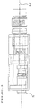
- the device according to the invention for the spatial optical transmission of data, voice, sound and image information comprises at least one transmitter module (2) with a laser diode, an optical transmitter (4), a navigation aid and / or a target device (5) , one or more circuit board (s) and / or one or more hybrid unit (s), one or more adjustment device (s), a connection (6) for the common inlet of current and control pulses, and optionally one or more operating and / or measuring device (s) and / or control signal connections, wherein a longitudinal axis of the receiving module 1 and a longitudinal axis of the transmitting module 2 are arranged parallel to one another and in a plane E 1 , the transmitting module 2 is mounted in a holder 7, which is rigidly connected to a base plate 8 is and the receiving module 1 is mounted in a holder 9 which is rigidly connected to a base plate 8.
- the transmitter module 2 is preferably in a first position Bracket 7 can be moved forwards and backwards and is the receiving module 1 with respect to its position in a second holder 9 forward and backward movable at the rear, with part of the second bracket in its vertical and horizontal position to the base plate 8 is movable.
- the transmitter module 2 within its first holder 7 and / or the receiver module in its second holder 9 and is rotatable about the longitudinal axis in the transmitter module 2 the laser diode and / or in the receiver module 1 the avalanche photodiode contained in a tapered holder.
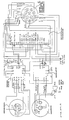
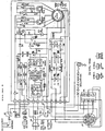
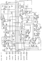
- FIGS. 1-4 Reference is generally made to FIGS. 1-4.
- one or more hybrid units can also be used be provided.
- the cylindrical transmitter module 2 comprises a laser diode for the transmission of optical ones Light pulses. It is essential to the invention that the laser diode either a wavelength in a range between 897 nm and 911 nm, preferred 900 nm - 908 nm, particularly preferably 903 nm - 905 nm, in particular one wavelength of 904 nm, or a wavelength in a range between 260 nm and 274 nm, preferably 263 nm - 271 nm, particularly preferably 266 nm - 268 nm, in particular has a wavelength of 267 nm, and a pulsed operation the laser diode, e.g. B. by means of a pulsed electronic control is. In particular, a light pulse edge modulation, a light pulse phase modulation, a light pulse frequency modulation or other modulation methods derived therefrom.
- the laser diode is preferably mounted in a tapered holder.
- the tapered bracket is preferred because it is the largest possible Number of adjustments possible.
- the transmission module 2 preferably also comprises a multi-stage amplifier unit and the necessary impedance converters. It is preferred to be extreme to use low-noise transistors, for example gallium arsenide transistors.
- the transmitter module 2 also includes sockets for the power and Signal supply and for measuring the transmission signals.
- the cylindrical receiving module 1 comprises a photodiode, in particular one Avalanche photodiode, for receiving optical light pulses. Light impulses of the type mentioned above are preferred.
- the receiving optics is preferred 3 equipped with a light filter, which the bandwidth of the Light frequency spectrum in favor of better use of the preferred Limits light frequency of 904 nm or 267 nm and in particular one Bandpass filter is.
- the photodiode is in turn tapered according to the above information Mounted bracket.
- the laser diode and the avalanche photodiode are preferably adjusted and possibly fixed that the laser diode in the focal point of the transmission optics 4 and the avalanche photodiode is in the focus of the receiving optics 3.
- the receiving module 1 preferably also comprises a low-noise, broadband Video signal amplifier unit and the necessary control loops for optimal Adjustment of the amplifier intensity of the video signal amplifier unit.
- the receiving module 1 also includes sockets for the power and signal supply as well as for measuring the received signals.
- the target device 5 is connected to the base plate 8, movable in its longitudinal axis and arranged between the receiving optics 3 and the transmitting optics 4.
- the receiving module 1 and the transmitting module 2 are preferably arranged in a horizontal plane E 1 , the target device 5 is arranged above or below the plane E 1 and the target device 5 is a telescopic sight of the conventional type.
- the transmission optics 4 can be a commercially available lens for cameras be; for example a lens with a focal length of 135 mm and with a Clearance of 55 mm.
- the aperture of the lens is preferably so far opened as possible so that as much light as possible is emitted through the objective lenses can be.
- the receiving optics 3 can in turn be a commercially available lens for Be cameras; for example a lens with a focal length of 135 mm and with a light width of 55 mm of the type described above
- the lens aperture is preferably opened as far as possible, so as much as possible a lot of light can be captured through the objective lenses.
- the above stable housing can be made of a suitable metal, a suitable alloy or from a plastic reinforced with carbon fibers be made.
- the base plate 8 and a housing with such are advantageous Carrier connected that both the base plate 8 and that Housing movable in horizontal and vertical direction, especially horizontally can be swiveled and tilted vertically.
- the transmitter board, the receiver board and the analog / digital and control board each have all the necessary electronic, signal processing components in Form of passive and active components of the conventional type.
- control element 13 With the control element 13, the above-mentioned control loops can Receiver module 1 can be adjusted.
- the device according to the invention is for unidirectional or bidirectional Suitable for transmission.
- simplex, semi-duplex or full duplex operation of the two transmitting and receiving units must not be immobile solids, like a wall, breaking the line of sight.
- the power consumption when operating the transmitting and receiving units is therefore so low, about 0.5 amperes at 12 V DC and continuous operation, because a low transmission power is sufficient to establish the connection between the to maintain the two transmitting and receiving units mentioned.
- the radiation opening angle of the transmitter module 2 is usually only about 2 milliradians.
- the two transmitting and receiving units can be fixed, temporarily stationary or be used mobile.
- the two transmitting and receiving units can also be used, for example, as a connecting link between 2 fiber optic connections.
- one or more relay station (s) can be set up.
- One or more relay station (s) can also be used for Extension of the transmission distance.
- Propagation experiments with a device according to FIGS. 1-4 and 5- 12 were in the field in the greater Zurich / Switzerland area under various weather conditions and performed over different distances. Therefor was a laser diode with an emission wavelength of 904 nm, a medium Transmitting power of 10 mW and a peak power of 10 W used as well as an avalanche photodiode and a bandpass filter with a spectral Transmission window of 904 nm ⁇ 7 nm used.
- Another concern of the invention is a device for bidirectional optical transmission of data etc. to create that special is easy to adjust and its adjustment is particularly insensitive to interference.
- the solution here is a device for the free-space optical transmission of data, voice, sound and image information, which device has at least one receiving module 1, one transmitting module 2, one receiving optic 3, one transmitting optic 4, a navigation aid and / or a target device 5 , one or more circuit board (s) and / or one or more hybrid unit (s), one or more adjustment device (s), a connection 6 for the common inlet of current and control pulses, and optionally one or more operating and / or measuring device (s) and / or control signal connections, wherein the transmitter module (2) contains a laser diode and the receiver module 1 contains a photodiode, a longitudinal axis of the receiver module 1 and a longitudinal axis of the transmitter module 2 are arranged parallel to one another and in a plane E 1 , the transmitter module 2 is mounted in a holder 7 which is rigidly connected to a base plate 8 and the receiving module 1 in a holder tion 9 is mounted, which is rigidly connected to the base plate 8.
Landscapes
- Physics & Mathematics (AREA)
- Electromagnetism (AREA)
- Engineering & Computer Science (AREA)
- Computer Networks & Wireless Communication (AREA)
- Signal Processing (AREA)
- Optical Communication System (AREA)
Applications Claiming Priority (2)
| Application Number | Priority Date | Filing Date | Title |
|---|---|---|---|
| DE19715636 | 1997-04-15 | ||
| DE1997115636 DE19715636A1 (de) | 1997-04-15 | 1997-04-15 | Vorrichtung zur drahtlosen optischen Übertragung |
Publications (2)
| Publication Number | Publication Date |
|---|---|
| EP0874479A2 true EP0874479A2 (fr) | 1998-10-28 |
| EP0874479A3 EP0874479A3 (fr) | 1999-07-28 |
Family
ID=7826534
Family Applications (1)
| Application Number | Title | Priority Date | Filing Date |
|---|---|---|---|
| EP98106653A Withdrawn EP0874479A3 (fr) | 1997-04-15 | 1998-04-11 | Appareil de communication optique sans câble |
Country Status (2)
| Country | Link |
|---|---|
| EP (1) | EP0874479A3 (fr) |
| DE (1) | DE19715636A1 (fr) |
Cited By (1)
| Publication number | Priority date | Publication date | Assignee | Title |
|---|---|---|---|---|
| US7369775B2 (en) | 2001-03-01 | 2008-05-06 | Freewire Communications Ltd. | Wireless duplex optical communication system |
Families Citing this family (1)
| Publication number | Priority date | Publication date | Assignee | Title |
|---|---|---|---|---|
| DE102006014848A1 (de) * | 2006-03-30 | 2007-10-04 | Rohde & Schwarz Gmbh & Co. Kg | Optisches Datenbus-System |
Family Cites Families (13)
| Publication number | Priority date | Publication date | Assignee | Title |
|---|---|---|---|---|
| DE1165462B (de) * | 1960-09-20 | 1964-03-12 | Willy Ostermann | Signalgeraet unter Verwendung von Lichtstrahlen, insbesondere Infrarotstrahlen |
| GB1136032A (en) * | 1965-07-06 | 1968-12-11 | Int Standard Electric Corp | Laser communication system |
| US3277303A (en) * | 1966-02-01 | 1966-10-04 | Gen Dynamics Corp | Combined binocular and optical communication device |
| DE1516635B2 (fr) * | 1966-07-29 | 1970-07-02 | ||
| DE2007032A1 (de) * | 1970-02-17 | 1971-08-26 | Optric Glarus Ag | Aktives und passives Verfahren zum Aus senden und Empfangen blendungsfreier Licht strahlen und unsichtbarer Strahlen angren zender Wellenlangen und Anordnungen zur Durchfuhrung desselben |
| US4229830A (en) * | 1979-06-01 | 1980-10-21 | Ampex Corporation | Apparatus and method for providing a modulation format for multiple wideband signal transmission |
| DE2947770A1 (de) * | 1979-11-27 | 1981-07-23 | Siemens AG, 1000 Berlin und 8000 München | Zeitmultiplexsystem |
| US4493114A (en) * | 1983-05-02 | 1985-01-08 | The United States Of America As Represented By The Secretary Of The Navy | Optical non-line-of-sight covert, secure high data communication system |
| DE3902746A1 (de) * | 1989-01-31 | 1990-08-09 | Standard Elektrik Lorenz Ag | Optisches breitband-nachrichtenuebertragungssystem, insbesondere fuer den teilnehmeranschlussbereich |
| JPH06252856A (ja) * | 1992-12-30 | 1994-09-09 | Canon Inc | 近赤外光空間通信装置 |
| US5680241A (en) * | 1992-12-30 | 1997-10-21 | Canon Kabushiki Kaisha | Optical space communication |
| JP3302141B2 (ja) * | 1993-11-16 | 2002-07-15 | キヤノン株式会社 | 光空間通信方法 |
| AT404529B (de) * | 1994-08-09 | 1998-12-28 | Siemens Ag Oesterreich | Übertragungssystem mit optischer übertragungsstrecke im freiraum |
-
1997
- 1997-04-15 DE DE1997115636 patent/DE19715636A1/de not_active Withdrawn
-
1998
- 1998-04-11 EP EP98106653A patent/EP0874479A3/fr not_active Withdrawn
Cited By (1)
| Publication number | Priority date | Publication date | Assignee | Title |
|---|---|---|---|---|
| US7369775B2 (en) | 2001-03-01 | 2008-05-06 | Freewire Communications Ltd. | Wireless duplex optical communication system |
Also Published As
| Publication number | Publication date |
|---|---|
| DE19715636A1 (de) | 1998-10-22 |
| EP0874479A3 (fr) | 1999-07-28 |
Similar Documents
| Publication | Publication Date | Title |
|---|---|---|
| DE3232430C2 (de) | Optisches Nachrichtenübertragungssystem | |
| DE3403082C2 (fr) | ||
| DE102012223460B4 (de) | Eine modifizierte Transistor Kontur Gehäuse Baueinheit zur Verwendung in optischen Kommunikationen | |
| DE1276516B (de) | Mit Licht arbeitendes Signalgeraet | |
| EP0410143A2 (fr) | Dispositif d'émission et de réception optoélectrique | |
| EP0093437A2 (fr) | Dispositif de réglage électronique pour télémètre électro-optique utilisant un procédé de mesure de la durée de parcours d'une impulsion lumineuse | |
| DE69029600T2 (de) | Optische atmosphärische Übertragungsverbindung | |
| EP0234280A1 (fr) | Commutateur de lumière pour un système de communication avec trois raccordements de lumière | |
| EP0313738B1 (fr) | Procédé de transmission bidirectionnelle de signaux optiques au moyens de fibres optiques | |
| DE3220675A1 (de) | Tympanometrische vorrichtung | |
| DE3047958A1 (de) | Richt- und beobachtungseinrichtung fuer waffensysteme | |
| DE4010712A1 (de) | Optisches nachrichtenuebertragungssystem mit einem faseroptischen verstaerker | |
| DE68905896T2 (de) | Laseranordnung in einem optischen verbindungssystem. | |
| EP1679808A2 (fr) | Système pour la transmission bidirectionnelle optique en espace libre de données en duplex intégral | |
| DE102013203134B4 (de) | Kommunikationsvorrichtung und Verfahren zum Austausch von Daten | |
| EP0675351A2 (fr) | Procédé de détermination dans un fibre optique la longeur d'ondes pour laquelle il y n'a pas de dispersion | |
| DE19715636A1 (de) | Vorrichtung zur drahtlosen optischen Übertragung | |
| EP3900222B1 (fr) | Station au sol pour l'analyse d'un faisceau de communication de données optique émanant d'un satellite | |
| WO2000025452A1 (fr) | Dispositif et procede de transmission optique en espace libre | |
| EP1014604A1 (fr) | Procédé et appareil pour la production d'un signal d'erreur en cas de réception hétérodyne cohérente des ondes lumineuses | |
| EP1999869B1 (fr) | Systeme de bus de donnees | |
| EP1806858B1 (fr) | Système pour transmission d'espace libre de données entre des terminaux de communication | |
| DE10044521C2 (de) | Opto-elektronisch integrierter Photoempfänger | |
| DE69026392T2 (de) | Gerät zur optischen Übertragung im freien Raum | |
| DE19749167A1 (de) | Filmkamera |
Legal Events
| Date | Code | Title | Description |
|---|---|---|---|
| PUAI | Public reference made under article 153(3) epc to a published international application that has entered the european phase |
Free format text: ORIGINAL CODE: 0009012 |
|
| AK | Designated contracting states |
Kind code of ref document: A2 Designated state(s): AT BE CH CY DE DK ES FI FR GB GR IE IT LI LU MC NL PT SE |
|
| AX | Request for extension of the european patent |
Free format text: AL;LT;LV;MK;RO;SI |
|
| PUAL | Search report despatched |
Free format text: ORIGINAL CODE: 0009013 |
|
| AK | Designated contracting states |
Kind code of ref document: A3 Designated state(s): AT BE CH CY DE DK ES FI FR GB GR IE IT LI LU MC NL PT SE |
|
| AX | Request for extension of the european patent |
Free format text: AL;LT;LV;MK;RO;SI |
|
| AKX | Designation fees paid | ||
| REG | Reference to a national code |
Ref country code: DE Ref legal event code: 8566 |
|
| STAA | Information on the status of an ep patent application or granted ep patent |
Free format text: STATUS: THE APPLICATION IS DEEMED TO BE WITHDRAWN |
|
| 18D | Application deemed to be withdrawn |
Effective date: 20000129 |