EP0874481A2 - Optisches Teilnehmer-Anschlussnetzsystem - Google Patents
Optisches Teilnehmer-AnschlussnetzsystemInfo
- Publication number
- EP0874481A2 EP0874481A2 EP98107517A EP98107517A EP0874481A2 EP 0874481 A2 EP0874481 A2 EP 0874481A2 EP 98107517 A EP98107517 A EP 98107517A EP 98107517 A EP98107517 A EP 98107517A EP 0874481 A2 EP0874481 A2 EP 0874481A2
- Authority
- EP
- European Patent Office
- Prior art keywords
- optical
- interfering light
- signal
- subscriber
- network system
- Prior art date
- Legal status (The legal status is an assumption and is not a legal conclusion. Google has not performed a legal analysis and makes no representation as to the accuracy of the status listed.)
- Withdrawn
Links
- 230000003287 optical effect Effects 0.000 title claims abstract description 144
- 230000002452 interceptive effect Effects 0.000 claims abstract description 33
- 239000013307 optical fiber Substances 0.000 claims abstract description 26
- 230000002457 bidirectional effect Effects 0.000 claims description 3
- 230000001934 delay Effects 0.000 claims description 3
- 238000001514 detection method Methods 0.000 claims description 3
- 230000000694 effects Effects 0.000 abstract description 3
- 238000012544 monitoring process Methods 0.000 description 16
- 238000010586 diagram Methods 0.000 description 6
- 238000012545 processing Methods 0.000 description 6
- 230000005540 biological transmission Effects 0.000 description 2
- 230000006835 compression Effects 0.000 description 1
- 238000007906 compression Methods 0.000 description 1
- 238000010276 construction Methods 0.000 description 1
- 238000000034 method Methods 0.000 description 1
- 238000012986 modification Methods 0.000 description 1
- 230000004048 modification Effects 0.000 description 1
Images

Classifications
-
- H—ELECTRICITY
- H04—ELECTRIC COMMUNICATION TECHNIQUE
- H04B—TRANSMISSION
- H04B10/00—Transmission systems employing electromagnetic waves other than radio-waves, e.g. infrared, visible or ultraviolet light, or employing corpuscular radiation, e.g. quantum communication
- H04B10/27—Arrangements for networking
- H04B10/272—Star-type networks or tree-type networks
-
- H—ELECTRICITY
- H04—ELECTRIC COMMUNICATION TECHNIQUE
- H04B—TRANSMISSION
- H04B10/00—Transmission systems employing electromagnetic waves other than radio-waves, e.g. infrared, visible or ultraviolet light, or employing corpuscular radiation, e.g. quantum communication
- H04B10/25—Arrangements specific to fibre transmission
- H04B10/2589—Bidirectional transmission
Definitions
- the invention relates to an optical subscriber network system, and especially to an optical subscriber network system comprising plural optical fibers split by a multiple optical coupler.
- a PDS (passive double star) system is typical of the aforementioned optical subscriber network system, and an optical fiber starting from a center station unit is split into plural optical fibers by a multiple optical coupler, each of which is communicated with a subscriber unit and propagates bidirectionally multiplexed optical signals between the center station unit and the subscriber unit, and in this way, an economical optical subscriber network system can be constructed.
- WDM wavelength division multiplexing
- FDM frequency division multiplexing
- a system which simultaneously transmits the multiplexed down-stream and up-stream optical signals through a single optical fiber, can be realized by combining the multiplexing system for the down-stream optical signals with that for the up-stream optical signals, and WDM-TDMA, TCM (time compression multiplexing)-TDMA and FDM-TDMA-systems can be enumerated as such systems.
- the aforementioned optical subscriber network system is provided with various kinds of monitoring functions for discriminating the existence of the extraordinariness in the system.
- the center station unit can discriminate whether a fault arises on the optical cable or in the subscriber units, and specify not only a faulty subscriber unit but also a faulty circuit therein.
- the monitoring equipment has no means for warning about and protecting against intrusion of an interfering light of high power into a subscriber unit, which may happens intensively or accidentally. In such a case, there arises the apprehension that an optical receiver in the center station unit is overloaded and the communications of the other subscriber circuits are interrupted.
- the intrusion of the interfering light into one of the subscriber units may bring about a serious condition that all of the subscriber circuits are interrupted.
- optical subscriber network system provided with optical circuit breakers for interrupting optical fibers upon detecting intrusions of interfering lights, each of which is inserted in series with an optical fiber between a subscriber unit and a multiple optical coupler.
- an optical subscriber network system comprises:
- the aforementioned optical subscribed network system is provided with various kinds of monitoring functions in order to discriminate the extraordinariness in the system.
- the monitoring equipment for the optical subscriber network system disclosed in Japanese Patent Kokai 7-87018 have the functions described as follows.
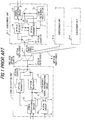
- FIG.1 shows the block diagram of the conventional monitoring equipment. This monitoring equipment for the optical subscriber network system discriminates whether a fault arises on the optical fiber cable or in a subscriber unit, and specifies a faulty circuit in the faulty subscriber unit.
- a motoring equipment for an optical subscriber network system shown in FIG.1 is composed of a center station unit 1, an optical fiber cables, 2 and 4-1 to 4-n, an multiple optical coupler 3 and subscriber units 5-1 to 5-n.
- the center station unit comprises a signal processing circuit 10, an optical transmitter 11, an optical coupler 12, an low frequency signal-discriminating circuit 14 and an alarm circuit 14.
- the optical transmitter 11 transmits down-stream optical signals to the respective subscriber units 5-1 to 5-n.
- the optical receivers 13 receives the up-stream optical signals and optical monitoring signals, both being transmitted from the respective subscriber units 5-1 to 5-n, and supplies them to the signal processing circuit 10.
- the signal processing circuit 10 examininates the existences and the kinds of the up-stream and monitoring signals supplied from the optical receiver 13 and specifies the locations of the faults within the scopes of the optical fibers, 2 and 4-1 to 4-n, and the subscriber units 5-1 to 5-n.
- each of the subscriber unit 5-1 to 5-n comprises an optical receiver 51, which receives and processes the down-stream optical signal directed thereto, a signal processing circuit 52, an optical transmitter 53, which transmits an optical up-stream signal and an optical monitoring signal, and a low frequency signal generator 54.
- the multiple optical coupler 3 splits the down-stream optical signals and supplies them to the subscriber units 5-1 to 5-n, and multiplexes the up-stream optical signals, each being transmitted from the subscriber units.
- the aforementioned monitoring equipment of a simple structure comprises monitoring signal-generating means and monitoring signal-discriminating means, in both of which low frequency analog voltages serves as monitoring signals.
- This equipment can discriminate whether the fault arises on the optical fiber cable or in any one of the subscriber units.
- the monitoring equipment can specify not only a faulty subscriber unit but also a faulty circuit therein, that is to say, discriminate which of the optical signal receiver and the signal processing circuit is faulty.
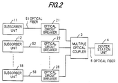
- FIG.2 is a block diagram for showing a preferred embodiment of the invention.
- FIG.2 exemplifies eight subscriber units, which are connected with a center station unit comprising a switch board via eight optical fibers and an multiple optical coupler.
- the system is composed of eight subscriber units 11 to 18, each of which comprises an interface circuit communicated with subscriber terminals, such as telephone sets, and a signal processing circuit for multiplexing electrical signals supplied thereto and E/O-converting them, eight optical circuit breakers 21 to 28 for interrupting optical circuits upon detecting interfering lights, a multiple optical coupler 3 for converting eight branch optical fibers into a single optical fiber, a center station unit 4 for O/E-converting optical signals transmitted through subscriber circuits and demutiplexing and connecting them with a switch board, the eight optical fibers 51 to 58 composing branch optical transmission lines, and an optical fiber 6 communicated with the center station unit 4. Still more, the optical circuit breakers 21 to 28 and the multiple optical coupler 3 are allocated close to each other.
- the subscriber units 11 to 18 are respectively communicated with the center station unit 4 via the eight subscriber circuits independent of each other, each of which transmits bidirectionally multiplexed optical signals.
- the important circuits of the system which play important roles in bidirectional transmission of the multiplexed optical signals are the same as those in the conventional system, detailed description thereon will be omitted, and explanation will be given only on matter concerned with the invention.
- the optical circuit breaker corresponding thereto, any one of 21 to 28, detects the interfering light and interrupts the subscriber circuit concerned.
- an optical signal modulated by a signal of a low frequency, which is sufficiently lower than that of a high bit rate electrical signal, (an optical alarm signal, hereinafter) is supplied to the multiple optical coupler 3 from the optical circuit breaker concerned.
- the center station unit can specify the subscriber unit directly concerned with the intrusion of the interfering light by receiving the optical alarm signal and detecting its modulating frequency.
- FIG.3 is a block diagram for showing the structure of the optical circuit breaker.
- the optical circuit breaker 21 The functions of structural element composing the optical circuit breaker 21 are explained as follows.
- An three port optical coupler 201 splits an optical signal supplied from the subscriber unit 11 into two optical signals.
- An optical delay circuit delays one of the two split optical signals by a time necessary for detecting the existence of the interfering light.
- a photodiode 204 converts the other one of the two split optical signals into an electrical signal.
- An amplifier 205 amplifies the output current of the photodiode 204 and converts it into a volage signal.
- a high level component-detecting circuit 206 is supplied with the output of the amplifier 205, and generates an output signal, when the output of the amplifier 205 exceeds a threshode level.
- a low frequency component-detecting circuit 207 is supplied with the output of the amplifier 205, and generates an output signal, when low frequency component including DC with a level exceeding a predetermined value, which is derived in consideration of the level of a high bit rate signal component involved in the output of the amplifier 205.
- An OR circuit 208 generates a logical sum of the output signals of the high level component-detecting circuit 206 and the low frequency component-detecting circuit 207.
- An optical alarm signal generator 209 generates an optical signal modulated by a low frequency signal, the frequency of which is sufficiently lower than that of the high bit rate electrical signal.
- An optical switch 203 is supplied with the output optical signals of the optical delay circuit 202 and the optical alarm signal generator 209, and transmits the output of the optical delay circuit 202, when the output of the OR circuit 208 is not supplied thereto; and transmits the output of the optical alarm signal generator 209, when the output of the OR circuit 208 is supplied thereto.
- the optical signal supplied from the subscriber unit 11 is split into two optical signals by the three port optical coupler 201.
- One of the two split optical signals is deayed by the optical delay circuit 202 and supplied to the optical switch 203.
- the other one of the tow split optical signals is converted into an electrical signal by the photodiode 204 and supplied to the amplifier 205. Since the electrical signal generated by the photodiode 204 is slight, it is amplified by the amplifier 205 and converted into a voltage signal.
- the voltage signal is supplied to the high level component-detecting circuit 206 and the low frequency component-detecting circuit 207 in parallel.
- the extraordinariness of the optical signal in other words, the existence of the interfering light, can discriminated through the detection of the high level component or the low frequency component of the output of the amplifier 205.
- the logical sum of the outputs of the high level component-detecting 206 and the low frequency component-detecting circuit 207 can be given by the OR circuit 208, and supplied to the optical switch 203.
- the output of the optical delay circuit 202 is supplied to the optical switch 203 and passes therethrogh.
- the output of the optical switch 203 is change into the optical alarm signal. Since a few time is necessary for detecting the interfering light, the optical delay circuit 202 delays the optical signal by the aforementioned time, hence a momentary leakage of the interfering light into the output of the optical switch 203 can be prevented.
- the center station unit 4 can immediately specifies the subscriber unit, into which the interfering light intrudes.
- the optical subscriber network system detects the intrusion of the interfering light by the optical circuit breaker and interrupts the subscriber circuit concerned, the effects of the interfering light on the other subscriber units can be perfectly prevented.
Landscapes
- Engineering & Computer Science (AREA)
- Physics & Mathematics (AREA)
- Electromagnetism (AREA)
- Computer Networks & Wireless Communication (AREA)
- Signal Processing (AREA)
- Computing Systems (AREA)
- Optical Communication System (AREA)
- Monitoring And Testing Of Transmission In General (AREA)
Applications Claiming Priority (2)
| Application Number | Priority Date | Filing Date | Title |
|---|---|---|---|
| JP9107389A JP3056116B2 (ja) | 1997-04-24 | 1997-04-24 | 光加入者システム |
| JP107389/97 | 1997-04-24 |
Publications (1)
| Publication Number | Publication Date |
|---|---|
| EP0874481A2 true EP0874481A2 (de) | 1998-10-28 |
Family
ID=14457900
Family Applications (1)
| Application Number | Title | Priority Date | Filing Date |
|---|---|---|---|
| EP98107517A Withdrawn EP0874481A2 (de) | 1997-04-24 | 1998-04-24 | Optisches Teilnehmer-Anschlussnetzsystem |
Country Status (2)
| Country | Link |
|---|---|
| EP (1) | EP0874481A2 (de) |
| JP (1) | JP3056116B2 (de) |
Cited By (2)
| Publication number | Priority date | Publication date | Assignee | Title |
|---|---|---|---|---|
| US20090310964A1 (en) * | 2008-06-12 | 2009-12-17 | Hitachi Communication Technologies, Ltd. | Optical communication system and optical line terminating apparatus |
| CN113630177A (zh) * | 2021-06-29 | 2021-11-09 | 岳阳索非特矿山机械有限责任公司 | 一种光纤串联通信系统以及通信网络系统 |
Families Citing this family (3)
| Publication number | Priority date | Publication date | Assignee | Title |
|---|---|---|---|---|
| JP4509398B2 (ja) * | 2001-01-16 | 2010-07-21 | 三菱電機株式会社 | 光バースト送受信制御システムおよびその方法 |
| TWI353741B (en) | 2007-10-31 | 2011-12-01 | Ind Tech Res Inst | Prevention of collision for time division multiple |
| JP2014220600A (ja) * | 2013-05-02 | 2014-11-20 | 日本電信電話株式会社 | 高速波長変化モニタおよびこれを用いた光遮断装置 |
-
1997
- 1997-04-24 JP JP9107389A patent/JP3056116B2/ja not_active Expired - Lifetime
-
1998
- 1998-04-24 EP EP98107517A patent/EP0874481A2/de not_active Withdrawn
Cited By (3)
| Publication number | Priority date | Publication date | Assignee | Title |
|---|---|---|---|---|
| US20090310964A1 (en) * | 2008-06-12 | 2009-12-17 | Hitachi Communication Technologies, Ltd. | Optical communication system and optical line terminating apparatus |
| US8249454B2 (en) * | 2008-06-12 | 2012-08-21 | Hitachi, Ltd. | Optical communication system and optical line terminating apparatus |
| CN113630177A (zh) * | 2021-06-29 | 2021-11-09 | 岳阳索非特矿山机械有限责任公司 | 一种光纤串联通信系统以及通信网络系统 |
Also Published As
| Publication number | Publication date |
|---|---|
| JPH10303817A (ja) | 1998-11-13 |
| JP3056116B2 (ja) | 2000-06-26 |
Similar Documents
| Publication | Publication Date | Title |
|---|---|---|
| US10560185B2 (en) | Optical line card with optical signal power monitor | |
| US5914794A (en) | Method of and apparatus for detecting and reporting faults in an all-optical communications system | |
| EP0392490B1 (de) | Optische Verzweigungsvorrichtung und deren Verwendung in einem optischen Netzwerk | |
| US4517619A (en) | Protective relay system for a power system | |
| EP0903875A2 (de) | Automatisches Leistungsabschaltungssystem einer optischen Übertragungsstrecke | |
| US20060029390A1 (en) | Optical distribution network monitoring method and system | |
| WO1997024823A2 (en) | Method and system for transporting ancillary network data | |
| EP1004184B1 (de) | Selbstheilendes ringnetz und verfahren zur fehlererkennung und behebung | |
| US7016609B2 (en) | Receiver transponder for protected networks | |
| JPH10107772A (ja) | 光ネットワークシステムのパス監視装置 | |
| EP0874481A2 (de) | Optisches Teilnehmer-Anschlussnetzsystem | |
| EP0385649B1 (de) | Faseroptisches Übertragungssystem | |
| CA1163025A (en) | Service integrated digital transmission system | |
| US6839515B1 (en) | Method for establishing a communication on a standby link in optical transmission facilities | |
| GB2429352A (en) | Optical communication system which can detect multiple types of faults, and generate an alarm signal whose frequency identifies the type of fault | |
| US5623321A (en) | Circuit for cutting off power to an active RF component | |
| KR100340726B1 (ko) | 역방향 광링크 감시에 의한 자동광원차단 장치 | |
| JP2781720B2 (ja) | 光加入者システム監視方式 | |
| JPH04232438A (ja) | 光伝送装置 | |
| JP2752891B2 (ja) | 光加入者システム監視方式 | |
| JP2025052807A (ja) | 反射光検出装置および反射光検出方法 | |
| JP2550878B2 (ja) | 光送受信回路 | |
| JP2000304647A (ja) | 反射光検出装置及び方法、光加入者伝送装置、並びに光加入者システム | |
| JP2529451B2 (ja) | 光通信ユニット | |
| JPH04276928A (ja) | 光多重化端局装置 |
Legal Events
| Date | Code | Title | Description |
|---|---|---|---|
| PUAI | Public reference made under article 153(3) epc to a published international application that has entered the european phase |
Free format text: ORIGINAL CODE: 0009012 |
|
| AK | Designated contracting states |
Kind code of ref document: A2 Designated state(s): AT BE CH CY DE DK ES FI FR GB GR IE IT LI LU MC NL PT SE |
|
| AX | Request for extension of the european patent |
Free format text: AL;LT;LV;MK;RO;SI |
|
| STAA | Information on the status of an ep patent application or granted ep patent |
Free format text: STATUS: THE APPLICATION HAS BEEN WITHDRAWN |
|
| 18W | Application withdrawn |
Effective date: 20021209 |