EP0874794B1 - Herstellung von 1,1-difluorethan - Google Patents
Herstellung von 1,1-difluorethan Download PDFInfo
- Publication number
- EP0874794B1 EP0874794B1 EP97901949A EP97901949A EP0874794B1 EP 0874794 B1 EP0874794 B1 EP 0874794B1 EP 97901949 A EP97901949 A EP 97901949A EP 97901949 A EP97901949 A EP 97901949A EP 0874794 B1 EP0874794 B1 EP 0874794B1
- Authority
- EP
- European Patent Office
- Prior art keywords
- reactor
- tin
- chloroethene
- hfc
- sncl
- Prior art date
- Legal status (The legal status is an assumption and is not a legal conclusion. Google has not performed a legal analysis and makes no representation as to the accuracy of the status listed.)
- Expired - Lifetime
Links
- NPNPZTNLOVBDOC-UHFFFAOYSA-N 1,1-difluoroethane Chemical compound CC(F)F NPNPZTNLOVBDOC-UHFFFAOYSA-N 0.000 title claims abstract description 81
- 238000004519 manufacturing process Methods 0.000 title claims description 6
- 238000000034 method Methods 0.000 claims abstract description 82
- BZHJMEDXRYGGRV-UHFFFAOYSA-N Vinyl chloride Chemical compound ClC=C BZHJMEDXRYGGRV-UHFFFAOYSA-N 0.000 claims abstract description 77
- KRHYYFGTRYWZRS-UHFFFAOYSA-N Fluorane Chemical compound F KRHYYFGTRYWZRS-UHFFFAOYSA-N 0.000 claims abstract description 65
- 229910000040 hydrogen fluoride Inorganic materials 0.000 claims abstract description 64
- 239000012974 tin catalyst Substances 0.000 claims abstract description 45
- 229910001508 alkali metal halide Inorganic materials 0.000 claims abstract description 44
- 150000008045 alkali metal halides Chemical class 0.000 claims abstract description 44
- 150000008282 halocarbons Chemical class 0.000 claims abstract description 36
- 229920006395 saturated elastomer Polymers 0.000 claims abstract description 34
- 150000001875 compounds Chemical class 0.000 claims abstract description 19
- 239000007791 liquid phase Substances 0.000 claims abstract description 9
- 229910021627 Tin(IV) chloride Inorganic materials 0.000 claims description 30
- HPGGPRDJHPYFRM-UHFFFAOYSA-J tin(iv) chloride Chemical compound Cl[Sn](Cl)(Cl)Cl HPGGPRDJHPYFRM-UHFFFAOYSA-J 0.000 claims description 30
- YMWUJEATGCHHMB-UHFFFAOYSA-N Dichloromethane Chemical compound ClCCl YMWUJEATGCHHMB-UHFFFAOYSA-N 0.000 claims description 21
- 239000003054 catalyst Substances 0.000 claims description 16
- 239000000203 mixture Substances 0.000 claims description 16
- 238000010438 heat treatment Methods 0.000 claims description 15
- ATJFFYVFTNAWJD-UHFFFAOYSA-N Tin Chemical compound [Sn] ATJFFYVFTNAWJD-UHFFFAOYSA-N 0.000 claims description 11
- FAPWRFPIFSIZLT-UHFFFAOYSA-M Sodium chloride Chemical compound [Na+].[Cl-] FAPWRFPIFSIZLT-UHFFFAOYSA-M 0.000 claims description 10
- 239000000460 chlorine Substances 0.000 claims description 10
- SCYULBFZEHDVBN-UHFFFAOYSA-N 1,1-Dichloroethane Chemical compound CC(Cl)Cl SCYULBFZEHDVBN-UHFFFAOYSA-N 0.000 claims description 9
- 229910021626 Tin(II) chloride Inorganic materials 0.000 claims description 9
- -1 tin halide Chemical class 0.000 claims description 9
- 229910052801 chlorine Inorganic materials 0.000 claims description 8
- 229910052731 fluorine Inorganic materials 0.000 claims description 7
- YACLCMMBHTUQON-UHFFFAOYSA-N 1-chloro-1-fluoroethane Chemical compound CC(F)Cl YACLCMMBHTUQON-UHFFFAOYSA-N 0.000 claims description 5
- 229910052794 bromium Inorganic materials 0.000 claims description 5
- 238000010924 continuous production Methods 0.000 claims description 5
- 239000011737 fluorine Substances 0.000 claims description 5
- 229910052739 hydrogen Inorganic materials 0.000 claims description 5
- 239000011780 sodium chloride Substances 0.000 claims description 5
- WSLDOOZREJYCGB-UHFFFAOYSA-N 1,2-Dichloroethane Chemical compound ClCCCl WSLDOOZREJYCGB-UHFFFAOYSA-N 0.000 claims description 4
- PXGOKWXKJXAPGV-UHFFFAOYSA-N Fluorine Chemical compound FF PXGOKWXKJXAPGV-UHFFFAOYSA-N 0.000 claims description 4
- VXKWYPOMXBVZSJ-UHFFFAOYSA-N tetramethyltin Chemical compound C[Sn](C)(C)C VXKWYPOMXBVZSJ-UHFFFAOYSA-N 0.000 claims description 4
- OHMHBGPWCHTMQE-UHFFFAOYSA-N 2,2-dichloro-1,1,1-trifluoroethane Chemical compound FC(F)(F)C(Cl)Cl OHMHBGPWCHTMQE-UHFFFAOYSA-N 0.000 claims description 3
- WKBOTKDWSSQWDR-UHFFFAOYSA-N Bromine atom Chemical compound [Br] WKBOTKDWSSQWDR-UHFFFAOYSA-N 0.000 claims description 3
- 229910009201 Sn(CH3)4 Inorganic materials 0.000 claims description 3
- 229910021623 Tin(IV) bromide Inorganic materials 0.000 claims description 3
- GDTBXPJZTBHREO-UHFFFAOYSA-N bromine Substances BrBr GDTBXPJZTBHREO-UHFFFAOYSA-N 0.000 claims description 3
- 239000001257 hydrogen Substances 0.000 claims description 3
- AXZWODMDQAVCJE-UHFFFAOYSA-L tin(II) chloride (anhydrous) Chemical compound [Cl-].[Cl-].[Sn+2] AXZWODMDQAVCJE-UHFFFAOYSA-L 0.000 claims description 3
- LTSUHJWLSNQKIP-UHFFFAOYSA-J tin(iv) bromide Chemical compound Br[Sn](Br)(Br)Br LTSUHJWLSNQKIP-UHFFFAOYSA-J 0.000 claims description 3
- ZAMOUSCENKQFHK-UHFFFAOYSA-N Chlorine atom Chemical compound [Cl] ZAMOUSCENKQFHK-UHFFFAOYSA-N 0.000 claims description 2
- 125000001309 chloro group Chemical group Cl* 0.000 claims description 2
- 125000004435 hydrogen atom Chemical class [H]* 0.000 claims 2
- 238000006243 chemical reaction Methods 0.000 abstract description 13
- 238000002360 preparation method Methods 0.000 abstract description 5
- IJGRMHOSHXDMSA-UHFFFAOYSA-N Atomic nitrogen Chemical compound N#N IJGRMHOSHXDMSA-UHFFFAOYSA-N 0.000 description 32
- 239000000654 additive Substances 0.000 description 24
- VNWKTOKETHGBQD-UHFFFAOYSA-N methane Chemical compound C VNWKTOKETHGBQD-UHFFFAOYSA-N 0.000 description 24
- 239000011269 tar Substances 0.000 description 24
- 238000010992 reflux Methods 0.000 description 23
- 229910052718 tin Inorganic materials 0.000 description 19
- 230000000996 additive effect Effects 0.000 description 17
- 239000000463 material Substances 0.000 description 17
- 239000007788 liquid Substances 0.000 description 16
- 229910052757 nitrogen Inorganic materials 0.000 description 16
- 230000000052 comparative effect Effects 0.000 description 15
- 238000002474 experimental method Methods 0.000 description 15
- 239000000047 product Substances 0.000 description 14
- 230000015572 biosynthetic process Effects 0.000 description 12
- 239000003039 volatile agent Substances 0.000 description 10
- 239000006227 byproduct Substances 0.000 description 9
- 230000001965 increasing effect Effects 0.000 description 9
- 239000002585 base Substances 0.000 description 8
- 238000004817 gas chromatography Methods 0.000 description 8
- 229910052751 metal Inorganic materials 0.000 description 8
- 239000002184 metal Substances 0.000 description 8
- VEXZGXHMUGYJMC-UHFFFAOYSA-N Hydrochloric acid Chemical compound Cl VEXZGXHMUGYJMC-UHFFFAOYSA-N 0.000 description 7
- UJPMYEOUBPIPHQ-UHFFFAOYSA-N 1,1,1-trifluoroethane Chemical compound CC(F)(F)F UJPMYEOUBPIPHQ-UHFFFAOYSA-N 0.000 description 6
- 239000007789 gas Substances 0.000 description 6
- NROKBHXJSPEDAR-UHFFFAOYSA-M potassium fluoride Chemical compound [F-].[K+] NROKBHXJSPEDAR-UHFFFAOYSA-M 0.000 description 6
- 239000011698 potassium fluoride Substances 0.000 description 6
- 229910001220 stainless steel Inorganic materials 0.000 description 6
- GETQZCLCWQTVFV-UHFFFAOYSA-N trimethylamine Chemical compound CN(C)C GETQZCLCWQTVFV-UHFFFAOYSA-N 0.000 description 6
- BHNZEZWIUMJCGF-UHFFFAOYSA-N 1-chloro-1,1-difluoroethane Chemical compound CC(F)(F)Cl BHNZEZWIUMJCGF-UHFFFAOYSA-N 0.000 description 5
- 238000010923 batch production Methods 0.000 description 5
- 238000001816 cooling Methods 0.000 description 5
- 239000000498 cooling water Substances 0.000 description 5
- 229910000856 hastalloy Inorganic materials 0.000 description 5
- 239000007787 solid Substances 0.000 description 5
- 239000010935 stainless steel Substances 0.000 description 5
- UOCLXMDMGBRAIB-UHFFFAOYSA-N 1,1,1-trichloroethane Chemical compound CC(Cl)(Cl)Cl UOCLXMDMGBRAIB-UHFFFAOYSA-N 0.000 description 4
- WAIPAZQMEIHHTJ-UHFFFAOYSA-N [Cr].[Co] Chemical compound [Cr].[Co] WAIPAZQMEIHHTJ-UHFFFAOYSA-N 0.000 description 4
- 238000004458 analytical method Methods 0.000 description 4
- 230000003247 decreasing effect Effects 0.000 description 4
- 230000010354 integration Effects 0.000 description 4
- 239000000543 intermediate Substances 0.000 description 4
- SYRHIZPPCHMRIT-UHFFFAOYSA-N tin(4+) Chemical compound [Sn+4] SYRHIZPPCHMRIT-UHFFFAOYSA-N 0.000 description 4
- XLYOFNOQVPJJNP-UHFFFAOYSA-N water Substances O XLYOFNOQVPJJNP-UHFFFAOYSA-N 0.000 description 4
- 238000004876 x-ray fluorescence Methods 0.000 description 4
- 239000007795 chemical reaction product Substances 0.000 description 3
- 238000004821 distillation Methods 0.000 description 3
- 238000009826 distribution Methods 0.000 description 3
- 229910052736 halogen Inorganic materials 0.000 description 3
- 230000001404 mediated effect Effects 0.000 description 3
- 235000003270 potassium fluoride Nutrition 0.000 description 3
- PUZPDOWCWNUUKD-UHFFFAOYSA-M sodium fluoride Inorganic materials [F-].[Na+] PUZPDOWCWNUUKD-UHFFFAOYSA-M 0.000 description 3
- 238000003786 synthesis reaction Methods 0.000 description 3
- 238000012546 transfer Methods 0.000 description 3
- FRCHKSNAZZFGCA-UHFFFAOYSA-N 1,1-dichloro-1-fluoroethane Chemical compound CC(F)(Cl)Cl FRCHKSNAZZFGCA-UHFFFAOYSA-N 0.000 description 2
- OKTJSMMVPCPJKN-UHFFFAOYSA-N Carbon Chemical compound [C] OKTJSMMVPCPJKN-UHFFFAOYSA-N 0.000 description 2
- PXHVJJICTQNCMI-UHFFFAOYSA-N Nickel Chemical compound [Ni] PXHVJJICTQNCMI-UHFFFAOYSA-N 0.000 description 2
- 238000013019 agitation Methods 0.000 description 2
- QVGXLLKOCUKJST-UHFFFAOYSA-N atomic oxygen Chemical compound [O] QVGXLLKOCUKJST-UHFFFAOYSA-N 0.000 description 2
- 229910052799 carbon Inorganic materials 0.000 description 2
- 238000004891 communication Methods 0.000 description 2
- 239000000539 dimer Substances 0.000 description 2
- 230000000694 effects Effects 0.000 description 2
- 239000000706 filtrate Substances 0.000 description 2
- 239000012530 fluid Substances 0.000 description 2
- 238000003682 fluorination reaction Methods 0.000 description 2
- 150000002367 halogens Chemical group 0.000 description 2
- 239000011344 liquid material Substances 0.000 description 2
- 239000001301 oxygen Substances 0.000 description 2
- 229910052760 oxygen Inorganic materials 0.000 description 2
- 238000010926 purge Methods 0.000 description 2
- 150000003839 salts Chemical class 0.000 description 2
- 238000005070 sampling Methods 0.000 description 2
- 239000011775 sodium fluoride Substances 0.000 description 2
- 125000001424 substituent group Chemical group 0.000 description 2
- LGXVIGDEPROXKC-UHFFFAOYSA-N 1,1-dichloroethene Chemical compound ClC(Cl)=C LGXVIGDEPROXKC-UHFFFAOYSA-N 0.000 description 1
- ZCYVEMRRCGMTRW-UHFFFAOYSA-N 7553-56-2 Chemical compound [I] ZCYVEMRRCGMTRW-UHFFFAOYSA-N 0.000 description 1
- 239000004604 Blowing Agent Substances 0.000 description 1
- 229910000881 Cu alloy Inorganic materials 0.000 description 1
- UFHFLCQGNIYNRP-UHFFFAOYSA-N Hydrogen Chemical compound [H][H] UFHFLCQGNIYNRP-UHFFFAOYSA-N 0.000 description 1
- DGAQECJNVWCQMB-PUAWFVPOSA-M Ilexoside XXIX Chemical compound C[C@@H]1CC[C@@]2(CC[C@@]3(C(=CC[C@H]4[C@]3(CC[C@@H]5[C@@]4(CC[C@@H](C5(C)C)OS(=O)(=O)[O-])C)C)[C@@H]2[C@]1(C)O)C)C(=O)O[C@H]6[C@@H]([C@H]([C@@H]([C@H](O6)CO)O)O)O.[Na+] DGAQECJNVWCQMB-PUAWFVPOSA-M 0.000 description 1
- WHXSMMKQMYFTQS-UHFFFAOYSA-N Lithium Chemical compound [Li] WHXSMMKQMYFTQS-UHFFFAOYSA-N 0.000 description 1
- 229910000792 Monel Inorganic materials 0.000 description 1
- 229910000990 Ni alloy Inorganic materials 0.000 description 1
- CBENFWSGALASAD-UHFFFAOYSA-N Ozone Chemical compound [O-][O+]=O CBENFWSGALASAD-UHFFFAOYSA-N 0.000 description 1
- ZLMJMSJWJFRBEC-UHFFFAOYSA-N Potassium Chemical compound [K] ZLMJMSJWJFRBEC-UHFFFAOYSA-N 0.000 description 1
- 229920006362 Teflon® Polymers 0.000 description 1
- LCKIEQZJEYYRIY-UHFFFAOYSA-N Titanium ion Chemical compound [Ti+4] LCKIEQZJEYYRIY-UHFFFAOYSA-N 0.000 description 1
- TXTQARDVRPFFHL-UHFFFAOYSA-N [Sb].[H][H] Chemical compound [Sb].[H][H] TXTQARDVRPFFHL-UHFFFAOYSA-N 0.000 description 1
- RYBNIBRDTOTBMV-UHFFFAOYSA-N [Sn].ClF Chemical compound [Sn].ClF RYBNIBRDTOTBMV-UHFFFAOYSA-N 0.000 description 1
- 229910052783 alkali metal Inorganic materials 0.000 description 1
- 150000001340 alkali metals Chemical class 0.000 description 1
- 229910045601 alloy Inorganic materials 0.000 description 1
- 239000000956 alloy Substances 0.000 description 1
- ZDINGUUTWDGGFF-UHFFFAOYSA-N antimony(5+) Chemical compound [Sb+5] ZDINGUUTWDGGFF-UHFFFAOYSA-N 0.000 description 1
- 230000009286 beneficial effect Effects 0.000 description 1
- 238000009835 boiling Methods 0.000 description 1
- 229910052792 caesium Inorganic materials 0.000 description 1
- TVFDJXOCXUVLDH-UHFFFAOYSA-N caesium atom Chemical compound [Cs] TVFDJXOCXUVLDH-UHFFFAOYSA-N 0.000 description 1
- 150000001721 carbon Chemical class 0.000 description 1
- 125000004432 carbon atom Chemical group C* 0.000 description 1
- 230000003197 catalytic effect Effects 0.000 description 1
- 239000003153 chemical reaction reagent Substances 0.000 description 1
- 239000000788 chromium alloy Substances 0.000 description 1
- 239000012459 cleaning agent Substances 0.000 description 1
- 238000009833 condensation Methods 0.000 description 1
- 230000005494 condensation Effects 0.000 description 1
- 238000010276 construction Methods 0.000 description 1
- YOCUPQPZWBBYIX-UHFFFAOYSA-N copper nickel Chemical compound [Ni].[Cu] YOCUPQPZWBBYIX-UHFFFAOYSA-N 0.000 description 1
- 230000002939 deleterious effect Effects 0.000 description 1
- 230000001627 detrimental effect Effects 0.000 description 1
- 238000010586 diagram Methods 0.000 description 1
- PKKGKUDPKRTKLJ-UHFFFAOYSA-L dichloro(dimethyl)stannane Chemical compound C[Sn](C)(Cl)Cl PKKGKUDPKRTKLJ-UHFFFAOYSA-L 0.000 description 1
- 239000003085 diluting agent Substances 0.000 description 1
- 230000009977 dual effect Effects 0.000 description 1
- 230000002708 enhancing effect Effects 0.000 description 1
- XUCNUKMRBVNAPB-UHFFFAOYSA-N fluoroethene Chemical compound FC=C XUCNUKMRBVNAPB-UHFFFAOYSA-N 0.000 description 1
- NBVXSUQYWXRMNV-UHFFFAOYSA-N fluoromethane Chemical class FC NBVXSUQYWXRMNV-UHFFFAOYSA-N 0.000 description 1
- 238000004442 gravimetric analysis Methods 0.000 description 1
- 229910001026 inconel Inorganic materials 0.000 description 1
- 229910052740 iodine Inorganic materials 0.000 description 1
- 239000011630 iodine Substances 0.000 description 1
- 229910052744 lithium Inorganic materials 0.000 description 1
- 239000012528 membrane Substances 0.000 description 1
- 150000002739 metals Chemical class 0.000 description 1
- 238000012986 modification Methods 0.000 description 1
- 230000004048 modification Effects 0.000 description 1
- 229910052759 nickel Inorganic materials 0.000 description 1
- 229910000623 nickel–chromium alloy Inorganic materials 0.000 description 1
- 239000003921 oil Substances 0.000 description 1
- 239000003960 organic solvent Substances 0.000 description 1
- 230000000737 periodic effect Effects 0.000 description 1
- 239000012071 phase Substances 0.000 description 1
- 229920000642 polymer Polymers 0.000 description 1
- 238000006116 polymerization reaction Methods 0.000 description 1
- 229910052700 potassium Inorganic materials 0.000 description 1
- 239000011591 potassium Substances 0.000 description 1
- 239000003380 propellant Substances 0.000 description 1
- 239000011541 reaction mixture Substances 0.000 description 1
- 239000003507 refrigerant Substances 0.000 description 1
- 239000011369 resultant mixture Substances 0.000 description 1
- 229910052701 rubidium Inorganic materials 0.000 description 1
- IGLNJRXAVVLDKE-UHFFFAOYSA-N rubidium atom Chemical compound [Rb] IGLNJRXAVVLDKE-UHFFFAOYSA-N 0.000 description 1
- 229910052708 sodium Inorganic materials 0.000 description 1
- 239000011734 sodium Substances 0.000 description 1
- 235000013024 sodium fluoride Nutrition 0.000 description 1
- 238000010561 standard procedure Methods 0.000 description 1
- 239000007858 starting material Substances 0.000 description 1
- 239000000725 suspension Substances 0.000 description 1
- 150000003606 tin compounds Chemical class 0.000 description 1
- 239000013638 trimer Substances 0.000 description 1
Images
Classifications
-
- C—CHEMISTRY; METALLURGY
- C07—ORGANIC CHEMISTRY
- C07C—ACYCLIC OR CARBOCYCLIC COMPOUNDS
- C07C17/00—Preparation of halogenated hydrocarbons
- C07C17/093—Preparation of halogenated hydrocarbons by replacement by halogens
- C07C17/20—Preparation of halogenated hydrocarbons by replacement by halogens of halogen atoms by other halogen atoms
- C07C17/21—Preparation of halogenated hydrocarbons by replacement by halogens of halogen atoms by other halogen atoms with simultaneous increase of the number of halogen atoms
Definitions
- the present invention relates to processes for the selective and high yield preparation of 1,1-difluoroethane, and more particularly, to such processes which comprise contacting chloroethene with hydrogen fluoride in a liquid phase while in the presence of a tin catalyst, and at least one of an alkali metal halide, and a saturated halogenated hydrocarbon.
- HFCs hydrofluorocarbons
- HCCs hydrochlorocarbons
- Komatsu et al. in U.S. Patent No. 4,766,258, disclose a process for the manufacture of HFCs and hydrochlorofluorocarbons (HCFCs) by allowing HCCs to react with anhydrous HF in the presence of a tin catalyst and an additive chosen from compounds containing oxygen or nitrogen.
- Komatsu et al. in Japanese Kokai publication number SHO 62[1987]-246528, disclose a process for the manufacture of HFCs and HCFCs characterized by allowing a hydrogen-containing halogenated hydrocarbon to react with HF in a liquid phase in the presence of the reaction product from a compound acting as a base in HF, a tin catalyst, and HF.
- Pennetreau et al. in European patent application EP 637,579, disclose a method for the preparation of either 1-chloro-1-fluoroethane (HCFC-151a) or HFC-152a by reaction of chloroethene with HF in the presence of a metal catalyst and an organic solvent composed of at least one saturated halogenated hydrocarbon.
- HFC-152a or 152a 1,1-Difluoroethane, hereinafter referred to as HFC-152a or 152a, is a compound of considerable utility. It may be used either alone or in blends with other materials as a refrigerant, blowing agent, propellant, cleaning agent, or as an intermediate for other fluorocarbon compounds, such as fluoroethene.
- HFCs such as HFC-152a are environmentally acceptable replacements for chlorofluorocarbons (CFCs), since they have no known effect on the earth's stratospheric ozone.
- HFC-152a has been manufactured in this manner using liquid and gas phase processes.
- the literature reveals that HFC-152a has been prepared by allowing chloroethene to react with HF in the presence of salts of various oxidized metals such as tin(IV), titanium(IV), antimony(III), and antimony(V).
- HFC-152a is prepared from chloroethene comprise 1-chloro-1-fluoroethane (HCFC-151a, or 151 a) and 1,1-dichloroethane (HCC-150a, or 150a).
- Byproducts of such conventional procedures include an assortment of oligomeric and polymeric materials; low molecular weight halogenated dimers and oligomers through higher molecular weight halogenated polymers taking the form of oils, tars, and dark carbonaceous solids.
- These byproducts are typically higher molecular weight, e.g., predominately 50,000, with standard weight fraction distribution from 2,000 to 75,000 number averaged molecular weight, branched, polymeric, halogenated hydrocarbons, which may contain metal species acquired from catalyst and other additives, if present.
- Such higher molecular weight materials can be formed by polymerization of lower molecular weight dimers, trimers, and oligomers with themselves or with the halogenated carbon-containing reagents and their fluorinated adducts.
- These byproducts are detrimental to the exchange process as they interfere with catalyst activity, reduce reactor volume, decrease the yield of HFC-152a, and are a disposal concern.
- the ideal additive for the exchange process is one which minimizes byproduct formation while enhancing the reaction rate and increasing selectivity towards the desired product.
- the present invention is a process for producing HFC-152a comprising providing a liquid phase containing chloroethene, HF, tin catalyst, at least one compound selected from the group consisting of alkali metal halide and saturated halogenated hydrocarbon the saturated halogenated hydrocarbon constituting less than 55 weight percent of the liquid phase mixture; heating the mixture; and isolating the HFC-152a formed.
- the reaction components may be charged to a reaction vessel in any order, but preferably, the vessel is first charged with tin catalyst, HF, alkali metal halide, and saturated halogenated hydrocarbon. The temperature of this mixture is maintained from 30°C to 160°C over the reaction period. During this period, chloroethene is added and is converted to HCFC-151a under the reaction conditions. This HCFC-151a then undergoes fluorine for chlorine halogen exchange under the reaction conditions and product HFC-152a distills out of the reaction mixture.
- the process of the present invention can be operated as a batch process. It is perferrable to operate a continuous process by the continuous addition of HF, tin catalyst, alkali metal halide, and saturated halogenated hydrocarbon to the reaction vessel along with chloroethene accompanied by the removal of HFC-152a and HCl.
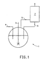
- Figure 1 is a schematic drawing of one embodiment of the process of this invention.
- This invention is a process for the selective and high yield synthesis of HFC-152a from chloroethene while minimizing the formation of byproducts.
- the process comprises: providing a mixture comprising chloroethene. HF, at least one tin catalyst, and at least one compound selected from the group consisting of alkali metal halide and saturated halogenated hydrocarbon, heating the mixture, and isolating the HFC-152a formed.
- Results obtained in this study are summarized in Tables 1 and 2, and reveal the benefits of employing alkali metal halide and saturated halogenated hydrocarbon in the tin(IV) mediated synthesis of HFC-152a from chloroethene and HF.
- Tin catalysts for use in the process of the present invention are selected from the families of tin halides, tin oxyhalides, and organotins. Of the three families, the tin halides are preferred, and of the tin halides, tin(IV) chloride (SnCl 4 , stannic chloride) is most preferred. Other acceptable tin(IV) halides include SnBr 4 and the series of SnCl 3 F, SnCl 2 F 2 , SnClF 3 , and SnF 4 ; such species as are generated when SnCl 4 is allowed to react with HF.
- organotins are compounds in which the tin atom is bonded to from one to four carbon atoms.
- Organotin compounds such as tetramethyl tin (Sn(CH 3 ) 4 ), oxydiethyl tin (OSn(C 2 H 5 ) 2 ), and dichlorodimethyl tin (SnCl 2 (CH 3 ) 2 ) are acceptable.
- Alkali metal halides for use in the process of the present invention are of the general empirical formula MX; where M is a group IA alkali metal (where group IA pertains to the said group in the standard periodic table of the elements, such as that represented upon the inner front cover of Lang's Handbook of Chemistry, fourteenth edition, John A. Dean Ed., McGraw Hill, Inc., 1992).
- the metal M may be lithium, sodium, potassium, rubidium, or cesium
- X is a group VIIA halogen such as fluorine, chlorine, bromine, or iodine.
- compounds such as NaCI, KF, KCl, and NaF are preferred; NaCI is most preferred.
- the quantity of at least one alkali metal halide that may be used in the process of the present invention is between 0.001 mole to 2 moles per mole of tin catalyst.
- the process is carried out using between 0.1 mole to 1.5 moles of at least one alkali metal halide per mole of tin catalyst.
- one or more of the aforementioned alkali metal halides and tin catalysts can be combined prior to being contacted with chloroethene.
- NaCI and SnCl 4 are premixed, e.g., a suspension NaCl/SnCl 4 .
- the premixed alkali metal halide/tin catalyst combination can be employed in any suitable batch or continuous process described herein.
- Saturated halogenated hydrocarbons for use in the process of the present invention are selected from the general family CX 1 X 2 X 3 X 4 , wherein at least one of X 1 through X 4 is chlorine, and wherein the remainder of X 1 through X 4 substituents are identical or different and are selected from the group consisting of H, F, Cl, Br, or C y Z (2y+1) , wherein substituents Z are identical or different and are selected from the group consisting of H, F, Cl, or Br, and y is an integer from 1 to 6.
- the saturated halogenated hydrocarbons of the present invention are preferrably methylene chloride (CH 2 Cl 2 ), 1,2-dichloroethane (CH 2 Cl-CH 2 Cl), 1,1-dichloroethane (CHCl 2 -CH 3 , HCC-150a), 1-chloro-1-fluoroethane (CHFCl-CH 3 , HCFC-151a), and 2,2-dichloro-1,1,1-trifluoroethane (CF 3 -CHCl 2 , HCFC-123).
- the saturated halogenated hydrocarbon may be charged to the reactor as one or more pure compounds or in any mixture composed of several compounds.
- the quantity of at least one saturated halogenated hydrocarbon used in the process of the present invention may be from 0.001 mole to 5 moles per mole of tin catalyst.
- the process is preferably carried out using from 0.1 mole to 3 moles saturated halogenated hydrocarbon per mole of tin catalyst; and most preferably from 0.5 to 1.5 moles per mole of tin catalyst.
- Table 1 summarizes results obtained, further reported in the Examples, by operating one aspect of the inventive process.
- Table 1 illustrates the benefits of employing an alkali metal halide in the tin(IV) mediated synthesis of HFC-152a from chloroethene and HF. Holding all other process variables constant and increasing the mole ratio of alkali metal halide to tin catalyst from 0 to 1 causes a corresponding increase in the HFC-152a/HCFC-151a mole ratio.
- An increase in the mole ratio of alkali metal halide to tin catalyst may be accompanied by an increase in the molar yield of HFC-152a, and a decrease in the weight percent of tar formation.
- the process can be inhibited thereby causing a decrease in the HFC-152a/HCFC-151a product ratio and an increase in tar formation.
- the inventive process is operated at a mole ratio of alkali metal halide to tin catalyst of at least 2, then the process performance can become relatively less effective in comparison to a process operating without alkali metal halide.
- the window for most effectively operating the present process is relatively broad. That is, a beneficial effect is observed when employing any mole ratio of alkali metal halide to tin catalyst between and including greater than from 0 to at least 1.5; typically from 0.7 to 1.3.
- the process is performed in a batch operation.
- Any suitable autoclave such as a 450 cc Parr® Series 4560 Mini Reactor constructed of Hastelloy C®, is provided.
- the autoclave is typically fitted with a turbine impeller for agitating the liquid contents of the autoclave, a septum port for introducing or withdrawing liquids from the autoclave by syringe or cannula technique, valved ports for introducing or withdrawing gaseous or liquid materials, a jacketed 0.25 inch diameter tube reflux condenser topped with a valved takeoff port, and an external heating jacket.
- the inventive batch method may generally be carried out on any scale desired.
- the equipment and associated feed lines, effluent lines, and associated units should be constructed of materials resistant to HF and HCl.
- Typical materials of construction include stainless steels and high nickel alloys, such as Monel® nickel-copper alloys, Hastelloy® nickel-based alloys, and Inconel® nickel-chromium alloys.
- a dry autoclave is transferred into a dry-box and the desired amount of at least one tin catalyst, at least one compound selected from the group consisting of alkali metal halide and saturated halogenated hydrocarbon, are charged to the autoclave.
- the tin catalysts are normally loaded into the autoclave while within a dry-box in order to minimize any reaction between the tin compounds and moisture present in the air.
- the autoclave is sealed, and removed from the drybox.
- a port of the autoclave is then attached to a vacuum pump and the lower portion cooled by being placed into liquid nitrogen, and the autoclave is evacuated.
- a vacuum pump By establishing a vacuum in the autoclave, potentially deleterious air is removed thereby permitting more efficient transfer of gaseous HF.
- Liquid nitrogen facilitates transfer of HF by condensing gaseous HF.
- the autoclave is then attached to an HF cylinder and the desired amount of HF is vacuum transferred into the autoclave.
- the quantities of chloroethene, HF, and tin catalyst present in the autoclave may vary over a broad range of effective operation.
- the quantity of materials used in the process of the present invention is generally between 0.1 to at least 10 (kg chloroethene fed/hour)/kg catalyst, usually 0.2 (kg chloroethene fed/hour)/kg catalyst when the tin catalyst comprises SnCl 4 .
- the initial amount of catalyst charged with HF is generally between 5 to at least 35 weight %, for example, SnCl 4 in HF, normally from 10 to 20 weight % tin catalyst in HF.
- the autoclave is then detached from the vacuum and HF sources, and allowed to warm to ambient temperature.
- the autoclave is then heated to a temperature of 30°C to 160°C, normally from 50°C to 95°C, and the total pressure within the autoclave is maintained between 60 kPa and 3000 kPa, normally about 345 kPa.
- the pressure within the autoclave can be maintained by using any suitable means such as a back pressure regulator.
- Gaseous chloroethene is then added to the autoclave at a rate that varies as a function of the amount of HF and tin catalyst within the autoclave, e.g., adding chloroethene at a rate of 10 to 100 sccm (0.01 to 0.5 kg/hr/kg-catalyst).
- a gaseous effluent exiting a reflux condenser, which is in fluid communication with the autoclave, is collected by condensation and monitored. The composition of the effluent is monitored by using an on-line gas chromatograph (GC).
- GC on-line gas chromatograph
- the solid contents of the autoclave are then removed, drowned with water and filtered.
- the filtrate is rinsed with 10% aqueous hydrochloric acid, water, and dried in a vacuum oven to a constant weight.
- the composition of the dried mass is also analyzed in order to determine the amount of tar that was formed.
- FIG. 1 is a schematic diagram for a continuous HFC-152a manufacturing process.
- a reactor 1 is in fluid communication with a reflux column 2 .
- the reflux column 2 will have a reflux ratio of between 2 to 20 when operated at a pressure of 345 to 3000 kPa and a temperature of 30°C to 160°C.
- Predetermined amounts (as previously discussed for batch process) of HF, at least one catalyst, at least one compound selected from the group consisting of alkali metal halide and saturated halogenated hydrocarbon are added to the reactor 1 .
- the contents of the reactor 1 are agitated by using a dual bladed agitator with pump down action 3 , heated, and brought to reflux at the desired operating temperature/pressure.
- HF and chloroethene are fed continuously to the reactor via one or more feed lines 4 .
- the gas stream leaving the reflux column 2 typically consists essentially of HFC-152a and HCl, e.g., 60 to 70 wt % HFC-152a.
- a liquid return line 6 is connected to the bottom of the reflux column 2 .
- Line 6 returns high boiling intermediates such as 1,1-dichloroethane and HCFC-151a, among others, and any HF to reactor 1 .
- the gas stream leaving the reactor 1 or reflux column 2 can be purified by any suitable manner such as by using two conventional distillation steps (not shown in Figure 1).
- the first distillation step removes HCl.
- the second distillation step removes any unreacted intermediates and HF that are recovered and, if desired, recycled to reactor 1 .
- the continuous production equipment and its associated feed lines, effluent lines and any handling units should be constructed of materials resistant to HF and HCl.
- the inventive process can also be operated in a manner which produces other desirable compounds. That is, the present process can produce HFC-152a alone or co-produced with one or more of HCFC-141b (1,1-dichloro-1-fluoroethane), HCFC-142b (1-chloro-1,1-difluoroethane), HFC-143a (1,1,1-trifluoroethane), among others, e.g., from a hydrochlorocarbon such as 1,1-dichloroethene.
- the co-produced product can be recovered and employed as a useful mixture, or separated into its individual components.
- chloroethene was supplied by Fluka Incorporated, Ronkonkoma, NY.
- HF was supplied by Air Products (Allentown, PA.)
- noniodized NaCI was supplied by Morton Salt, Chicago, ILL. All compounds employed in the following Examples were commercially available.
- tin tetrachloride SnCl 4 , 37.5 g, 0.144 mol
- potassium fluoride KF, 1.25 g, 0.0215 mol
- the reactor head which was equipped with a 0.25 inch tube reflux condenser, was attached to the autoclave, removed from the drybox and connected to a stainless steel vacuum line.
- the base of the reactor was immersed in liquid nitrogen.
- HF 150 g, 7.5 mol
- the liquid nitrogen cooling bath was removed, the temperature of the reactor was raised by using external heating until the internal temperature was about 25°C, and cooling water (3.7°C) was circulated through the condenser.
- a heating jacket was placed around the reactor, and the internal temperature of the reactor was increased to about 50°C while maintaining the internal pressure at about 345 kPa by using a back pressure regulator.
- the molar yield of HFC-152a based on the chloroethene fed was measured to be about 85%.
- the HFC-152a product as measured by an on-line GC was found to be about 98% of the effluent.
- the ratio of HFC-152a/HCFC-151a was measured to be about 40.
- the reactor was cooled and vented to atmospheric pressure to drive off volatiles, e.g., HF and organics. The remainder was worked up as in Example 1.
- Examples 2 through 9 employed a procedure substantially identical to that disclosed in Example 1, and Comparative Example 2 employed a procedure substantially identical to Comparative Example 1.
- Comparative Example 2 employed a procedure substantially identical to Comparative Example 1.
- aliquots of reactor mass of about 20 to 70 grams were taken immediately at the end of the run and analyzed for the presence of elemental tin. Results are reported in Table 3.
- Process variables which were altered from those of Example 1, and the reaction products, are also reported in Table 3.
- Process variables which remained constant throughout the runs are listed in the Note following Table 3.
- Examples 5-8, and Comparative Example 2 were carried out as described earlier with the exception that at the end of the run, an evacuated cylinder was attached to a reactor dip tube and a portion of the reactor mass was removed for analysis of elemental tin. The results of these Examples were reported earlier in Table 3.
- Potassium fluoride (KF, 8.37 g, 0.144 mol) was charged to the reactor along with tin tetrachloride. Chloroethene was added at a rate of 50.2 sccm (8.37 x 10 -7 m 3 /sec) with internal standard methane being added at rate of 9.8 sccm (1.63 x 10 -7 m 3 /sec). The gaseous effluent was monitored every hour during the approximately 15.5 hours of chloroethene addition. The molar yield of HFC-152a based on the chloroethene fed was about 88% by GC comparison to methane.
- the HFC-152a was analyzed by an on-line GC to be about 99% by GC analysis of the effluent.
- the ratio of HFC-152a/HFC-151a (averaged from the 4 th to the 15 th hour of the experiment) as measured by GC was about 78.
- an approximately 39.3 g sample of the reactor mass was removed through the dip tube of the reactor by temporarily connecting an evacuated cylinder to the lines normally used for feeding chloroethene and methane.
- the sample was analyzed by X-ray fluorescence and found to contain about 13.4% Sn by weight.
- the reactor was vented to atmospheric pressure to remove any volatiles, e.g., HF and organics. The remainder was worked up as in Example 1.
- the tars formed over this run averaged about 0.15 g per 100 g chloroethene fed.
- Tin tetrachloride (SnCl 4 , 37.5 g, 0.144 mol) was added to a Hastelloy C® 450 cc Parr® Series 4560 Mini Reactor that was housed within a dry box.
- a reactor head which was equipped with a 0.25 inch tube reflux condenser, was attached to the Mini Reactor.
- the reactor was removed from the drybox and connected to a stainless steel vacuum line.
- the base of the reactor was immersed within liquid nitrogen, and HF (100 g, 5.0 mol) was vacuum transferred into the reactor.
- the liquid nitrogen cooling bath was removed, the temperature of the reactor raised by using external heating until the internal temperature was about 25°C, and cooling water (3.7°C) began circulating through a condenser attached to the reactor head.
- a heating jacket was placed around the reactor, and the internal temperature of the reactor was increased to about 50°C while maintaining the internal pressure at about 345 kPa by using a back pressure regulator.
- the contents of the reactor were allowed to react for about two hours under the previously described conditions thereby allowing the SnCl 4 catalyst and HF to form a tin chlorofluoride catalyst. After this two hour period, a pressurized solution of NaF (6.00 g, 0.143 mol) in HF (50 g, 2.5 mol) was injected into the catalyst solution.
- the resultant mixture was stirred for about 15 minutes, at which time the flow of chloroethene (50.2 sccm, 8.37 x 10 -7 m 3 /sec) and internal standard methane (9.4 sccm, 1.57 x 10 -7 m 3 /sec) were begun.
- the gaseous effluent exiting the reactor was analyzed every hour for the 15.5 hours of chloroethene addition.
- the molar yield of HFC-152a based on the chloroethene fed was determined by GC to be about 88% by comparison to the methane standard.
- the HFC-152a was measured by on-line GC to be about 99% of the effluent.
- the ratio of HFC-152a/HCFC-151a (averaged from the 4 th to the 15th hour of the experiment) as measured by GC was about 99.
- a 20.4 g sample of the reactor mass was taken through a dip tube immediately after the agitator had stopped.
- the sample was analyzed by X-ray fluorescence to contain about 11.1 % Sn by weight as elemental tin.
- the reactor was vented to atmospheric pressure to remove volatiles, e.g., HF and organics. The remainder was worked up as in Example 1. By gravimetric analysis, it was determined that the tars formed over this run averaged about 0.29 g per 100 g chloroethene fed.
- the flow of chloroethene to the reactor was approximately 49.2 sccm (8.2 x 10 -7 m 3 /sec) and internal standard methane was 9.8 sccm (1.6 x 10 -7 m 3 /sec).
- a gaseous effluent exiting the reactor was monitored every hour during approximately 16.3 hours of chloroethene addition.
- the molar yield of HFC-152a as based on the chloroethene fed was 87%.
- the HFC-152a was found by on-line GC to be 98% of the effluent.
- the ratio of HFC-152a/HCFC-151a (averaged from the 4 th to the 16 th hour of the experiment), which was measured by using an GC, was 44.
- the gaseous effluent comprised molar yields of 1,1,1- trifluoroethane (HFC-143a, based on 1,1,1-trichloroethane fed), 1-chloro-1,1-difluoroethane (HCFC-142b, based on 1,1,1-trichloroethane fed), and HFC-152a (based on chloroethene fed) were determined to be about 68.4%, 29.9%, and 98.3%, respectively.
- the mole ratio of HFC-143a/HCFC-142b (averaged from the 5 th to the 14 th hour of the experiment) was determined to be about 2.3, and the mole ratio of HFC-152a/HCFC-151a was determined to be about 49.
- the reactor was vented to atmospheric pressure to remove volatiles, e.g., HF and organics. The remainder was worked up as in Example 1. The tars formed over this run averaged about 0.70 g per 100 g chloroethene fed.
- Tin tetrachloride (SnCl 4 , 100 g, 0.383 mol) and potassium fluoride (KF, 13.4 g, 0.230 mol) were added to a Hastelloy C® 600 cc Parr® Mini Reactor that was housed in a dry box.
- the reactor head was equipped with two ports for feed or sampling, a reflux column with a port for collecting exiting vapors, and an agitator.
- the reactor was sealed, the reactor base cooled, and HF (300 g, 15 mol) was transferred into the reactor.
- the resulting mixture was allowed to digest for approximately 15 hours.
- the contents of the reactor were then heated to a temperature of about 80°C. and agitation and chloroethene feed began.
- the initial materials charged into the reactor were tin tetrachloride (140 g, 0.56 mol) and HF (300 g, 15 mol).
- a steady-state reaction was carried out at a temperature of about 76°C.
- HFC-152a 89.6% by GC peak integration
- chloroethene about 0%
- HCFC-151a 7.8%
- 1,1-dichloroethane 2.4%
- the relative ratio of HFC-152a/HCFC-151a was determined by using GC to be about 11.
- tar solids were obtained substantially in the manner described in Example 1. The tars formed over this run averaged about 7.12 g per 100 g of chloroethene fed.
- Tin tetrachloride (SnCl 4 , 37.5 g, 0.144 mol) and methylene chloride (CH 2 Cl 2 , 6.12 g, 0.0721 mol) were charged to a Hastelloy® C 450 cc Parr® Series 4560 Mini Reactor in a dry box.
- the reactor head which was equipped with a 0.25 inch diameter tube reflux condenser, was attached to the reactor; and, then the reactor was removed from the drybox and connected to a stainless steel vacuum line.
- the base of the reactor was immersed in liquid nitrogen and HF (150 g, 7.5 mol) was vacuum transferred into the reactor.
- the liquid nitrogen cooling bath was removed, the temperature of the reactor raised using external heating until the internal temperature was near 25°C, and cooling water (3.7°C) was circulated through the condenser.
- a heating jacket was placed around the reactor, and the internal temperature of the reactor was brought to 50°C while maintaining the internal pressure at 345 kPa by use of a back pressure regulator.
- flow of chloroethene (50.1 standard cubic centimeter/minute or sccm, 8.35 x 10 -7 m 3 /sec) and internal standard methane (9.4 sccm, 1.57 x 10 -7 m 3 /sec) were begun.
- the gaseous effluent was monitored every hour for the 16 hours of chloroethene addition.
- the reactor was vented to atmospheric pressure to drive off volatiles (HF and organics). The remainder was worked up as in Example 1.
- Examples 12 through 22 used a procedure identical to that of Example 11 and these examples are summarized in Table 4.
- the reaction products and process variables which differed from the standard procedure of Example 11 are reported in Table 4, while process variables which were similar to those in Example 11 and remained constant throughout the examples, are listed in the note following Table 4.
- Examples 15, 17, 22, and C4 are discussed following Table 4 to clarify the procedure used in these instances versus that of Example 11.
- Alkali Metal Halides and/or Saturated Halogenated Hydrocarbons as Additives Ex. Alkali Metal Halide (moles used, mole ratio to tin catalyst Saturated Halogenated Hydrocarbon (moles used, mole ratio to tin catalyst Rxn.
- Tin tetrachloride (SnCl 4 , 37.5 g, 0.144 mol) and methylene chloride (CH 2 Cl 2 , 12.21 g, 0.143 mol) were charged to a Hastelloy® C 450 cc Parr® Series 4560 Mini Reactor in a dry box.
- the reactor head which was equipped with a 0.25 inch diameter tube reflux condenser, was attached and the reactor removed from the drybox and connected to a stainless steel vacuum line.
- the base of the reactor was immersed in liquid nitrogen and HF (150 g, 7.5 mol) was vacuum transferred into the reactor. After completion of transfer of HF, trimethylamine (N(CH 3 ) 3 , 5.40 g, 0.092 mol) was vacuum transferred into the reactor.
- the liquid nitrogen cooling bath was removed, and the temperature of the reactor was raised using external heating until the internal temperature was near 25°C, and cooling water (3.7°C) was begun circulating through the condenser.
- a heating jacket was placed around the reactor, and the internal temperature of the reactor was brought to 50°C while maintaining the internal pressure at 345 kPa by use of a back pressure regulator.
- flow of chloroethene (50.2 standard cubic centimeter/minute or sccm, 8.37 x 10 -7 m 3 /sec) and internal standard methane (9.4 sccm, 1.57 x 10 -7 m 3 /sec) were begun.
- the gaseous effluent was monitored every hour for the 16.8 hours of chloroethene addition.
- the molar yield of HFC-152a was measured to be 91%.
- the HFC-152a was measured by on-line gas chromatography (GC) to be 99% of the effluent.
- the mole ratio of HFC-152a/HCFC-151a (averaged from the 4 th to the 16 th hour of the experiment) measured by GC was 1440.
- the reactor was vented to atmospheric pressure to drive off volatiles (HF and organics). The remainder was worked up as in Example 1.
- the tars formed over this run averaged 0.42 g per 100 g chloroethene fed.
- Tin tetrachloride (SnCl 4 , 37.5 g, 0.144 mol) and methylene chloride (CH 2 Cl 2 , 12.22 g, 0.144 mol) were charged to a Hastelloy® C 450 cc Parr® Series 4560 Mini Reactor in a dry box.
- the reactor head which was equipped with a 0.25 inch diameter tube reflux condenser, was attached and the reactor removed from the drybox and connected to a stainless steel vacuum line.
- the base of the reactor was immersed in liquid nitrogen and HF (150 g, 7.5 mol) was vacuum transferred into the reactor.
- the liquid nitrogen cooling bath was removed, and the temperature of the reactor was raised using external heating until the internal temperature was near 25°C, and cooling water (3.7°C) was begun circulating through the condenser.
- a heating jacket was placed around the reactor, and the internal temperature of the reactor was brought to 50°C while maintaining the internal pressure at 345 kPa by use of a back pressure regulator.
- flow of chloroethene 50.2 standard cubic centimeter/minute or sccm, 8.37 x 10 -7 m 3 /sec
- internal standard methane 9.5 sccm, 1.58 x 10 -7 m 3 /sec
- the gaseous effluent was monitored every hour for the 16.8 hours of chloroethene addition.
- the molar yield of HFC-152a based on the chloroethene fed was measured to be 85%.
- the HFC-152a was measured by on-line gas chromatography (GC) to be 99% of the effluent.
- the mole ratio of HFC-152a/HCFC-151a (averaged from the 4 th to the 16 th hour of the experiment) measured by GC was 1030.
- a 66.4 g sample of the reactor mass was taken through a dip tube immediately after the agitator was stopped. The sample was found by X-ray fluorescence to contain about 4.46 % Sn by weight as elemental tin.
- the reactor was vented to atmospheric pressure to drive off volatiles (HF and organics). The remainder was worked up as in Example 1.
- the tars formed over this run averaged 1.66 g per 100 g chloroethene fed.
- Tin tetrachloride (SnCl 4 , 100. g, 0.383 mol), sodium fluoride (NaF, 17.0 g, 0.404 mol), and HCFC-123 (CF 3 -CHCl 2 , 58.7 g, 0.383 mol) were charged to a Hastelloy® C 600 cc Parr Mini Reactor in a dry box.
- the reactor head was equipped with two ports for feed or sampling, a reflux column with port for collection of exiting vapors, and an agitator.
- the reactor was sealed, the base cooled, and HF (286 g, 14.3 mol) was charged to the reactor. The resulting mixture was allowed to sit for 15 hours.
- the HF charge to the reactor was 400 g (20 mol).
- HFC-152a (84.8% by GC peak area integration), chloroethene (0.1%), HCFC-151a (11.3%), 1,1-dichloroethane (0.8%).
- the relative ratio of HFC-152a/HCFC-151a was found by GC to be 7.5.
Landscapes
- Chemical & Material Sciences (AREA)
- Organic Chemistry (AREA)
- Organic Low-Molecular-Weight Compounds And Preparation Thereof (AREA)
- Low-Molecular Organic Synthesis Reactions Using Catalysts (AREA)
- Catalysts (AREA)
Claims (10)
- Verfahren zum Herstellen von 1,1-Difluorethan, umfassend:a) Bereitstellen einer Mischung in der flüssigen Phase, die Chlorethen, Fluorwasserstoff, ein Katalysatorsystem, das mindestens einen Zinnkatalysator, ausgewählt aus der Gruppe bestehend aus Zinnhalogenid, Zinnoxyhalogenid und Organozinn, und mindestens eine Komponente, ausgewählt aus der Gruppe bestehend aus Alkalimetallhalogenid und gesättigtem halogeniertem Kohlenwasserstoff der Formel CX1X2X3X4, umfaßt, wobei mindestens eines von X1 bis X4 Chlor ist und die übrigen jeweils ausgewählt sind aus der Gruppe bestehend aus Wasserstoff, Fluor, Brom und C(y)Z(2y+1), wobei Z ausgewählt ist aus der Gruppe bestehend aus Wasserstoff, Fluor, Chlor und Brom, und y eine ganze Zahl von 1 bis 6 ist, wobei der gesättigte halogenierte Kohlenwasserstoff weniger als 55 Gew.-% der Mischung in der flüssigen Phase ausmacht;b) Erwärmen der Mischung undc) Gewinnen einer zweiten Mischung, die 1,1-Difluorethan umfaßt.
- Verfahren nach Anspruch 1, wobei das Erwärmen bei einer Temperatur von 30°C bis 160°C durchgeführt wird.
- Verfahren nach Anspruch 1, wobei das Alkalimetallhalogenid ausgewählt ist aus der Gruppe bestehend aus NaCl, NaF, KCl und KF.
- Verfahren nach Anspruch 1, wobei der Zinnkatalysator ausgewählt ist aus der Gruppe bestehend aus SnCl4, SnBr4, SnCl3F, SnCl2F2, SnClF3, SnF4, SnCl2O, SnF2O, SnClFO, Sn(CH3)4, OSn(C2H5)2 und SnCl2(CH3)2.
- Verfahren nach Anspruch 1, wobei der gesättigte halogenierte Kohlenwasserstoff ausgewählt ist aus der Gruppe bestehend aus Methylenchlorid, 1,2-Dichlorethan, 1,1-Dichlorethan, 1-Chlor-1-fluorethan und 2,2-Dichlor-1,1,1-trifluorethan.
- Verfahren nach Anspruch 1, wobei das Katalysatorsystem 0,001 bis 2 Mol des Alkalimetallhalogenids pro Mol des Zinnkatalysators enthält.
- Verfahren nach Anspruch 1, wobei das Molverhältnis des gesättigten halogenierten Kohlenwasserstoffs zu dem Zinnkatalysator 0,001 bis 5 ist.
- Verfahren nach Anspruch 1, wobei:a. das Alkalimetallhalogenid ausgewählt ist aus der Gruppe bestehend aus NaCl, NaF, KCl und KF.b. der Zinnkatalysator mindestens ein Mitglied aus der Gruppe bestehend aus SnCl4, SnBr4, SnCl3F, SnCl2F2, SnClF3, SnF4, SnCl2O, SnF2O, SnClFO, Sn(CH3)4, OSn(C2H5)2 und SnCl2(CH3)2 umfaßt undc. das Katalysatorsystem 0,001 bis 2 Mol des Alkalimetallhalogenids pro Mol des Zinnkatalysators umfaßt.
- Verfahren nach Anspruch 8, wobei der gesättigte halogenierte Kohlenwasserstoff ausgewählt ist aus der Gruppe bestehend aus Methylenchlorid, 1,2-Dichlorethan, 1,1-Dichlorethan, 1-Chlor-1-fluorethan und 2,2-Dichlor-1,1,1-trifluorethan, und das Molverhältnis des gesättigten halogenierten Kohlenwasserstoffs zu dem Zinnkatalysator 0,001 bis 5 beträgt.
- Verfahren nach Anspruch 1, wobei das Verfahren ein kontinuierliches Verfahren ist.
Applications Claiming Priority (7)
| Application Number | Priority Date | Filing Date | Title |
|---|---|---|---|
| US08/583,331 US5866728A (en) | 1996-01-05 | 1996-01-05 | Use of alkali metal halides in the manufacture of 1, 1-difluoroethane |
| US583331 | 1996-01-05 | ||
| US59774596A | 1996-02-07 | 1996-02-07 | |
| US597745 | 1996-02-07 | ||
| US778440 | 1997-01-02 | ||
| US08/778,440 US5866729A (en) | 1997-01-02 | 1997-01-02 | Manufacture of 1, 1-difluoroethane |
| PCT/US1997/000287 WO1997025300A1 (en) | 1996-01-05 | 1997-01-03 | Manufacture of 1,1-difluoroethane |
Publications (2)
| Publication Number | Publication Date |
|---|---|
| EP0874794A1 EP0874794A1 (de) | 1998-11-04 |
| EP0874794B1 true EP0874794B1 (de) | 2000-08-30 |
Family
ID=27416400
Family Applications (1)
| Application Number | Title | Priority Date | Filing Date |
|---|---|---|---|
| EP97901949A Expired - Lifetime EP0874794B1 (de) | 1996-01-05 | 1997-01-03 | Herstellung von 1,1-difluorethan |
Country Status (6)
| Country | Link |
|---|---|
| EP (1) | EP0874794B1 (de) |
| JP (1) | JP3839490B2 (de) |
| CN (1) | CN1099401C (de) |
| DE (1) | DE69702961T2 (de) |
| RU (1) | RU2187488C2 (de) |
| WO (1) | WO1997025300A1 (de) |
Families Citing this family (6)
| Publication number | Priority date | Publication date | Assignee | Title |
|---|---|---|---|---|
| FR2771737B1 (fr) * | 1997-12-01 | 2000-02-04 | Solvay | Procedes de production et d'epuration de 1,1-difluoroethane et produit ainsi obtenu |
| CN106916136B (zh) * | 2017-03-01 | 2019-06-14 | 山东永浩新材料科技有限公司 | 一种氟代碳酸乙烯酯的合成方法 |
| CN109734550B (zh) * | 2019-02-25 | 2023-06-30 | 内蒙古永和氟化工有限公司 | 一种1,1-二氟乙烷的制备方法 |
| CN111905779B (zh) * | 2020-08-27 | 2022-11-11 | 浙江工业大学 | 一种多元金属氟化物复合型催化剂及其制备方法和应用 |
| CN112608216B (zh) | 2020-11-23 | 2022-01-21 | 浙江衢化氟化学有限公司 | 一种联产1,1-二氟乙烷和氯乙烯的方法 |
| CN117643840B (zh) * | 2023-10-27 | 2024-09-13 | 江西理文化工有限公司 | 一种用于连续生产1,1-二氟乙烷的装置和生产方法 |
Family Cites Families (5)
| Publication number | Priority date | Publication date | Assignee | Title |
|---|---|---|---|---|
| FR2636941B1 (fr) * | 1988-09-26 | 1991-02-01 | Solvay | Procede pour la fabrication d'hydrocarbure fluore |
| CN1037600C (zh) * | 1992-01-15 | 1998-03-04 | 浙江省化工研究院 | 1,1-二氟乙烷的改进分离提纯方法 |
| US5208395A (en) * | 1992-04-06 | 1993-05-04 | Elf Atochem North America, Inc. | Manufacture of hydrofluorocarbons |
| BE1007393A3 (fr) * | 1993-08-04 | 1995-06-06 | Solvay | Procede pour la preparation de 1-chloro-1-fluoroethane et/ou de 1,1-difluoroethane. |
| JP3532942B2 (ja) * | 1993-08-04 | 2004-05-31 | 浜松ホトニクス株式会社 | 放射線位置検出装置 |
-
1997
- 1997-01-03 DE DE69702961T patent/DE69702961T2/de not_active Expired - Fee Related
- 1997-01-03 WO PCT/US1997/000287 patent/WO1997025300A1/en not_active Ceased
- 1997-01-03 JP JP52537797A patent/JP3839490B2/ja not_active Expired - Lifetime
- 1997-01-03 EP EP97901949A patent/EP0874794B1/de not_active Expired - Lifetime
- 1997-01-03 CN CN97192750A patent/CN1099401C/zh not_active Expired - Lifetime
- 1997-01-03 RU RU98114850A patent/RU2187488C2/ru not_active IP Right Cessation
Also Published As
| Publication number | Publication date |
|---|---|
| DE69702961T2 (de) | 2001-04-19 |
| CN1099401C (zh) | 2003-01-22 |
| EP0874794A1 (de) | 1998-11-04 |
| RU2187488C2 (ru) | 2002-08-20 |
| CN1212678A (zh) | 1999-03-31 |
| DE69702961D1 (de) | 2000-10-05 |
| WO1997025300A1 (en) | 1997-07-17 |
| JP3839490B2 (ja) | 2006-11-01 |
| JP2000503299A (ja) | 2000-03-21 |
Similar Documents
| Publication | Publication Date | Title |
|---|---|---|
| US5616819A (en) | Process for preparing fluorinated aliphatic compounds | |
| JP3130657B2 (ja) | 1−クロロ−1,1,3,3,3− ペンタフルオロプロパン及び1,1,1,3,3,3−ヘキサフルオロプロパンの製造法 | |
| US5969198A (en) | Process for the preparation of 1,1,1,3,3-pentafluoropropane | |
| MXPA97008684A (en) | Process for the preparation of fluora aliphatic compounds | |
| EP0874794B1 (de) | Herstellung von 1,1-difluorethan | |
| US5180860A (en) | Dehydrohalogenation process | |
| JP3886168B2 (ja) | 1−クロロ−1− フルオロエタン及び/又は1,1−ジフルオロエタンの製造方法 | |
| JP2618045B2 (ja) | ハロゲン化アルカンの触媒されたハイドロフルオリネーション方法 | |
| EP0877725B1 (de) | Verfahren zur herstellung von fluorierten kohlenwasserstoffen | |
| US5866728A (en) | Use of alkali metal halides in the manufacture of 1, 1-difluoroethane | |
| US5866729A (en) | Manufacture of 1, 1-difluoroethane | |
| US6452057B1 (en) | Process for preparing halohydrocarbons in the presence of a co-catalyst | |
| US6891074B2 (en) | Production of hydrofluoroalkanes | |
| KR920004455B1 (ko) | 1,1-디클로로-1-플루오로에탄의 제조방법 | |
| US5672788A (en) | Two-step process for manufacturing 1,1-difluoroethane | |
| US6268540B1 (en) | Catalyst and process for the fluorination of hydrohalomethanes | |
| EP0874795A1 (de) | Verfahren zur herstellung von 1,1-difluorethan | |
| WO1997025301A9 (en) | Process for producing 1,1-difluoroethane | |
| EP0524621A1 (de) | Verfahren zur Herstellung von 1,1,1,2,2-Pentafluor-3,3-dichlorpropan und 1,1,2,2,3-Pentafluor-1,3-dichlorpropan | |
| RU2150454C1 (ru) | Способ получения фторированных углеводородов | |
| US5434320A (en) | Process for preparing dichlorofluoroethane and chlorodifluoroethane | |
| JPH03232826A (ja) | ジクロロペンタフルオロプロパンの製造法 |
Legal Events
| Date | Code | Title | Description |
|---|---|---|---|
| PUAI | Public reference made under article 153(3) epc to a published international application that has entered the european phase |
Free format text: ORIGINAL CODE: 0009012 |
|
| 17P | Request for examination filed |
Effective date: 19980615 |
|
| AK | Designated contracting states |
Kind code of ref document: A1 Designated state(s): DE ES FR GB IT NL |
|
| GRAG | Despatch of communication of intention to grant |
Free format text: ORIGINAL CODE: EPIDOS AGRA |
|
| 17Q | First examination report despatched |
Effective date: 19990720 |
|
| GRAG | Despatch of communication of intention to grant |
Free format text: ORIGINAL CODE: EPIDOS AGRA |
|
| GRAH | Despatch of communication of intention to grant a patent |
Free format text: ORIGINAL CODE: EPIDOS IGRA |
|
| GRAH | Despatch of communication of intention to grant a patent |
Free format text: ORIGINAL CODE: EPIDOS IGRA |
|
| GRAA | (expected) grant |
Free format text: ORIGINAL CODE: 0009210 |
|
| AK | Designated contracting states |
Kind code of ref document: B1 Designated state(s): DE ES FR GB IT NL |
|
| PG25 | Lapsed in a contracting state [announced via postgrant information from national office to epo] |
Ref country code: ES Free format text: THE PATENT HAS BEEN ANNULLED BY A DECISION OF A NATIONAL AUTHORITY Effective date: 20000830 |
|
| ET | Fr: translation filed | ||
| REF | Corresponds to: |
Ref document number: 69702961 Country of ref document: DE Date of ref document: 20001005 |
|
| ITF | It: translation for a ep patent filed | ||
| PLBE | No opposition filed within time limit |
Free format text: ORIGINAL CODE: 0009261 |
|
| STAA | Information on the status of an ep patent application or granted ep patent |
Free format text: STATUS: NO OPPOSITION FILED WITHIN TIME LIMIT |
|
| 26N | No opposition filed | ||
| REG | Reference to a national code |
Ref country code: GB Ref legal event code: IF02 |
|
| PGFP | Annual fee paid to national office [announced via postgrant information from national office to epo] |
Ref country code: NL Payment date: 20080103 Year of fee payment: 12 Ref country code: IT Payment date: 20080130 Year of fee payment: 12 Ref country code: GB Payment date: 20080102 Year of fee payment: 12 Ref country code: DE Payment date: 20071231 Year of fee payment: 12 |
|
| PGFP | Annual fee paid to national office [announced via postgrant information from national office to epo] |
Ref country code: FR Payment date: 20080108 Year of fee payment: 12 |
|
| GBPC | Gb: european patent ceased through non-payment of renewal fee |
Effective date: 20090103 |
|
| NLV4 | Nl: lapsed or anulled due to non-payment of the annual fee |
Effective date: 20090801 |
|
| PG25 | Lapsed in a contracting state [announced via postgrant information from national office to epo] |
Ref country code: DE Free format text: LAPSE BECAUSE OF NON-PAYMENT OF DUE FEES Effective date: 20090801 |
|
| REG | Reference to a national code |
Ref country code: FR Ref legal event code: ST Effective date: 20091030 |
|
| PG25 | Lapsed in a contracting state [announced via postgrant information from national office to epo] |
Ref country code: NL Free format text: LAPSE BECAUSE OF NON-PAYMENT OF DUE FEES Effective date: 20090801 Ref country code: GB Free format text: LAPSE BECAUSE OF NON-PAYMENT OF DUE FEES Effective date: 20090103 |
|
| PG25 | Lapsed in a contracting state [announced via postgrant information from national office to epo] |
Ref country code: FR Free format text: LAPSE BECAUSE OF NON-PAYMENT OF DUE FEES Effective date: 20090202 |
|
| PG25 | Lapsed in a contracting state [announced via postgrant information from national office to epo] |
Ref country code: IT Free format text: LAPSE BECAUSE OF NON-PAYMENT OF DUE FEES Effective date: 20090103 |