EP0874976B1 - Bypass-durchflussmesser - Google Patents
Bypass-durchflussmesser Download PDFInfo
- Publication number
- EP0874976B1 EP0874976B1 EP97902034A EP97902034A EP0874976B1 EP 0874976 B1 EP0874976 B1 EP 0874976B1 EP 97902034 A EP97902034 A EP 97902034A EP 97902034 A EP97902034 A EP 97902034A EP 0874976 B1 EP0874976 B1 EP 0874976B1
- Authority
- EP
- European Patent Office
- Prior art keywords
- conduit
- flowmeter
- flow rate
- flow velocity
- outlet
- Prior art date
- Legal status (The legal status is an assumption and is not a legal conclusion. Google has not performed a legal analysis and makes no representation as to the accuracy of the status listed.)
- Expired - Lifetime
Links
Images



Classifications
-
- G—PHYSICS
- G01—MEASURING; TESTING
- G01F—MEASURING VOLUME, VOLUME FLOW, MASS FLOW OR LIQUID LEVEL; METERING BY VOLUME
- G01F1/00—Measuring the volume flow or mass flow of fluid or fluent solid material wherein the fluid passes through a meter in a continuous flow
- G01F1/76—Devices for measuring mass flow of a fluid or a fluent solid material
- G01F1/78—Direct mass flowmeters
- G01F1/80—Direct mass flowmeters operating by measuring pressure, force, momentum, or frequency of a fluid flow to which a rotational movement has been imparted
- G01F1/84—Coriolis or gyroscopic mass flowmeters
- G01F1/8404—Coriolis or gyroscopic mass flowmeters details of flowmeter manufacturing methods
-
- G—PHYSICS
- G01—MEASURING; TESTING
- G01F—MEASURING VOLUME, VOLUME FLOW, MASS FLOW OR LIQUID LEVEL; METERING BY VOLUME
- G01F5/00—Measuring a proportion of the volume flow
-
- G—PHYSICS
- G01—MEASURING; TESTING
- G01F—MEASURING VOLUME, VOLUME FLOW, MASS FLOW OR LIQUID LEVEL; METERING BY VOLUME
- G01F1/00—Measuring the volume flow or mass flow of fluid or fluent solid material wherein the fluid passes through a meter in a continuous flow
- G01F1/76—Devices for measuring mass flow of a fluid or a fluent solid material
- G01F1/78—Direct mass flowmeters
- G01F1/80—Direct mass flowmeters operating by measuring pressure, force, momentum, or frequency of a fluid flow to which a rotational movement has been imparted
- G01F1/84—Coriolis or gyroscopic mass flowmeters
-
- G—PHYSICS
- G01—MEASURING; TESTING
- G01F—MEASURING VOLUME, VOLUME FLOW, MASS FLOW OR LIQUID LEVEL; METERING BY VOLUME
- G01F1/00—Measuring the volume flow or mass flow of fluid or fluent solid material wherein the fluid passes through a meter in a continuous flow
- G01F1/76—Devices for measuring mass flow of a fluid or a fluent solid material
- G01F1/78—Direct mass flowmeters
- G01F1/80—Direct mass flowmeters operating by measuring pressure, force, momentum, or frequency of a fluid flow to which a rotational movement has been imparted
- G01F1/84—Coriolis or gyroscopic mass flowmeters
- G01F1/845—Coriolis or gyroscopic mass flowmeters arrangements of measuring means, e.g., of measuring conduits
- G01F1/8468—Coriolis or gyroscopic mass flowmeters arrangements of measuring means, e.g., of measuring conduits vibrating measuring conduits
- G01F1/849—Coriolis or gyroscopic mass flowmeters arrangements of measuring means, e.g., of measuring conduits vibrating measuring conduits having straight measuring conduits
- G01F1/8495—Coriolis or gyroscopic mass flowmeters arrangements of measuring means, e.g., of measuring conduits vibrating measuring conduits having straight measuring conduits with multiple measuring conduits
-
- G—PHYSICS
- G01—MEASURING; TESTING
- G01F—MEASURING VOLUME, VOLUME FLOW, MASS FLOW OR LIQUID LEVEL; METERING BY VOLUME
- G01F15/00—Details of, or accessories for, apparatus of groups G01F1/00 - G01F13/00 insofar as such details or appliances are not adapted to particular types of such apparatus
- G01F15/02—Compensating or correcting for variations in pressure, density or temperature
- G01F15/022—Compensating or correcting for variations in pressure, density or temperature using electrical means
- G01F15/024—Compensating or correcting for variations in pressure, density or temperature using electrical means involving digital counting
Definitions
- This invention relates to a flowmeter of the bypass type that is coupled to a conduit for measuring and deriving information pertaining to material flow in the conduit.
- Coriolis mass flowmeters may be operated on a full flow or bypass basis. They are generally operated on a full flow basis in applications wherein the diameter of the conduit whose material flow is to be measured is sufficiently small so that a commercially available mass Coriolis flowmeter can be used to receive the entire material flow in the conduit.
- the currently available Coriolis mass flowmeters are not capable of operating on a full flow basis with conduits having a diameter of greater than 6 inches or about 150 mm. However, it is often necessary to measure material flow in conduits whose diameter is greater than that of the commercially available Coriolis full flowmeters. In these applications, the material flow may occasionally be measured on a bypass basis by a volumetric flowmeter coupled to the conduit so that some of the material flow in the conduit is diverted to flow through a bypass flowmeter while the remainder of the material flows through the conduit. The volumetric flowmeter measures the material flow within its bypass channel and outputs its inferred information regarding the material flow within the conduit.
- volumetric bypass flowmeters A problem associated with the use of the volumetric bypass flowmeters is that the ratio of the flow through the meter to that through the conduit can vary with fluid properties, including density, velocity, and viscosity. Since volumetric meters do not measure all of these properties, they are unable to compensate for variation in the flow ratio. Thus the inferred total flow rate is likely to be in error.
- volumetric bypass flowmeters require the mass flow rate to be calculated from the material density which is not measured by these meters but is determined from calculations using temperature, pressure, and material characteristics.
- a Coriolis flowmeter offers greater accuracy, and the ability to measure mass flow directly. Their use is therefore preferred over that of volumetric flowmeters.
- the typical Coriolis mass flowmeter can provide output information regarding the mass flow rate and volumetric flow rate of the material within it. It can also provide output information regarding the density of the flowing material. The density information is derived from the resonant frequency of the flowmeter flow tubes.
- U.S. Patent No. 5,359,881 to Kalotay et al. discloses a Coriolis flowmeter having an internal differential pressure sensor that permits the flowmeter and its associated electronics to provide viscosity information as well as density, mass flow rate, and volumetric flow rate for the material flowing within it.
- Kalotay et al., flowmeter when operated as a bypass flowmeter coupled to a large conduit, would eliminate some of the problems associated with the calculation of the material flow ratio between the flowmeter and the conduit by generating output information for the variable parameters of material density and viscosity.
- Kalotay discloses only the flowmeter structure per se including a differential pressure sensor that permits a viscosity calculation. Kalotay does not teach how the output information of his meter could be used to determine the ratio of material flow within his flowmeter to that of a conduit to which his flowmeter might be connected on a bypass basis.
- Coriolis flowmeters on a bypass basis are systems that they require a relatively large pressure differential between their inlet and outlet in order to operate in their most accurate flow range. In current bypass flowmeters, this is achieved by an orifice plate or venturi located in the conduit between the meter inlet and the meter outlet. The orifice plate or venturi create a pressure drop which drives material through the flowmeter. The problem with an orifice plate is that the pressure is permanently lost from the system.
- the present invention provides apparatus for measuring material flow in a conduit as defined in claim 1, and achieves an advance in the art by providing a bypass flowmeter system whose derived material flow output information is of greater accuracy than that heretofore available.
- the flowmeter is a Coriolis mass flowmeter, and preferably a venturi (a converging/diverging nozzle structure) positioned within the interior of the conduit is used as the means for increasing the flow velocity of the material in the conduit.
- a material inlet to the flowmeter is positioned upstream (or downstream) of the venturi and a material outlet of the Coriolis bypass flowmeter is positioned at the throat of the venturi. This generates a sizeable pressure drop between the inlet and outlet of the Coriolis bypass flowmeter and, in turn, generates an increased material flow through the Coriolis bypass flowmeter.
- Having a high material flow rate through the Coriolis nowmeter reduces measurement error in two ways.
- the present invention determines the total material flow within the conduit in a new and novel manner. Fluid dynamic equations are derived and show that the flow ratio between the flowmeter and the conduit is a function of the fluid properties and the meter flow rate. In the preferred embodiments the Coriolis meter (along with a differential pressure gauge, when necessary) is used to determine the relevant material properties. The meter microprocessor in an associated electronics element can then be used to calculate the flow ratio and the total conduit mass flow rate.
- the relevant material properties are density, velocity, and viscosity.
- the Coriolis meter determines the density of the material from the resonant frequency of the vibrating tubes of the flowmeter. It measures the mass flow rate within the meter and from this information along with density and flow tube cross sectional area. It then derives the velocity of the material flow. Pressure drop across the meter is determined with a differential pressure sensor connected between the material inlet and outlet of the flowmeter. The differential pressure provided by the sensor is used to derive the viscosity of the material.
- the ratio of the material velocity within the flowmeter to that of the conduit is determined by using the material property values output by the Coriolis meter to solve the appropriate fluid dynamic equation. From this ratio information and the material velocity within the Coriolis meter, the velocity of the material flow within the venturi is calculated. Information regarding material flow velocities in the conduit and flowmeter is translated to volumetric flow rates and to mass flow rates using pre-programmed internal dimensions of the flowmeter and conduit along with the continuously measured material density. The mass flow rate within the flowmeter is added to the mass flow rate within the venturi in order to derive the entirety of the mass flow rate within the conduit downstream of the venturi.
- the preferred bypass flowmeters of the present invention overcome the problems associated with the use of volumetric bypass flowmeters by operating in such a manner that they continuously measure density and automatically generate output information in terms of either mass or volumetric material flow
- the generation of an increased flowmeter pressure differential and, in turn, an increased material flow provides a bypass flowmeter of increased sensitivity and accuracy that compensates for variations in density and, velocity, and viscosity by directly measuring these parameters.
- Figure 1 discloses a conduit 101 in which material flows from an upstream end 102 to a downstream end 103.
- a Coriolis flowmeter 104 having an inlet 106 and an outlet 107 is coupled to conduit 101 in order to measure a portion of the material flow in the conduit to derive information pertaining to the entirety of the material flow within the conduit.
- the material inlet 103 is positioned within the interior of conduit 101 with the open end of the material inlet 106 facing upstream. This diverts a portion of the material flow into the interior of the material inlet 106.
- the material that enters inlet 106 flows through Coriolis flowmeter 104 and exits the Coriolis flowmeter 104 at its material outlet 107 which has an opening 111 which is proximate the surface 112 of element 108.
- Element 108 is affixed to the inner surface 113 of conduit 101. Element 108 forms a venturi having a throat area T.
- the opening 111 of outlet 107 is positioned proximate throat T of the venturi.
- the coupling of material inlet 106 and material outlet 107 of Coriolis flowmeter 104 to conduit 101 permits Coriolis flowmeter 104 to be subjected to an optimum pressure drop.
- This pressure drop increases the material flow through the Coriolis flowmeter.
- This increased pressure drop is attained by the positioning of material outlet 111 proximate the throat of the venturi so as to take advantage of the low pressure generated at the venturi throat T as compared to the material pressure at inlet 106 of Coriolis flowmeter 104.
- Figure 1 also discloses a differential pressure gauge 134 connected by means of tubes 132 and 133 to material inlet 106 and material outlet 107 of flowmeter 104. These connections enable the differential pressure gauge 134 to provide a continuous monitoring of the material pressure drop developed across flowmeter 104. Differential pressure gauge 134 transmits this differential pressure information over path 115 to meter electronics 114 which derives a continuous indication of the viscosity of the material flowing through flowmeter 104. As subsequently described in connection with the embodiment of Figure 4, meter electronics applies a drive signal over path 116 to oscillate the flowmeter tubes and receives signals over path 117 to derive information pertaining to the material flow in flowmeter 104 including the volumetric and mass flow rate of the material.
- the meter electronics element 114 uses the measured density information, measured mass flow rate, the measured pressure drop as well as other information including the parameters of the conduit and the flowmeter to derive the ratio of the material flow rate of the flowmeter and the venturi and in turn, the mass flow rate and volumetric flow rate of the entirety of the material flowing within the interior of conduit 101.
- Figure 2 discloses an alternative embodiment to that of Figure 1 wherein like numbers represent the elements of Figure 2 that directly correspond to similarly designated elements of Figure 1.
- the primary difference between the two embodiments is that the embodiment of Figure 1 has a venturi formed by elements 108 affixed to the inner wall 113 of conduit 101 while in the embodiment of Figure 2, the venturi comprises a separate venturi element 208 positioned within the interior of the conduit 101. Venturi 208 is held in a fixed position within the conduit 101 by means of support brackets 211 and 212 as shown in Figure 3.
- Figures 2 and 3 also includes differential pressure sensor 134 together with conductors/paths 115, 116 and 117 which enable meter electronics 114 to operate in the manner described in connection with Figure 1 to derive the mass flow rate and volumetric flow rate information for the entirety of the material flow within conduit 101.
- the differential pressure sensor 134 is not necessary for applications in which the viscosity of the material flow in conduit 101 is a constant. In this case, the differential pressure sensor 134 is not required and the remainder of the disclosed apparatus operates as described to derive flow rate information for conduit 101. However, for applications wherein the material in conduit 101 is not of a constant viscosity, the use of a differential pressure sensor enables meter electronics 114 to derive fluid viscosity. Knowing viscosity allows the determination of the conduit flow rate with improved precision.
- the differential pressure sensor 134 of Figures 1, 2 and 3 need not be an external device as shown in connection with Figure 1, 2 and 3, but instead may, if desired, be internal to the flowmeter as shown in connection with the embodiment of Figure 4.
- Viscosity can be determined through use of a differential pressure gage to measure the pressure difference between the inlet and outlet of the Coriolis meter. Pressure difference is a function of flow rate and viscosity. Since pressure drop and flow rate are measured, viscosity can be determined as per US patent # 5,359,881.
- the flow through the bypass flowmeter 104 of Figures 1 and 2 is driven by the pressure differential developed at the throat T of venturi 108.
- the first component is static pressure, and is the pressure with which we are most familiar. It is the pressure of static material in conduit 101. Moving material also has a static pressure. It is measured by facing a pressure sampling tube perpendicular to the material flow direction in conduit 101.
- the total pressure TP in venturi 108 is conserved by Bemoullis' law and is equal to that at the upstream end of the conduit at location A.
- Some of the static pressure Ps is converted to dynamic pressure Pd in throat T and then back to static pressure downstream of venturi 108.
- a venturi accomplishes this function by the decreased area at throat area T.
- the decreased area at throat T forces the material velocity to increase, so that the dynamic pressure Pd increases while the static pressure Ps decreases.
- the conduit area again increases, the material velocity and dynamic pressure decrease, and the static pressure increases.
- a properly designed venturi can accomplish these conversions with very little drop in total pressure TP.
- the material flow in the present invention is driven by the difference between the static pressure Ps at the inlet B which is upstream of venturi throat T and the static pressure Ps at the flowmeter outlet 111.
- the pressure differential driving the material through the bypass meter is given by equation 12.
- equation 12 The pressure differential driving the material through the bypass meter is given by equation 12.
- the equations of resistance to flow through a pipe are dependent on the flow regime (laminar or turbulent) which is a function of the Reynolds number of the material.
- the Reynolds number is a dimensionless number which is used to characterize flow.
- a Reynolds number of 2000 to 3000 is generally recognized as the approximate transition zone between laminar and turbulent flow. Since this zone is extended (not an exact point), and since the pressure drop equation for turbulent flow is different than for laminar, an ambiguity exists as to which pressure drop equation (laminar or turbulent) is appropriate. This ambiguity requires the flowmeter of the new invention to be operated at flow rates entirely in the turbulent regime. Fortunately, the use of the venturi to drive the flowmeter flow makes this feasible.
- the Darcy formula is of generic enough form that it is used for different flow regimes (laminar or turbulent), geometries (straight or bent), and surface finishes (smooth or rough). The only difference in the formula for these different conditions is in the friction factor.
- the viscous loss in the venturi between the flowmeter inlet and outlet can also be represented by the Darcy formula if one uses a representative diameter and velocity.
- the material velocity ratio is dependant upon not only the known meter and venturi geometric constants, but also on the material density, viscosity, and even material velocity.
- Traditional volumetric bypass meters can only determine the meter material velocity, V m , but without knowing the density or viscosity they cannot determine the throat velocity, or total flow with accuracy.
- the use of a Coriolis meter as the bypass meter allows the determination of both material density and velocity. This leaves only viscosity and throat velocity as unknowns. Viscosity can be dealt with in several ways. First, if the viscosity is constant and known, its value can simply be entered into equation 25.
- the RFT 9739 (meter electronics 114) is currently programmed and operational to derive mass flow rate, volumetric flow rate and density information for the material flowing through an associated Coriolis flowmeter such as element 104 on Figure 1. If the flowmeter is also equipped with a differential pressure sensor, the RFT 9739 can also derive material viscosity information. In accordance with the present invention, the RFT 9739 solves equation 25 for Vt after being programmed with constants representing the flowmeter and conduit geometry such as Lm, dm, Lv, dv, etc. It then derives the mass flow rate in the venturi and then in the entirety of the conduit. In accordance with spirit of the invention, the RFT 9739 can also derive conduit material mass flow rate information based upon geometries using other fluid equations.
- Equation 25 was derived for the preferred embodiment in which a venturi in the conduit is used to increase the flow rate through the Coriolis meter. !t can be shown through similar analysis that equation 25 also is true for the embodiment of Figure 8 where there is no venturi in the conduit.
- the venturi length, Lv of equation 25 becomes the distance in the conduit between the flowmeter bypass inlet and outlet
- the venturi diameter (dv) becomes the conduit diameter
- the venturi throat velocity (Vt) becomes the conduit fluid velocity between the flowmeter bypass inlet and outlet.
- equation 25 also applies to non-venturi Coriolis bypass flowmeters, as well as venturi flowmeters, as shown in Figure 8, correction can be made for variations in bypass ratio of these non-venturi meters resulting in improved accuracy over prior art bypass meters.
- the preferred embodiment contains a venturi which further enhances accuracy by increasing the amount of flow through the Coriolis meter.
- FIGS 4 and 5 disclose an alternative embodiment of the invention comprising a bypass flowmeter 400 inserted within the interior of conduit 101.
- Conduit 101 has an upstream end 102 and a downstream end 103 as shown for conduit 101 on Figures 1 and 2.
- Bypass flowmeter 400 has an upstream end with an opening 402 and body surfaces 401.
- Flowmeter 400 further has a downstream end comprising tip 407 and body surfaces 406.
- Flowmeter 400 further has a middle portion comprising outer shell 404.
- Outer shell 404 encloses a hollow chamber 427 through which flow channels 409 and 411 pass.
- Flow channel 409 includes an intet portion 412 which is connected to opening 402.
- Flow channel 409 further includes an outlet portion 414 connected to element 434 which has an opening flush with surface 406 proximate the throat T of the venturi.
- Flow channel 411 includes an upstream inlet 413 connected to opening 402. It further includes an outlet 415 connected to channel 434 having an opening flush with surface 406 proximate the throat portion T of the venturi.
- the hollow chamber 427 also contains driver 417 and sensors 421 and 423 between flow channels 409 and 411. Brace bars 424 and 425 interconnect the walls of flow tubes 411 and 409.
- Driver 417 comprises a coil and magnet M combination in the mid portion of hollow chamber 427.
- Chamber 427 further includes a pair of sensors 421 and 423, each comprising a coil and magnet M combination which detect the transverse movements of flow tubes 409 and 411 as they are vibrated at their resonant frequency by driver 417 under control of the drive signals received on path 115.
- the oscillations detected by sensors 421 and 423 are extended over path 116 to meter electronics 114 which, in a well known manner, determines the phase difference between the received signals. The phase difference between these signals is indicative of the mass flow rate of the material in flow channels 409 and 411.
- Meter electronics 114 also determines the density of the flowing material from the frequency of the oscillations applied to path 115.
- the meter electronics uses the mass flow and density information together with pre-programmed information regarding the relative diameters of the flow channels 409 and 411 and the diameter of conduit 101 to determine the mass flow rate and other desired information for the entirety of the material flowing within the interior of conduit 101.
- outlet 434 is positioned proximate the throat T of the venturi formed by surfaces 406. This permits the flowmeter 400 to be subjected to an optimum pressure drop between its outlet 434 and its inlet 402. In so doing, the flowmeter of Figure 4 operates in the same manner as previously described for the flowmeter 104 of Figures 1 and 2 to derive the desired information for the entirety for the material flowing within the interior of conduit 101.
- Figure 5 is an end view of the embodiment of Figure 4 and illustrates a pair of struts 501 and 502 connecting the outer surface of flowmeter 400 to the inner surface of conduit 101. Conductors 115-117 extend through the center of strut 501 to connect meter electronics to flowmeter 400.
- Insertion Coriolis flowmeter 400 also contains a differential pressure sensor 435 which is positioned within the hollow chamber 427 and is connected by tube 432 to upstream opening 402 and is further connected by tube 433 whose outlet end 416 joins the material outlet 434 of the flowmeter.
- Differential pressure gauge 435 detects the pressure difference between the material inlet 402 of flowmeter 400 and the material outlet 434 of flowmeter 400. This pressure differential information is applied to meter electronics 114 over path 115 on Figure 5 which uses this pressure differential information to derive the viscosity for the flowing material.
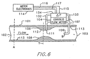
- Figure 6 discloses a bypass Coriolis flowmeter system similar to that of Figure 1. The difference is that in the system of Figure 6 the flowmeter inlet 106 is positioned downstream of outlet 111. In Figure 6, some of the material in conduit 101 will flow into inlet 106, through flowmeter 104 and outlet 111 back into the interior of the conduit. The material flows in that direction since the material pressure at inlet 106 is greater than that at outlet 111 due to the low pressure at the throat T of the venturi.
- a single differential pressure sensor 435 together with tubes 432 and 433 as shown on Figure 4 is not necessary and if desired, can be replaced with two separate pressure sensors 435A and 435B, one of which can be positioned at the terminus of tube 432 at material inlet 402. The other can be positioned at the terminus of tube 433 at material outlet 434.
- the signals from these two individual pressure gauges can then be applied over conductors 116A and 116B to meter electronics 114 (not shown on Figure 7) which can then operate in the same manner as described for Figures 4 and 5 for the use of a single differential pressure gauge 435 to derive material viscosity.
- Driver 417 and sensors 421, 423 on Figure 7 may be connected by conductors to meter electronics 114, 115 and 117 in the same manner as shown on Figure 5.
- a volumetric flowmeter having an inlet positioned shown, or element 106 in Figure 1, and having an outlet positioned proximate the throat T of a venturi may be advantageously subjected to an optimum pressure drop which will permit the flowmeter to operate in an optimum manner to determine the volume of the material flowing there through and in turn, the volume of the material flowing in the entirety of conduit 101.
- the same approach may be applied to different geometries and flow conditions where the specific equations may differ. But the method of determining the relevant material parameters and compensating for variations in the bypass ratio is still valid.
- bypass meters it is desirable to use bypass meters on large conduits conducting high rates of material flow.
- Existing bypass meters lack the high accuracy required of many applications because the bypass ratio varies with the material parameters.
- the preferred Coriolis flowmeters of the present invention enhance their accuracy without the penalty of permanent material pressure drop. This is achieved by use of a venturi to increase the portion of flow that goes through the Coriolis meter.
- the fluid dynamic equations associated with a venturi based bypass meter enable the bypass ratio to be calculated from the meter geometry and the fluid's relevant properties.
- the preferred Coriolis meters of the present invention continuously measure the relevant material properties and continuously calculate the bypass ratio and total mass flow rate.
Landscapes
- Physics & Mathematics (AREA)
- Fluid Mechanics (AREA)
- General Physics & Mathematics (AREA)
- Engineering & Computer Science (AREA)
- Manufacturing & Machinery (AREA)
- Measuring Volume Flow (AREA)
Claims (36)
- Durchflussmessvorrichtung zum Messen von Materialfluss in einer Leitung (101), wobei die Vorrichtung umfasst:einen Durchflussmesser (104; 400);einen Materialeinlass (106; 402), der einen Teil des Materialflusses in der Leitung zu dem Durchflussmesser ableitet, wobei der Materialeinlass in einem Innenraum der Leitung angeordnet und mit dem Durchflussmesser verbunden ist;einen Materialauslass (111; 434), der Material, das in dem Durchflussmesser fließt, zu der Leitung zurückführt, wobei der Materialauslass in dem Innenraum der Leitung angeordnet und mit dem Durchflussmesser verbunden ist;eine Einrichtung (108; 208; 400), die die Durchflussgeschwindigkeit des Materials in der Leitung an einer Leitungsposition in der Nähe des Materialauslasses zwischen dem Materialeinlass und dem Materialauslass erhöht; wobei der Materialauslass mit der Leitung an der Position mit einer erhöhten Durchflussgeschwindigkeit des Materials in der Leitung verbunden ist, um ein optimales Druckgefälle zwischen dem Materialeinlass und dem Materialauslass zu erzeugen und die Strömungsgeschwindigkeit des Materials in dem Durchflussmesser zu erhöhen;eine Einrichtung (114), die die Durchflussmenge und die Durchflussgeschwindigkeit sowie die Dichte des Materialflusses in dem Durchflussmesser bestimmt;eine Einrichtung (114), die auf das Bestimmen der Durchflussmenge und der Durchflussgeschwindigkeit sowie der Dichte des Materialflusses in dem Durchflussmesser anspricht und die Durchflussgeschwindigkeit sowie die Durchflussmenge des Materials in einem Abschnitt der Leitung zwischen dem Materialeinlass und dem Materialauslass bestimmt; undeine Einrichtung (114), die auf das Bestimmen der Durchflussmenge in dem Durchflussmesser und dem Leitungsabschnitt anspricht, um eine Gesamt-Durchflussmenge des Materials in der Leitung zu bestimmen.
- Vorrichtung nach Anspruch 1, wobei die Einrichtung, die die Durchflussgeschwindigkeit und die Durchflussmenge des Materials in dem Abschnitt der Leitung zwischen dem Materialeinlass und dem Materialauslass bestimmt, eine Einrichtung umfasst, die das Verhältnis der Durchflussgeschwindigkeit zwischen dem Material in dem Durchflussmesser und dem Material in dem Abschnitt der Leitung bestimmt.
- Vorrichtung nach Anspruch 1, die des Weiteren umfasst:eine Einrichtung (114, 134, 435), die die Viskosität des Materials in dem Durchflussmesser bestimmt;eine Einrichtung (114), die auf das Bestimmen der Viskosität und der Durchflussgeschwindigkeit sowie der Durchflussmenge und der Dichte des Materials anspricht und die Durchflussgeschwindigkeit sowie die Durchflussmenge des Materials in dem Abschnitt der Leitung bestimmt; undeine Einrichtung (114), die auf das Bestimmen der Durchflussgeschwindigkeit und der Durchflussmenge des Materials in dem Leitungsabschnitt anspricht und die Gesamt-Material-Durchflussmenge in der Leitung bestimmt.
- Vorrichtung nach Anspruch 3, wobei die Einrichtung, die die Durchflussgeschwindigkeit und die Durchflussmenge des Materials in dem Abschnitt der Leitung zwischen dem Materialeinlass und dem Materialauslass bestimmt, eine Einrichtung umfasst, die das Verhältnis der Durchflussgeschwindigkeit zwischen dem Material in dem Durchflussmesser und dem Material in dem Abschnitt der Leitung bestimmt.
- Vorrichtung nach Anspruch 1, wobei der Durchflussmesser einen Coriolis-Durchflussmesser umfasst.
- Vorrichtung nach Anspruch 5, wobei der Coriolis-Durchflussmesser des Weiteren umfasst:eine Druckerfassungseinrichtung (134, 435), die mit dem Materialeinlass und dem Materialauslass verbunden ist und eine Messung eines Materialdruckgefälles zwischen dem Materialeinlass und dem Materialauslass erzeugt; undeine Einrichtung (114), die auf die Messung des Materialdruckgefälles anspricht und eine Viskosität des Durchflussmaterials herleitet.
- Vorrichtung nach Anspruch 6, wobei die Einrichtung, die die Gesamt-Durchflussmenge des Materials in der Leitung bestimmt, umfasst:eine Einrichtung, die eine Durchflussgeschwindigkeit und eine Durchflussmenge des Materials in dem Durchflussmesser sowie eine Materialdichte und die Materialviskosität bestimmt; undeinen Einrichtung, die auf das Bestimmen der Durchflussgeschwindigkeit, der Durchflussmenge, der Dichte und der Viskosität des Materials in dem Durchflussmesser anspricht und die Durchflussmenge des Materials in dem Abschnitt der Leitung zwischen dem Materialeinlass und dem Materialauslass bestimmt.
- Vorrichtung nach Anspruch 1, wobei die Einrichtung, die auf das Bestimmen der Durchflussgeschwindigkeit und der Durchflussmenge sowie der Dichte des Materials in dem Durchflussmesser anspricht, die Durchflussgeschwindigkeit und die Durchflussmenge des Materials in dem Abschnitt der Leitung mit der erhöhten Durchflussgeschwindigkeit bestimmt.
- Vorrichtung nach Anspruch 8, wobei der Durchflussmesser einen Coriolis-Durchflussmesser umfasst.
- Vorrichtung nach Anspruch 9, wobei der Coriolis-Durchflussmesser des Weiteren umfasst:eine Druckerfassungseinrichtung (134, 435), die mit dem Materialeinlass und dem Materialauslass verbunden ist und eine Messung eines Materialdruckgefälles zwischen dem Materialeinlass und dem Materialauslass erzeugt; undeine Einrichtung (114), die auf die Messung des Materialdruckgefälles anspricht und eine Viskosität des Durchflussmaterials herleitet.
- Vorrichtung nach Anspruch 10, wobei die Einrichtung, die die Gesamt-Durchflussmenge des Materials in der Leitung bestimmt, umfasst:eine Einrichtung, die die Durchflussgeschwindigkeit und die Durchflussmenge und die Dichte sowie die Viskosität des Materials in dem Durchflussmesser bestimmt,eine Einrichtung, die auf das Bestimmen der Durchflussgeschwindigkeit, der Durchflussmenge, der Dichte und der Viskosität des Materials in dem Durchflussmesser anspricht und die Durchflussgeschwindigkeit sowie die Durchflussmenge des Materials in dem Leitungsabschnitt erhöhter Durchflussgeschwindigkeit bestimmt, undeine Einrichtung, die auf das Bestimmen der Durchflussgeschwindigkeit und der Durchflussmenge des Materials in dem Leitungsabschnitt anspricht und die Gesamt-Durchflussmenge des Materials in der Leitung bestimmt.
- Vorrichtung nach Anspruch 1, wobei der Materialauslass (111) stromauf von dem Materialeinlass (106) in der Leitung angeordnet ist.
- Vorrichtung nach Anspruch 1, wobei der Materialauslass (111; 434) stromab von dem Materialeinlass (106; 402) in der Leitung angeordnet ist.
- Vorrichtung nach Anspruch 1, wobei der Durchflussmesser ein volumetrischer Durchflussmesser ist.
- Vorrichtung nach Anspruch 1, wobei der Durchflussmesser ein Coriolis-Durchflussmesser ist; und
wobei die Einrichtung, die die Materialdurchflussgeschwindigkeit und die Durchflussmenge des Materials in dem Abschnitt der Leitung zwischen dem Materialeinlass und dem Materialauslass bestimmt, eine Einrichtung umfasst, die das Verhältnis der Strömungsgeschwindigkeit zwischen dem Material in dem Durchflussmesser und dem Material in dem Abschnitt der Leitung bestimmt. - Vorrichtung nach Anspruch 15, wobei der Coriolis-Durchflussmesser des Weiteren umfasst:eine Druckerfassungseinrichtung (134; 435), die mit dem Materialeinlass und dem Materialauslass verbunden ist und das Materialdruckgefälle zwischen dem Materialeinlass und dem Materialauslass misst; undeine Einrichtung (114), die auf die Messung des Materialdruckgefälles anspricht und die Viskosität des Durchflussmaterials herleitet.
- Vorrichtung nach Anspruch 15, wobei die Einrichtung, die die Durchflussgeschwindigkeit des Materials erhöht, eine Venturi-Düse (108; 208) umfasst, die im Inneren der Leitung angeordnet ist; und
wobei der Materialauslass (111) mit einem Verengungsbereich (T) der Venturi-Düse verbunden ist. - Vorrichtung nach Anspruch 15, wobei der Coriolis-Durchflussmesser (104) außerhalb der Leitung angeordnet ist.
- Vorrichtung nach Anspruch 17, wobei die Venturi-Düse (108) an der Innenfläche (113) der Leitung befestigt ist.
- Vorrichtung nach Anspruch 17, wobei die Venturi-Düse (208) und der Verengungsbereich von den Innenflächen (113) der Leitung beabstandet sind.
- Vorrichtung nach Anspruch 13, wobei der Coriolis-Durchflussmesser (400) im Inneren der Leitung angeordnet ist.
- Vorrichtung nach Anspruch 21, wobei der Coriolis-Durchflussmesser umfasst:einen länglichen Körper (401), der im Inneren der Leitung angeordnet ist, wobei der Körper und die Leitung parallele Längsachsen haben;ein stromaufliegendes Ende des Körpers, das den Materialeinlass (402) aufweist, der Material aufnimmt, das durch den Coriolis-Durchflussmesser zu leiten ist;einen stromabliegenden Endabschnitt des Körpers, der den Materialauslass (434) aufweist, der Material aus dem Körper wieder in das Innere der Leitung abgibt;ein Paar paralleler Durchflusskanäle (409, 411) in dem Körper, die Längsachsen parallel zur Längsachse des Körpers aufweisen;eine Einrichtung (414, 415), die den stromabliegenden Endabschnitt der Durchflusskanäle mit dem stromabliegenden Endabschnitt des Körpers verbindet;eine Einrichtung (412, 413), die den stromaufliegenden Endabschnitt der Durchflusskanäle mit dem stromaufliegenden Endabschnitt des Körpers verbindet;wobei Material, das in den Einlass des Körpers eintritt, durch die Durchflusskanäle und den Auslass des Körpers geleitet und zu dem Material zurückgeführt wird, das in der Leitung fließt;eine Einrichtung (417), die die Kanäle in Quer- und in Längsrichtung zueinander in Schwingung versetzt; undeine Einrichtung, die Sensoreinrichtungen (421, 423) enthält, die mit den Durchflusskanälen verbunden sind und auf die Schwingung ansprechen, wenn Material durch die Durchflusskanäle fließt, um die Gesamt-Materialströmungsmenge in der Leitung herzuleiten.
- Vorrichtung nach Anspruch 22, wobei der stromabliegende Endabschnitt des Körpers (401) eine Venturi-Düse umfasst, und wobei der Auslass (434) des Körpers in der Nähe der Verengung (T) der Venturi-Düse angeordnet ist.
- Vorrichtung nach Anspruch 23, wobei der Coriolis-Durchflussmesser des Weiteren umfasst:eine Druckerfassungseinrichtung (435), die mit dem Materialeinlass (402) und dem Materialauslass (434) verbunden ist und das Materialdruckgefälle zwischen dem Einlass und dem Auslass misst;eine Einrichtung (114), die auf die Messung des Materialdruckgefälles anspricht und die Viskosität des Durchflussmaterials herleitet; undeine Einrichtung (114), die auf das Herleiten der Viskosität anspricht und die Durchflussgeschwindigkeit sowie die Durchflussmenge des Materials in der Venturi-Düse und dann die Gesamt-Durchflussmenge des Materials in der Leitung bestimmt.
- Verfahren zum Messen von Materialfluss in einer Leitung, wobei das Verfahren die folgenden Schritte umfasst:Ableiten eines Teils des Materialflusses in einer Leitung zu einem Durchflussmesser mit einem Materialeinlass, der in einem Innenraum der Leitung angeordnet und mit dem Durchflussmesser verbunden ist;Zurückführen von Material, das in dem Durchflussmesser fließt, zu der Leitung über einen Materialauslass, der in dem Innenraum der Leitung angeordnet und mit dem Durchflussmesser verbunden ist;Erhöhen der Durchflussgeschwindigkeit und der Durchflussmenge des Materials in einem Leitungsabschnitt in der Nähe des Materialauslasses;Verbinden des Materialauslasses mit der Leitung an der Position mit einer erhöhten Durchflussgeschwindigkeit und Durchflussmenge, um ein optimales Druckgefälle zwischen dem Materialeinlass und dem Materialauslass des Durchflussmessers zu erzeugen und den Materialfluss innerhalb des Durchflussmessers zu erhöhen;Bestimmen der Durchflussgeschwindigkeit und der Durchflussmenge sowie der Dichte des Materials in dem Durchflussmesser;Bestimmen der Durchflussgeschwindigkeit und der Durchflussmenge des Materials in einem Abschnitt der Leitung zwischen dem Materialeinlass und dem Materialauslass in Reaktion auf das Bestimmen der Durchflussgeschwindigkeit und der Durchflussmenge sowie der Dichte des Materials in dem Durchflussmesser; undBestimmen einer Gesamt-Durchflussmenge des Materials in der Leitung in Reaktion auf das Bestimmen der Durchflussgeschwindigkeit und der Durchflussmenge des Materials in dem Durchflussmesser und des Materials in dem Leitungsabschnitt.
- Verfahren nach Anspruch 24, wobei der Durchflussmesser einen Coriolis-Durchflussmesser umfasst.
- Verfahren nach Anspruch 25, das die folgenden Schritte einschließt:Verbinden einer Druckerfassungseinrichtung mit dem Materialeinlass und dem Materialauslass, um eine Messung eines Materialdruckgefälles zwischen dem Materialeinlass und dem Materialauslass zu erzeugen; undHerleiten einer Viskosität des Durchflussmaterials in Reaktion auf die Messung des Materialdruckgefälles.
- Verfahren nach Anspruch 27, das die folgenden Schritte einschließt:Bestimmen der Durchflussgeschwindigkeit und der Durchflussmenge sowie der Dichte und der Viskosität des Materials in dem Durchflussmesser;Bestimmen der Durchflussgeschwindigkeit und der Durchflussmenge des Materials in dem Leitungsabschnitt in Reaktion auf das Bestimmen der Durchflussgeschwindigkeit, der Durchflussmenge, der Dichte und der Viskosität des Materials in dem Durchflussmesser; undBestimmen der Gesamt-Durchflussmenge des Materials in der Leitung.
- Verfahren nach Anspruch 25, wobei der Durchflussmesser ein Coriolis-Durchflussmesser ist; und
wobei der Schritt des Bestimmens der Durchflussgeschwindigkeit und der Durchflussmenge des Materials in dem Abschnitt der Leitung zwischen dem Materialeinlass und dem Materialauslass einen Schritt des Bestimmens des Verhältnisses der Durchflussgeschwindigkeit zwischen dem Material in dem Durchflussmesser und dem Material in dem Abschnitt der Leitung umfasst. - Verfahren nach Anspruch 26, das die folgenden Schritte einschließt:Messen eines Materialdruckgefälles zwischen dem Materialeinlass und dem Materialauslass; undHerleiten einer Viskosität des Durchflussmaterials in Reaktion auf die Messung des Materialdruckgefälles.
- Verfahren nach Anspruch 30, das die folgenden Schritte einschließt:Bestimmen der Durchflussgeschwindigkeit und der Durchflussmenge sowie der Dichte und der Viskosität des Materials in dem Durchflussmesser;Bestimmen der Durchflussgeschwindigkeit und der Durchflussmenge des Materials in dem Leitungsabschnitt mit erhöhter Durchflussgeschwindigkeit in Reaktion auf das Bestimmen der Durchflussgeschwindigkeit, der Durchflussmenge, der Dichte und der Viskosität des Materials in dem Durchflussmesser; undBestimmen der Gesamt-Durchflussmenge des Materials in der Leitung in Reaktion auf das Bestimmen der Durchflussgeschwindigkeit und der Durchflussmenge des Materials in dem Durchflussmesser und des Materials in dem Leitungsabschnitt.
- Verfahren nach Anspruch 25, das den Schritt einschließt, bei dem die erhöhte Durchflussgeschwindigkeit erzielt wird, indem der Materialauslass in der Nähe einer Verengung einer Venturi-Düse angeordnet wird.
- Verfahren nach Anspruch 32, wobei das Verfahren des Weiteren die folgenden Schritte umfasst:Betätigen einer Drucksensoreinrichtung, die mit dem Durchflussmesser verbunden ist, um das Materialdruckgefälle zwischen dem Materialeinlass und dem Materialauslass des Durchflussmessers zu messen; undHerleiten der Viskosität des Materialflusses in der Leitung in Reaktion auf das Herleiten des Materialdruckgefälles.
- Verfahren nach Anspruch 25, das die folgenden Schritte einschließt:Positionieren eines länglichen Körpers eines Coriolis-Durchflussmessers im Inneren der Leitung, wobei der Körper und die Leitung parallele Längsachsen aufweisen;Leiten von Material, das von einem stromaufliegenden Endabschnitt des Körpers mit dem Materialeinlass aufgenommen wird, durch den Corioiis-Durchflussmesser; Ablassen von Material aus dem Körper zurück in den Innenraum der Leitung über einen stromabliegenden Endabschnitt des Körpers mit dem Materialauslass;wobei ein Paar paralleler Durchflusskanäle in dem Körper Längsachsen parallel zu den Längsachsen des Körpers haben;Verbinden der stromabliegenden Enden der Strömungskanäle mit dem stromabliegenden Endabschnitt des Körpers;Verbinden der stromaufliegenden Endabschnitte der Strömungskanäle mit dem stromaufliegenden Endabschnitt des Körpers;wobei Material, das in den Materialeinlass des Körpers eintritt, durch die Strömungskanäle und den Materialauslass des Körpers geleitet und zu dem Material zurückgeführt wird, das in der Leitung fließt;Versetzen der Strömungskanäle in Schwingung quer zueinander, undBetätigen einer Sensoreinrichtung, die auf die Schwingung anspricht, während Material durch die Kanäle fließt, um Informationen bezüglich des Materialflusses in der Leitung herzuleiten.
- Verfahren nach Anspruch 34, das die folgenden Schritte einschließt:Anordnen des Materialauslasses des Körpers in der Nähe einer Verengung einer Venturi-Düse, die durch den Körper gebildet wird.
- Verfahren nach Anspruch 35, das die folgenden Schritte einschließt:Betätigen einer Drucksensoreinrichtung, die mit dem Körper verbunden ist, um das Materialdruckgefälle zwischen dem Materialeinlass und dem Auslass des Durchflussmesserkörpers zu messen;Herleiten der Viskosität des Materialflusses in dem Durchflussmesser in Reaktion auf das Herleiten des Materialdruckgefälles; undHerleiten der Gesamt-Durchflussmenge des Materials in der Leitung in Reaktion auf das Herleiten der Viskosität.
Applications Claiming Priority (3)
| Application Number | Priority Date | Filing Date | Title |
|---|---|---|---|
| US58755096A | 1996-01-17 | 1996-01-17 | |
| US587550 | 1996-01-17 | ||
| PCT/US1997/000633 WO1997026509A1 (en) | 1996-01-17 | 1997-01-16 | Bypass type coriolis effect flowmeter |
Publications (2)
| Publication Number | Publication Date |
|---|---|
| EP0874976A1 EP0874976A1 (de) | 1998-11-04 |
| EP0874976B1 true EP0874976B1 (de) | 2002-04-10 |
Family
ID=24350243
Family Applications (1)
| Application Number | Title | Priority Date | Filing Date |
|---|---|---|---|
| EP97902034A Expired - Lifetime EP0874976B1 (de) | 1996-01-17 | 1997-01-16 | Bypass-durchflussmesser |
Country Status (12)
| Country | Link |
|---|---|
| US (1) | US5861561A (de) |
| EP (1) | EP0874976B1 (de) |
| JP (1) | JP3283524B2 (de) |
| KR (1) | KR100328273B1 (de) |
| CN (1) | CN1134651C (de) |
| AU (1) | AU1579797A (de) |
| BR (1) | BR9706984A (de) |
| CA (1) | CA2241934C (de) |
| DE (1) | DE69711846T2 (de) |
| MX (1) | MX9805699A (de) |
| RU (1) | RU2181477C2 (de) |
| WO (1) | WO1997026509A1 (de) |
Families Citing this family (120)
| Publication number | Priority date | Publication date | Assignee | Title |
|---|---|---|---|---|
| US5661232A (en) | 1996-03-06 | 1997-08-26 | Micro Motion, Inc. | Coriolis viscometer using parallel connected Coriolis mass flowmeters |
| US6253624B1 (en) | 1998-01-13 | 2001-07-03 | Rosemount Inc. | Friction flowmeter |
| US6151557A (en) * | 1998-01-13 | 2000-11-21 | Rosemount Inc. | Friction flowmeter with improved software |
| US6575927B1 (en) | 1998-09-25 | 2003-06-10 | The Regents Of The University Of Michigan | System and method for determining blood flow rate in a vessel |
| ATE235672T1 (de) * | 1998-12-11 | 2003-04-15 | Flowtec Ag | Coriolis-massedurchfluss-/dichtemesser |
| TW421710B (en) * | 1999-04-13 | 2001-02-11 | Inst Of Nuclear Energy Res Roc | Method and device for bi-directional low-velocity flow measurement |
| US6494105B1 (en) * | 1999-05-07 | 2002-12-17 | James E. Gallagher | Method for determining flow velocity in a channel |
| US6308553B1 (en) * | 1999-06-04 | 2001-10-30 | Honeywell International Inc | Self-normalizing flow sensor and method for the same |
| US6609431B1 (en) | 2000-09-29 | 2003-08-26 | Xellogy, Inc. | Flow measuring device based on predetermine class of liquid |
| FR2823191B1 (fr) * | 2001-04-06 | 2003-09-05 | Tokheim Services France | Procede de controle de la teneur en hydrocarbures d'une vapeur circulant dans une installation equipee d'un systeme d'aspiration de vapeur |
| US6856251B1 (en) | 2001-04-26 | 2005-02-15 | Xsilogy, Inc. | Systems and methods for sensing pressure |
| US6992590B1 (en) | 2001-04-27 | 2006-01-31 | Xsilogy, Inc. | Systems and methods for sensing a fluid supply status |
| US6636815B2 (en) * | 2001-08-29 | 2003-10-21 | Micro Motion, Inc. | Majority component proportion determination of a fluid using a coriolis flowmeter |
| US7111491B2 (en) * | 2001-09-08 | 2006-09-26 | Ashcroft Inc. | Portable differential pressure generator |
| US20040206154A1 (en) * | 2002-05-16 | 2004-10-21 | Kosh William Stephen | Portable differential pressure generator |
| GB2373058B (en) * | 2001-09-18 | 2003-02-19 | Tayside Flow Technologies Ltd | Spiral flow testing |
| US20030098069A1 (en) | 2001-11-26 | 2003-05-29 | Sund Wesley E. | High purity fluid delivery system |
| JP3845615B2 (ja) * | 2002-03-12 | 2006-11-15 | アドバンス電気工業株式会社 | 流量センサー |
| US7011180B2 (en) * | 2002-09-18 | 2006-03-14 | Savant Measurement Corporation | System for filtering ultrasonic noise within a fluid flow system |
| CH696006A5 (de) | 2002-12-23 | 2006-11-15 | Sensirion Ag | Vorrichtung zur Messung des Flusses eines Gases oder einer Flüssigkeit in einem Nebenkanal. |
| US6868741B2 (en) * | 2003-03-05 | 2005-03-22 | Veris, Inc. | Device and method enabling fluid characteristic measurement utilizing fluid acceleration |
| WO2005010467A2 (en) * | 2003-07-24 | 2005-02-03 | Fti Flow Technology, Inc. | Vibrating tube mass flow meter |
| GB2406386B (en) * | 2003-09-29 | 2007-03-07 | Schlumberger Holdings | Isokinetic sampling |
| US20050267413A1 (en) * | 2004-05-26 | 2005-12-01 | Wang Jong H | Flow monitoring devices and methods of use |
| US7000463B1 (en) | 2004-11-12 | 2006-02-21 | Mks Instruments, Inc. | Reynolds number correction function for mass flow rate sensor |
| DE102005014058B4 (de) * | 2004-11-23 | 2010-04-08 | Krohne Ag | Verfahren zum Betreiben eines Massendurchflußmeßgeräts |
| JP2006153677A (ja) * | 2004-11-30 | 2006-06-15 | Dainippon Screen Mfg Co Ltd | 差圧式流量計、流量制御装置および基板処理装置 |
| CA2587175C (en) * | 2004-11-30 | 2013-02-26 | Micro Motion, Inc. | Method and apparatus for determining flow pressure using density information |
| JP4437744B2 (ja) * | 2004-12-27 | 2010-03-24 | 大日本スクリーン製造株式会社 | 液体供給装置、基板処理装置および液体供給方法 |
| US7228735B2 (en) * | 2005-02-03 | 2007-06-12 | Integrated Sensing Systems, Inc. | Fluid sensing device with integrated bypass and process therefor |
| KR20140063884A (ko) * | 2005-03-29 | 2014-05-27 | 마이크로 모우션, 인코포레이티드 | 유체의 특성을 결정하기 위한 방법 및 코리올리 유량계 |
| JP4944882B2 (ja) * | 2005-06-29 | 2012-06-06 | マイクロ・モーション・インコーポレーテッド | 多成分流内の1つの成分の密度を測定するための方法及び装置 |
| DE102005046319A1 (de) | 2005-09-27 | 2007-03-29 | Endress + Hauser Flowtec Ag | Verfahren zum Messen eines in einer Rohrleitung strömenden Mediums sowie Meßsystem dafür |
| GB2432425B (en) * | 2005-11-22 | 2008-01-09 | Schlumberger Holdings | Isokinetic sampling method and system for multiphase flow from subterranean wells |
| US7617055B2 (en) * | 2006-08-28 | 2009-11-10 | Invensys Systems, Inc. | Wet gas measurement |
| US7636640B2 (en) * | 2006-09-05 | 2009-12-22 | Brooks Instrument, Llc | Multi-gas flow device |
| DE102006062600B4 (de) | 2006-12-29 | 2023-12-21 | Endress + Hauser Flowtec Ag | Verfahren zum Inbetriebnehmen und/oder Überwachen eines In-Line-Meßgeräts |
| RU2431821C2 (ru) * | 2007-03-14 | 2011-10-20 | Майкро Моушн, Инк. | Измеритель вибрирующего потока и способ для определения вязкости материала потока |
| GB2447908B (en) * | 2007-03-27 | 2009-06-03 | Schlumberger Holdings | System and method for spot check analysis or spot sampling of a multiphase mixture flowing in a pipeline |
| US7845688B2 (en) * | 2007-04-04 | 2010-12-07 | Savant Measurement Corporation | Multiple material piping component |
| US8855948B2 (en) * | 2007-04-20 | 2014-10-07 | Invensys Systems, Inc. | Wet gas measurement |
| US8892371B2 (en) * | 2007-04-20 | 2014-11-18 | Invensys Systems, Inc. | Wet gas measurement |
| CN101109686B (zh) * | 2007-08-16 | 2011-01-19 | 西安东风机电有限公司 | 一种对通过管道的流体粘度进行检测的方法 |
| US8215157B2 (en) * | 2007-10-04 | 2012-07-10 | Baxter International Inc. | System and method for measuring liquid viscosity in a fluid delivery system |
| US20090093774A1 (en) * | 2007-10-04 | 2009-04-09 | Baxter International Inc. | Ambulatory pump with intelligent flow control |
| US7730793B2 (en) * | 2007-11-16 | 2010-06-08 | Honeywell International Inc. | Venturi flow sensor |
| US7654157B2 (en) * | 2007-11-30 | 2010-02-02 | Honeywell International Inc. | Airflow sensor with pitot tube for pressure drop reduction |
| US7810401B2 (en) * | 2008-03-07 | 2010-10-12 | Cameron International Corporation | Apparatus and method for operation in the laminar, transition, and turbulent flow regimes |
| DE102008016235A1 (de) | 2008-03-27 | 2009-10-01 | Endress + Hauser Flowtec Ag | Verfahren zum Betreiben eines auf einer rotierenden Karussell-Abfüllmachine angeordneten Meßgeräts |
| KR101572011B1 (ko) | 2008-05-01 | 2015-11-26 | 마이크로 모우션, 인코포레이티드 | 유량계 파라미터에서의 이상을 검출하기 위한 방법 |
| DE102008002217A1 (de) * | 2008-06-04 | 2009-12-10 | Endress + Hauser Flowtec Ag | Vorrichtung zur Bestimmung und/oder Überwachung eines Strömungsparameters |
| US8104340B2 (en) * | 2008-12-19 | 2012-01-31 | Honeywell International Inc. | Flow sensing device including a tapered flow channel |
| WO2010111355A1 (en) * | 2009-03-24 | 2010-09-30 | Norcross Corporation | In-line viscometer with no moving parts and methods and computer-readable media for maintaining a desired viscosity |
| WO2011068500A1 (en) * | 2009-12-01 | 2011-06-09 | Micro Motion, Inc. | Vibratory flowmeter friction compensation |
| US20110138929A1 (en) * | 2009-12-10 | 2011-06-16 | Malema Engineering Corporation | Kinetic Flow Meter |
| US8453646B2 (en) * | 2009-12-22 | 2013-06-04 | Honeywell International Inc. | Sensor apparatus and method to regulate air flow in a powered air purifying respirator |
| DE102010000761A1 (de) | 2010-01-11 | 2011-07-28 | Endress + Hauser Flowtec Ag | Meßsystem mit einem Meßwandler vom Vibrationstyp |
| DE102010000759B4 (de) | 2010-01-11 | 2025-05-22 | Endress + Hauser Flowtec Ag | Meßsystem mit einem Meßwandler vom Vibrationstyp |
| CN102686985B (zh) | 2009-12-31 | 2015-04-01 | 恩德斯+豪斯流量技术股份有限公司 | 具有振动型测量转换器的测量系统 |
| CA2785919C (en) | 2009-12-31 | 2016-05-24 | Endress+Hauser Flowtec Ag | Measuring system having a measuring transducer of vibration-type |
| EP2519804B1 (de) * | 2009-12-31 | 2019-08-28 | Endress+Hauser Flowtec AG | Mess-system mit einem messwandler vom vibrationstyp |
| DE102010000760B4 (de) | 2010-01-11 | 2021-12-23 | Endress + Hauser Flowtec Ag | Meßsystem mit einem Meßwandler vom Vibrationstyp zum Messen eines statischen Drucks in einem strömenden Medium |
| DE102010000755B4 (de) * | 2010-01-08 | 2018-12-13 | Endress+Hauser Flowtec Ag | Anordnung zur Messung der Viskosität einer gleichmäßig temperierten Flüssigkeit |
| US8397586B2 (en) * | 2010-03-22 | 2013-03-19 | Honeywell International Inc. | Flow sensor assembly with porous insert |
| US8113046B2 (en) | 2010-03-22 | 2012-02-14 | Honeywell International Inc. | Sensor assembly with hydrophobic filter |
| US8656772B2 (en) | 2010-03-22 | 2014-02-25 | Honeywell International Inc. | Flow sensor with pressure output signal |
| US8756990B2 (en) | 2010-04-09 | 2014-06-24 | Honeywell International Inc. | Molded flow restrictor |
| US20140136125A1 (en) * | 2010-05-04 | 2014-05-15 | Agar Corporation Ltd. | System and method for multi-phase fluid measurement |
| US9003877B2 (en) | 2010-06-15 | 2015-04-14 | Honeywell International Inc. | Flow sensor assembly |
| US8418549B2 (en) | 2011-01-31 | 2013-04-16 | Honeywell International Inc. | Flow sensor assembly with integral bypass channel |
| DE102010039543A1 (de) | 2010-08-19 | 2012-02-23 | Endress + Hauser Flowtec Ag | Meßsystem mit einem Meßwandler vom Vibrationstyp |
| GB2483671B (en) * | 2010-09-15 | 2016-04-13 | Managed Pressure Operations | Drilling system |
| GB2499943A (en) * | 2010-11-08 | 2013-09-04 | Mezurx Pty Ltd | Re-calibration of instruments |
| GB2499167B (en) * | 2010-11-08 | 2018-01-10 | Mezurx Pty Ltd | Flow measurement |
| DE102010044179A1 (de) | 2010-11-11 | 2012-05-16 | Endress + Hauser Flowtec Ag | Meßsystem mit einem Meßwandler von Vibrationstyp |
| US8695417B2 (en) | 2011-01-31 | 2014-04-15 | Honeywell International Inc. | Flow sensor with enhanced flow range capability |
| FR2973828B1 (fr) * | 2011-04-11 | 2014-04-18 | Snf Sas | Ensemble de materiel de mesure et regulation de viscosite en ligne a haute pression |
| GB2490685B (en) | 2011-05-10 | 2017-05-24 | Salunda Ltd | Fluid conduit |
| ITPD20110148A1 (it) * | 2011-05-12 | 2012-11-13 | Metersit Srl | Contatore per gas, particolarmente per portate elevate |
| WO2013126043A1 (en) * | 2012-02-21 | 2013-08-29 | Halliburton Energy Services, Inc. | A pressure differential flow meter including a constriction device that can create multiple areas of constriction |
| GB2499995B (en) * | 2012-03-05 | 2018-01-31 | Spirax-Sarco Ltd | Flow meter |
| EP2825853A1 (de) * | 2012-03-13 | 2015-01-21 | Micro Motion, Inc. | Indirekter massenstromsensor |
| JP6218840B2 (ja) | 2012-09-27 | 2017-10-25 | マイクロ モーション インコーポレイテッド | 参照温度における流動流体粘度を取得するメータ電子機器及び方法 |
| US9052217B2 (en) | 2012-11-09 | 2015-06-09 | Honeywell International Inc. | Variable scale sensor |
| NL2010798C2 (nl) * | 2013-05-14 | 2014-11-24 | Berkin Bv | Stromingsmeetapparaat voor het meten van een stroming van een medium. |
| US9080908B2 (en) * | 2013-07-24 | 2015-07-14 | Jesse Yoder | Flowmeter design for large diameter pipes |
| NL2012126C2 (en) * | 2014-01-23 | 2015-07-29 | Berkin Bv | Flow measurement system and method for determining at least one property of a medium. |
| US20160161307A1 (en) | 2014-12-05 | 2016-06-09 | General Electric Company | System and method for metering gas |
| US10760934B2 (en) | 2014-12-05 | 2020-09-01 | Natural Gas Solutions North America, Llc | Using localized flow characteristics on electronic flow meter to quantify volumetric flow |
| CN105010095B (zh) * | 2015-07-06 | 2017-05-17 | 河海大学 | 一种比流量式灌溉水量计量控制装置 |
| US9952079B2 (en) | 2015-07-15 | 2018-04-24 | Honeywell International Inc. | Flow sensor |
| EP3199925A1 (de) * | 2016-02-01 | 2017-08-02 | Proces-Data A/S | Vorrichtung und verfahren zur massendurchflussmessung |
| CN105602627B (zh) * | 2016-03-16 | 2018-10-02 | 华东理工大学 | 流量分配装置 |
| US10648842B2 (en) | 2016-06-22 | 2020-05-12 | Benoit & Cote Inc. | Fluid flow measuring and control devices and method |
| US11988064B2 (en) | 2016-12-12 | 2024-05-21 | Weatherford Technology Holdings, Llc | Managed pressure drilling control system with continuously variable transmission |
| US10520344B2 (en) * | 2017-04-20 | 2019-12-31 | Itron, Inc. | Proportional flow comparative metering |
| US20200222647A1 (en) * | 2017-07-07 | 2020-07-16 | The Johns Hopkins University | Barotrauma and volutrauma prevention device |
| US10544674B2 (en) | 2017-08-23 | 2020-01-28 | Saudi Arabian Oil Company | Multiphase flow meter with tuning fork |
| CN107727541B (zh) * | 2017-10-31 | 2023-08-08 | 中国石油大学(北京) | 管道内气溶胶监测装置及方法以及管道系统 |
| DE102017130781A1 (de) * | 2017-12-20 | 2019-06-27 | Truedyne Sensors AG | Verfahren zum Bestimmen eines Volumen- und/oder Massendurchflusses |
| US10598527B2 (en) * | 2018-01-29 | 2020-03-24 | Weatherford Technology Holdings, Llc | Differential flow measurement with Coriolis flowmeter |
| CN108333312A (zh) * | 2018-03-12 | 2018-07-27 | 上海重塑能源科技有限公司 | 尾排氢气浓度检测装置及燃料电池车辆 |
| DE102018205502A1 (de) * | 2018-04-11 | 2019-10-17 | E.G.O. Elektro-Gerätebau GmbH | Sensorvorrichtung und Verfahren zur Untersuchung einer Flüssigkeit und Waschmaschine |
| GB2581745B (en) * | 2018-09-13 | 2020-11-25 | M Flow Tech Ltd | Mass flow rate calculation method |
| DE102018122427A1 (de) * | 2018-09-13 | 2020-03-19 | Truedyne Sensors AG | Adapter zum fluidischen Anbinden |
| GB2572836B (en) * | 2018-09-13 | 2020-09-02 | M-Flow Tech Ltd | Void fraction calibration method |
| KR102046035B1 (ko) * | 2018-09-18 | 2019-11-18 | 주식회사 삼천리 | 가스 미터용 장애 진단 장치 및 이를 이용한 가스 미터 |
| CN113167624A (zh) * | 2018-09-27 | 2021-07-23 | C.I.B.优尼瓦斯股份公司 | 用于测量燃料流量的模块和包括这种模块的燃烧器 |
| DE102018126230A1 (de) * | 2018-10-22 | 2020-04-23 | Truedyne Sensors AG | Verfahren zum Verifizieren eines Dichte- und/oder Viskositätsmessgerätes in einer Messstelle |
| US12520778B2 (en) | 2019-10-23 | 2026-01-13 | Larry C. Sarver | Flow valve system with flow sensor, fluid valve, and radio module |
| US11307068B2 (en) * | 2019-10-23 | 2022-04-19 | Larry C. Sarver | Flow valve system with ultrasonic flow sensor |
| DE102019134804A1 (de) * | 2019-12-17 | 2021-06-17 | Reseatech Gmbh | Messanordnung mit einem mikromechanischen Sensor zum Erfassen von Eigenschaften eines strömenden Fluids |
| DE112021003296A5 (de) | 2020-06-18 | 2023-05-11 | Endress+Hauser Flowtec Ag | Vibronisches Meßsystem |
| DE102020122596A1 (de) | 2020-08-28 | 2022-03-03 | Ifm Electronic Gmbh | Messvorrichtung zur Strömungsmessung in einem Rohr |
| DE102020131649A1 (de) | 2020-09-03 | 2022-03-03 | Endress + Hauser Flowtec Ag | Vibronisches Meßsystem |
| EP3974785A1 (de) | 2020-09-23 | 2022-03-30 | Heinrichs Messtechnik GmbH | Coriolis-durchflussmessgerät sowie verfahren zum betrieb des coriolis-durchflussmessgeräts |
| RO135767A2 (ro) * | 2020-11-24 | 2022-05-30 | Horia Mihai Motit | Debitmetru cu reacţie fără piese mobile cu configuraţie individuală în by-pass şi respectiv extinsă şi metodă de măsurare a debitului în baza acestuia |
| US12669023B2 (en) | 2021-08-02 | 2026-06-30 | Weatherford Technology Holdings, Llc | Real time flow rate and rheology measurement |
| US11661805B2 (en) | 2021-08-02 | 2023-05-30 | Weatherford Technology Holdings, Llc | Real time flow rate and rheology measurement |
| CN119096118A (zh) * | 2022-04-12 | 2024-12-06 | 高准有限公司 | 流体流动参数的压力补偿 |
Family Cites Families (9)
| Publication number | Priority date | Publication date | Assignee | Title |
|---|---|---|---|---|
| US3314290A (en) * | 1965-07-26 | 1967-04-18 | Technion Res & Dev Foundation | Shunt flow meter |
| JPS6045806B2 (ja) * | 1979-08-22 | 1985-10-12 | 株式会社日立製作所 | 発熱抵抗体を用いた空気流量計 |
| US5497665A (en) * | 1991-02-05 | 1996-03-12 | Direct Measurement Corporation | Coriolis mass flow rate meter having adjustable pressure and density sensitivity |
| US5226728A (en) * | 1991-11-04 | 1993-07-13 | Badger Meter, Inc. | Method and apparatus for measuring mass flow and energy content using a differential pressure meter |
| CA2086962A1 (en) * | 1992-01-21 | 1993-07-22 | Dee J. Neville | Sidestream flow sensor for spirometry |
| US5333496A (en) * | 1992-03-09 | 1994-08-02 | Fenelon Paul J | In-line parallel proportionally partitioned by-pass metering device and method |
| DE69314780T2 (de) * | 1992-03-20 | 1998-04-16 | Micro Motion Inc | Verbesserter viskosimeter für sanitäre anwendungen |
| US5347874A (en) | 1993-01-25 | 1994-09-20 | Micro Motion, Incorporated | In-flow coriolis effect mass flowmeter |
| US5297426A (en) * | 1993-04-07 | 1994-03-29 | Abb K-Flow Inc. | Hydrodynamic fluid divider for fluid measuring devices |
-
1997
- 1997-01-16 BR BR9706984A patent/BR9706984A/pt not_active IP Right Cessation
- 1997-01-16 RU RU98115286/28A patent/RU2181477C2/ru active
- 1997-01-16 JP JP52614997A patent/JP3283524B2/ja not_active Expired - Lifetime
- 1997-01-16 DE DE69711846T patent/DE69711846T2/de not_active Expired - Lifetime
- 1997-01-16 CA CA002241934A patent/CA2241934C/en not_active Expired - Lifetime
- 1997-01-16 EP EP97902034A patent/EP0874976B1/de not_active Expired - Lifetime
- 1997-01-16 AU AU15797/97A patent/AU1579797A/en not_active Abandoned
- 1997-01-16 KR KR1019980705501A patent/KR100328273B1/ko not_active Expired - Lifetime
- 1997-01-16 WO PCT/US1997/000633 patent/WO1997026509A1/en not_active Ceased
- 1997-01-16 CN CNB971928851A patent/CN1134651C/zh not_active Expired - Lifetime
- 1997-02-25 US US08/805,474 patent/US5861561A/en not_active Expired - Lifetime
-
1998
- 1998-07-15 MX MX9805699A patent/MX9805699A/es unknown
Also Published As
| Publication number | Publication date |
|---|---|
| MX9805699A (es) | 1998-11-30 |
| JP2000502453A (ja) | 2000-02-29 |
| US5861561A (en) | 1999-01-19 |
| WO1997026509A1 (en) | 1997-07-24 |
| CA2241934A1 (en) | 1997-07-24 |
| BR9706984A (pt) | 1999-07-20 |
| KR100328273B1 (ko) | 2002-09-26 |
| DE69711846T2 (de) | 2002-08-29 |
| KR19990077354A (ko) | 1999-10-25 |
| RU2181477C2 (ru) | 2002-04-20 |
| CN1134651C (zh) | 2004-01-14 |
| DE69711846D1 (de) | 2002-05-16 |
| AU1579797A (en) | 1997-08-11 |
| JP3283524B2 (ja) | 2002-05-20 |
| CN1213431A (zh) | 1999-04-07 |
| HK1018810A1 (en) | 2000-01-07 |
| CA2241934C (en) | 2002-08-06 |
| EP0874976A1 (de) | 1998-11-04 |
Similar Documents
| Publication | Publication Date | Title |
|---|---|---|
| US5861561A (en) | Bypass type coriolis effect flowmeter | |
| US11852517B2 (en) | Method for generating a diagnostic from a deviation of a flow meter parameter | |
| US5661232A (en) | Coriolis viscometer using parallel connected Coriolis mass flowmeters | |
| US6550345B1 (en) | Technique for measurement of gas and liquid flow velocities, and liquid holdup in a pipe with stratified flow | |
| US6907361B2 (en) | Ultrasonic flow-measuring method | |
| US6957586B2 (en) | System to measure density, specific gravity, and flow rate of fluids, meter, and related methods | |
| US20020078737A1 (en) | Detection of liquid in gas pipeline | |
| NO169310B (no) | Stroemningsmaaler samt fremgangsmaate for maaling av en tofase fluid-volumstroem | |
| NO20171056A1 (en) | Ultrasonic viscometer | |
| CN101523165A (zh) | 用于流量计中几何热补偿的仪表电子和方法 | |
| AU2011239253B2 (en) | Method for Generating a Diagnostic from a Deviation of a Flow Meter Parameter | |
| AU2011239256A1 (en) | Method for Generating a Diagnostic from a Deviation of a Flow Meter Parameter | |
| JPH10111159A (ja) | 湧出し式質量流量計 | |
| HK1018810B (en) | Bypass type flowmeter |
Legal Events
| Date | Code | Title | Description |
|---|---|---|---|
| PUAI | Public reference made under article 153(3) epc to a published international application that has entered the european phase |
Free format text: ORIGINAL CODE: 0009012 |
|
| 17P | Request for examination filed |
Effective date: 19980702 |
|
| AK | Designated contracting states |
Kind code of ref document: A1 Designated state(s): CH DE FR GB LI |
|
| GRAG | Despatch of communication of intention to grant |
Free format text: ORIGINAL CODE: EPIDOS AGRA |
|
| RTI1 | Title (correction) |
Free format text: BYPASS TYPE FLOWMETER |
|
| 17Q | First examination report despatched |
Effective date: 20010816 |
|
| GRAG | Despatch of communication of intention to grant |
Free format text: ORIGINAL CODE: EPIDOS AGRA |
|
| GRAH | Despatch of communication of intention to grant a patent |
Free format text: ORIGINAL CODE: EPIDOS IGRA |
|
| GRAH | Despatch of communication of intention to grant a patent |
Free format text: ORIGINAL CODE: EPIDOS IGRA |
|
| REG | Reference to a national code |
Ref country code: GB Ref legal event code: IF02 |
|
| GRAA | (expected) grant |
Free format text: ORIGINAL CODE: 0009210 |
|
| AK | Designated contracting states |
Kind code of ref document: B1 Designated state(s): CH DE FR GB LI |
|
| REG | Reference to a national code |
Ref country code: CH Ref legal event code: EP |
|
| REG | Reference to a national code |
Ref country code: CH Ref legal event code: NV Representative=s name: TROESCH SCHEIDEGGER WERNER AG |
|
| REF | Corresponds to: |
Ref document number: 69711846 Country of ref document: DE Date of ref document: 20020516 |
|
| ET | Fr: translation filed | ||
| PLBE | No opposition filed within time limit |
Free format text: ORIGINAL CODE: 0009261 |
|
| STAA | Information on the status of an ep patent application or granted ep patent |
Free format text: STATUS: NO OPPOSITION FILED WITHIN TIME LIMIT |
|
| 26N | No opposition filed |
Effective date: 20030113 |
|
| REG | Reference to a national code |
Ref country code: FR Ref legal event code: PLFP Year of fee payment: 20 |
|
| PGFP | Annual fee paid to national office [announced via postgrant information from national office to epo] |
Ref country code: DE Payment date: 20160127 Year of fee payment: 20 Ref country code: CH Payment date: 20160127 Year of fee payment: 20 |
|
| PGFP | Annual fee paid to national office [announced via postgrant information from national office to epo] |
Ref country code: FR Payment date: 20160126 Year of fee payment: 20 Ref country code: GB Payment date: 20160127 Year of fee payment: 20 |
|
| REG | Reference to a national code |
Ref country code: DE Ref legal event code: R071 Ref document number: 69711846 Country of ref document: DE |
|
| REG | Reference to a national code |
Ref country code: CH Ref legal event code: PL |
|
| REG | Reference to a national code |
Ref country code: GB Ref legal event code: PE20 Expiry date: 20170115 |
|
| PG25 | Lapsed in a contracting state [announced via postgrant information from national office to epo] |
Ref country code: GB Free format text: LAPSE BECAUSE OF EXPIRATION OF PROTECTION Effective date: 20170115 |