EP0875135A2 - Ventilateur pour transporter des matériaux à forte usure - Google Patents
Ventilateur pour transporter des matériaux à forte usure Download PDFInfo
- Publication number
- EP0875135A2 EP0875135A2 EP98106051A EP98106051A EP0875135A2 EP 0875135 A2 EP0875135 A2 EP 0875135A2 EP 98106051 A EP98106051 A EP 98106051A EP 98106051 A EP98106051 A EP 98106051A EP 0875135 A2 EP0875135 A2 EP 0875135A2
- Authority
- EP
- European Patent Office
- Prior art keywords
- blower
- wing
- fan impeller
- housing
- blower according
- Prior art date
- Legal status (The legal status is an assumption and is not a legal conclusion. Google has not performed a legal analysis and makes no representation as to the accuracy of the status listed.)
- Granted
Links
- 239000000463 material Substances 0.000 title claims abstract description 80
- 230000003628 erosive effect Effects 0.000 title 1
- 239000010902 straw Substances 0.000 claims description 5
- 239000008187 granular material Substances 0.000 abstract 1
- 239000000843 powder Substances 0.000 abstract 1
- 230000015572 biosynthetic process Effects 0.000 description 5
- 238000005755 formation reaction Methods 0.000 description 5
- 230000000694 effects Effects 0.000 description 4
- 235000008733 Citrus aurantifolia Nutrition 0.000 description 3
- 235000011941 Tilia x europaea Nutrition 0.000 description 3
- 238000007664 blowing Methods 0.000 description 3
- 239000004571 lime Substances 0.000 description 3
- 239000003082 abrasive agent Substances 0.000 description 2
- 239000003337 fertilizer Substances 0.000 description 2
- 239000002245 particle Substances 0.000 description 2
- 230000001737 promoting effect Effects 0.000 description 2
- 230000001681 protective effect Effects 0.000 description 2
- 230000005540 biological transmission Effects 0.000 description 1
- 239000013590 bulk material Substances 0.000 description 1
- 239000011248 coating agent Substances 0.000 description 1
- 238000000576 coating method Methods 0.000 description 1
- 230000008021 deposition Effects 0.000 description 1
- 238000007599 discharging Methods 0.000 description 1
- 238000005265 energy consumption Methods 0.000 description 1
- 230000014759 maintenance of location Effects 0.000 description 1
- 238000005259 measurement Methods 0.000 description 1
- 239000002362 mulch Substances 0.000 description 1
- 239000000725 suspension Substances 0.000 description 1
- 238000011144 upstream manufacturing Methods 0.000 description 1
- 239000002023 wood Substances 0.000 description 1
Images




Classifications
-
- A—HUMAN NECESSITIES
- A01—AGRICULTURE; FORESTRY; ANIMAL HUSBANDRY; HUNTING; TRAPPING; FISHING
- A01M—CATCHING, TRAPPING OR SCARING OF ANIMALS; APPARATUS FOR THE DESTRUCTION OF NOXIOUS ANIMALS OR NOXIOUS PLANTS
- A01M9/00—Special adaptations or arrangements of powder-spraying apparatus for purposes covered by this subclass
- A01M9/0007—Pneumatic dusters
- A01M9/003—Pneumatic field dusters, e.g. self-propelled, drawn or tractor-mounted
-
- A—HUMAN NECESSITIES
- A01—AGRICULTURE; FORESTRY; ANIMAL HUSBANDRY; HUNTING; TRAPPING; FISHING
- A01C—PLANTING; SOWING; FERTILISING
- A01C15/00—Fertiliser distributors
- A01C15/04—Fertiliser distributors using blowers
Definitions
- the invention relates to a blower for conveying very abrasive Blown materials, especially for the pneumatic application of straw or Bulk goods, with at least one vane conveyor wheel, which in one Fan housing rotates.
- DE 33 22 969 A1 is already a mobile forest limescale device known that a blower of the type mentioned for liming large forest stands.
- the previously known blower has Wing feed wheel that rotates in a blower housing.
- the wings the wing conveyor wheel are bent backwards, so that a moist lime is evenly spread and spread over the surface can be.
- the ejection channel of the known fan pivoted and can be from the cab or can be swiveled automatically to ensure an even coating of the floor even when the vehicle is moving slowly.
- blowers for example in agriculture used for the pneumatic conveying of straw and bulk materials there is a problem in that these blown materials have a high have an abrasive effect, so that the fan and the rotating inside Wing conveyor wheel are subject to high wear. This applies especially when a swiveling ejection channel is provided that controls the flow of blow material at least in some areas Way is put. A targeted blowing out of the blow material flow is required, however, to ensure an even spreading of the Blown material can also be reached over long distances.
- the solution of this task according to the invention consists in the blower of the type mentioned in particular in that the wing feed wheel on the leading walls of its wings and / or that the blower housing in at least one of the blown material Part of its housing inner wall retaining profiles or Holding recesses to form a blown material cushion exhibit.
- the blower according to the invention points in the area of the blow material applied parts, namely on the leading walls of the wing and / or retaining profiles or on the inner wall of the housing Retention wells, which are during the operation of the invention Blower with the blow material so that it Blower parts are covered with a protective material pad. After the formation of this material cushion, the relevant parts come with the blow material flowing into the blower no longer directly in contact and are therefore against the abrasive effect of this abrasive material well protected. Depending on the dimensions and the Density of the blown material conveyed can hold wells required or holding profiles with a for example sawtooth-like profile cross section should be sufficient. By means of the Holding profiles or holding depressions provided according to the invention is also used with a powerful blower Excessive wear from the blow material transported in the blower avoided.
- the holding recesses for example on the wings of the vane conveyor wheel can form at the leading Wing walls and / or on the housing inner wall approximately parallel to Fins or ribs oriented on the axis of rotation of the impeller be provided which limit the holding depressions between them. It is advantageous if the holding recesses also on their End faces oriented transversely to the longitudinal direction of the web have, through appropriate crosspieces or through the rear wall of the wing conveyor wheel can be formed.
- the webs or ribs should be at a distance be arranged from 10 to 100 mm and a height of 10 to 40 mm to have.
- the holding depressions in the region of the outlet channel of the blower compared to that on the inner circumference of the blower housing arranged holding recesses have smaller clear dimensions and if necessary those provided in the area of the outlet duct Bridges or ribs at relatively smaller intervals are arranged from each other.
- At least one Fan impeller is provided, which is preferably on the blower housing a separate and in particular central air inlet is assigned.
- the fan impeller also turns away from the blades Side of the conveyor wheel rear wall generates an air flow that one Flow short circuit and an overflow of the conveyor wheel rear wall counteracts by the blow material flow.
- the wing feed wheel and at least one fan impeller have a common shaft and that the air and material inlet assigned to the vane conveyor wheel on the one hand and the air inlet of the at least one fan impeller on the other hand, on opposite end faces of the fan housing are arranged.
- An undesirable overflow of the conveyor wheel rear wall through the Blow material flow can be effectively counteracted and at the same time the delivery rate of the blower according to the invention is significantly increased be, if at least one fan impeller is provided that as Pressure fan impeller is formed.
- vane conveyor wheel and the neighboring one Fan impeller have a common rear or side wall.
- this preferred embodiment forms the feed wheel rear wall at the same time the side wall of the neighboring fan impeller.
- a particularly dense and correspondingly heavy blow material To be able to apply over long distances, it is advantageous if between the outer fan impeller and the impeller Pressure fan impeller is provided. It is also on the Overflow from the side of the pressure fan impeller facing away from the blades of the blow material flow effectively prevented if there is another Fan impeller is provided, the blades of which are the blades of the blade feed wheel essentially correspond. Continuing education according to the invention therefore provides that the wings of an outer Fan impeller the wings of the wing conveyor wheel essentially correspond and that between the outer fan impeller and Wing conveyor wheel preferably provided a pressure fan impeller is.
- the air and material outlet of the blower housing has a rectangular opening cross section. While a material outlet with a round cross section, the flow velocities unified in the airflow generated by the blower, can the inhomogeneous air flow through an in Flow freely through the cross-section of the rectangular material outlet, which is essential for a uniform delivery of the blow material accommodates.
- blower parts in the way according to the invention that the fan housing relative to one Fan carrier around an approximately horizontally oriented axis of rotation is rotatable and that the air and material outlet of the blower in the use position, preferably transversely to the direction of travel Fan associated tractor or the like vehicle is aligned.
- the vertical ejection direction of the radial fan to the Adjust the slope Since the entire blower housing with the Airflow outlet horizontally relative to a fan bracket oriented axis of rotation is adjustable and not just the airflow outlet This adjustment is adjusted separately via redirections to the terrain formation with no changes to the specific data connected to the blower according to the invention.
- the invention Blower is characterized in particular in this embodiment an unchanged high performance in every position of the blower housing. Despite its difficult Terrain formations high work performance can the invention Blowers can be operated comparatively inexpensively.
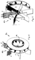
- blower housing 3 of a radial blower is shown. As is indicated in FIG. 2, the blower housing 3 also has the portion of its housing inner wall acted upon by the blow material corresponding holding depressions 2.
- the on the housing inner wall and / or on the leading wing walls provided recesses 2 are by webs or ribs 4th limited, which is approximately parallel to the axis of rotation of the vane conveyor wheel 101, 103, 104, 106 run. These are on the wing conveyor wheel 101, 103, 104, 106 provided recesses also on their End faces oriented transversely to the axis of rotation are closed educated. While the holding recesses 2 on one End face essentially limited by the rear wall 5 of the feed wheel are on the opposite, the air and material inlet front side of the blower facing the blower or ribs 6 provided.
- the webs provided on the wings and on the inside of the housing or ribs 4, 6 are approximately at a distance of 10 to 100 mm arranged and have a height of 10 to 40 mm.
- Fig. 3 to 7 shown versions on the wing 1 facing away Side of the wing conveyor wheel 101, 103, 104 and 106 at least one Fan impeller 8, 8a provided, which has its own central air inlet is assigned to the blower housing 3.
- Fig. 7 it is shown that the air inlet 9 of the at least one fan impeller 8a and Air and material inlet 10 of the wing conveyor wheel 104 opposite sides of the blower housing are arranged. How 3 to 7 also show the wing feed wheel 103, 104 or 106 and the at least one fan impeller 8, 8a common shaft 11 on.
- the wings of the fan impeller 8 essentially the blades 1 of the blade feed wheel 103 correspond, as is the case, for example, in FIG. 3 is shown. There are also on the blades of the fan impeller 8 holding depressions 2 are provided.
- fan impeller In the case of heavier blow material, however, it is possible to use the fan impeller to design as a pressure fan impeller 8a in order to carry out the Blow goods to provide a larger air flow rate can.
- fan impellers designed as a pressure fan impeller 8a are the wing feed wheels 104 and 106 in FIG. 4 assigned to 6.
- the conveyor wheel rear wall 5 also forms in the 4 and 5 embodiment shown the back or Side wall of the fan impeller, so that a powerful and nevertheless very compact impeller design is possible.
- the pressure fan impeller 8a is also on it the wing conveyor wheel 104 side facing apart from a central Inlet opening 12 executed closed.
- FIG. 6 an embodiment is shown, which in particular dense, possibly moist and correspondingly heavy blow material can be used advantageously.
- the embodiment shown in Fig. 6 corresponds essentially to the double impeller shown in FIG. 3, however, is between the outer fan impeller 8 and the vane impeller 106 an additional pressure fan impeller 8a is provided. Because the diameter of a blower impeller regularly increases promotional blowing material is to adjust the diameter of the Pressure fan impeller 8a smaller than the diameter of the neighboring one Fan impeller and blade conveyor wheels 8, 106.
- the vanes 1 of the vane conveyor wheel 106 and the vanes of the outer fan impeller 8 over the outer circumference of the rear or Side walls in front.
- the pressure fan impeller 8a makes a strong one Airflow generated, the free wing ends in particular Wing conveyor wheel 106 overflows. That over the material cushion flowing blow material is coming from the pressure fan impeller 8a Airflow raised and accelerated so that even heavy Blow material particles and large quantities of blow material far from the radial fan can be carried out.
- Fig. 6 Design and arrangement of the fan impellers 8, 8a as well as the vane conveyor wheel 106 with the provided on one end face and for Pressure fan impeller 8a leading inlet opening 12 becomes a early and optimal mixing of the blow and conveyed goods reached.
- the rectangular shape shown in FIG. 2 bears the outlet opening provided on the spiral housing 3 to an optimal Spreading material distribution significantly.
- the provided on the wing conveyor wheels 101, 103, 104 and 106 Holding depressions 2 fill depending on the material to be blown as well as the flow conditions inside the fan except for one certain height. This is due to the abrasive blow material Deposition always even and an imbalance of the vane conveyor wheel 101, 103, 104, 106 cannot occur. An imbalance of the vane conveyor wheel is also avoided in that the, approximately in the same Distances from the axis of rotation arranged holding recesses 2 of the individual wings 1 have approximately the same receiving volume.
- the measurements of the holding recesses on the inside of the housing Spiral housing 3 and on the wings or blades of the wing conveyor wheels 101, 103, 104 and 106 depend on the nature of the conveyed good.
- blowers shown can be used, for example, in agriculture for conveying sawdust, mulch or wood chips or for Spreading lime and fertilizers can be used.
- the special design of these radial fans allows one powerful operation with low energy consumption.
- a fan 13 is shown that in his Spiral or blower housing 3 with a wing conveyor wheel 104 has additional pressure fan impeller 8a.
- the blower 13 is arranged on a mobile blower carrier 14 which with a Tractor or similar tractor is connected.
- the blower 13 can also be designed as a vehicle body and on a Loading truck of a vehicle arranged and / or fixed to the vehicle be mountable. It is also possible to use the blower support to design that this on the three-point suspension of the Tractor is releasably attachable.
- the outlet channel 7 is included the outlet opening in the use position transverse to the direction of travel Tractor or similar vehicle aligned.
- the blower 13 is associated with an adjustment device between the blower carrier 14 and the blower housing 2 is effective.
- a hydraulic actuator 18 By means of the Adjustment device, preferably a hydraulic actuator 18 has, the vertical ejection direction of the radial fan 13 adjust. Since the entire blower housing 3 with the Outlet opening relative to the fan bracket 14 by a horizontal oriented rotation axis, the fan 13 for example, be adapted to the terrain formation without associated with a change in the specific data of the blower would. Rather, the blower 13 stands out in any position its blower housing 2 practically unchanged due to a high Performance. Despite the even in difficult terrain formations high performance of the blower 13 can this comparatively can be operated inexpensively and practically without wear.
- Fig. 7 it can be seen that the air and material inlet 10 of the Blower 13 a reservoir 15 for the blown material to be discharged is connected upstream. Between the air and material inlet 10 and a supply device is provided to the reservoir 15 here is designed as a conveyor belt 16 and a hydraulic Has conveyor drive.
- the wing conveyor wheel 104 and the associated pressure fan impeller 8a are on a common, approximately horizontally oriented Rotor shaft 11 arranged. This is contrary to the direction of travel protruding end of the rotor shaft 11 with a belt transmission 19 or the same reduction gear in drive connection, the Gearbox input with a drive motor or preferably with the PTO of the tractor is connected. In the same way you can also the hydraulic cylinder 18 of the adjusting device and the Conveyor drive of the feed device 16 via the PTO Tractor to be driven.
Landscapes
- Life Sciences & Earth Sciences (AREA)
- Environmental Sciences (AREA)
- Soil Sciences (AREA)
- Engineering & Computer Science (AREA)
- Insects & Arthropods (AREA)
- Pest Control & Pesticides (AREA)
- Wood Science & Technology (AREA)
- Zoology (AREA)
- Structures Of Non-Positive Displacement Pumps (AREA)
- Constituent Portions Of Griding Lathes, Driving, Sensing And Control (AREA)
- Physical Or Chemical Processes And Apparatus (AREA)
- Manufacturing Of Micro-Capsules (AREA)
- Nozzles (AREA)
- Air Transport Of Granular Materials (AREA)
- Grinding-Machine Dressing And Accessory Apparatuses (AREA)
- Filling Or Emptying Of Bunkers, Hoppers, And Tanks (AREA)
Applications Claiming Priority (2)
| Application Number | Priority Date | Filing Date | Title |
|---|---|---|---|
| DE29706042U DE29706042U1 (de) | 1997-04-05 | 1997-04-05 | Vorrichtung zum Ausbringen feinkörnigen oder pulverigen Materials |
| DE29706042U | 1997-04-05 |
Publications (3)
| Publication Number | Publication Date |
|---|---|
| EP0875135A2 true EP0875135A2 (fr) | 1998-11-04 |
| EP0875135A3 EP0875135A3 (fr) | 1999-03-24 |
| EP0875135B1 EP0875135B1 (fr) | 2002-08-14 |
Family
ID=8038478
Family Applications (1)
| Application Number | Title | Priority Date | Filing Date |
|---|---|---|---|
| EP98106051A Expired - Lifetime EP0875135B1 (fr) | 1997-04-05 | 1998-04-02 | Ventilateur pour transporter des matériaux à forte usure |
Country Status (3)
| Country | Link |
|---|---|
| EP (1) | EP0875135B1 (fr) |
| AT (1) | ATE222050T1 (fr) |
| DE (2) | DE29706042U1 (fr) |
Cited By (3)
| Publication number | Priority date | Publication date | Assignee | Title |
|---|---|---|---|---|
| DE10120131C1 (de) * | 2001-04-25 | 2002-09-12 | Winand Wolf | Auskleidungselement für einen Förderweg |
| EP1709869A1 (fr) | 2005-04-09 | 2006-10-11 | Maschinenfabrik Bernard van Lengerich GmbH & Co. | Dispositif à mélanger et distribuer des produits en vrac |
| EP3623635A1 (fr) | 2018-09-17 | 2020-03-18 | Technische Universität Dresden | Transporteur pour copeaux et autres produits en vrac |
Families Citing this family (1)
| Publication number | Priority date | Publication date | Assignee | Title |
|---|---|---|---|---|
| DE202007011167U1 (de) | 2007-08-09 | 2007-10-11 | Schneider, Rudi | Ausblaseinrichtung |
Citations (1)
| Publication number | Priority date | Publication date | Assignee | Title |
|---|---|---|---|---|
| DE3322969A1 (de) | 1983-06-25 | 1985-01-03 | Johannes 3530 Warburg Peine | Fahrbares waldkalkgeraet |
Family Cites Families (7)
| Publication number | Priority date | Publication date | Assignee | Title |
|---|---|---|---|---|
| US1753936A (en) * | 1926-06-17 | 1930-04-08 | Westinghouse Electric & Mfg Co | Blower for powdered fuel |
| US1806494A (en) * | 1928-02-23 | 1931-05-19 | James D O'brien | Protective lining |
| US3608976A (en) * | 1969-09-12 | 1971-09-28 | Fines A Zugelder | Fan blade having wear-resistant ribs and fan including a plurality of same |
| CH634796A5 (en) * | 1979-01-04 | 1983-02-28 | Lanker Ag | Pneumatic conveying device, especially for hay, straw and cereals |
| FR2476434A1 (fr) * | 1980-02-26 | 1981-08-28 | Deere John Cie Francaise | Ventilateur pour machine de recolte |
| DE3544629C1 (de) * | 1985-12-17 | 1986-11-13 | Mathias 7450 Hechingen Hirlinger | Pneumatische Fördervorrichtung mit einem Gebläse zum Fördern von Schüttgut, insbesondere Heu, Stroh, Körnern oder anderem landwirtschaftlichen Gut |
| DE4340237A1 (de) * | 1993-11-25 | 1995-06-01 | Amazonen Werke Dreyer H | Schleuderdüngerstreuer |
-
1997
- 1997-04-05 DE DE29706042U patent/DE29706042U1/de not_active Expired - Lifetime
-
1998
- 1998-04-02 EP EP98106051A patent/EP0875135B1/fr not_active Expired - Lifetime
- 1998-04-02 DE DE59805150T patent/DE59805150D1/de not_active Expired - Lifetime
- 1998-04-02 AT AT98106051T patent/ATE222050T1/de active
Patent Citations (1)
| Publication number | Priority date | Publication date | Assignee | Title |
|---|---|---|---|---|
| DE3322969A1 (de) | 1983-06-25 | 1985-01-03 | Johannes 3530 Warburg Peine | Fahrbares waldkalkgeraet |
Cited By (4)
| Publication number | Priority date | Publication date | Assignee | Title |
|---|---|---|---|---|
| DE10120131C1 (de) * | 2001-04-25 | 2002-09-12 | Winand Wolf | Auskleidungselement für einen Förderweg |
| EP1253092A1 (fr) | 2001-04-25 | 2002-10-30 | Winand Wolf | Elément de revêtement pour un chemin de transport |
| EP1709869A1 (fr) | 2005-04-09 | 2006-10-11 | Maschinenfabrik Bernard van Lengerich GmbH & Co. | Dispositif à mélanger et distribuer des produits en vrac |
| EP3623635A1 (fr) | 2018-09-17 | 2020-03-18 | Technische Universität Dresden | Transporteur pour copeaux et autres produits en vrac |
Also Published As
| Publication number | Publication date |
|---|---|
| DE59805150D1 (de) | 2002-09-19 |
| ATE222050T1 (de) | 2002-08-15 |
| EP0875135A3 (fr) | 1999-03-24 |
| DE29706042U1 (de) | 1997-06-19 |
| EP0875135B1 (fr) | 2002-08-14 |
Similar Documents
| Publication | Publication Date | Title |
|---|---|---|
| DE6930657U (de) | Vorrichtung zum verteilen oder ausstreuen pulveriger oder gekoernter stoffe | |
| DE2954169C2 (fr) | ||
| DE1407674A1 (de) | Einrichtung zum Ausbreiten oder Ausstreuen irgendeines Stoffes oder Materials | |
| EP3927138B1 (fr) | Dispositif de dosage pour matériel granulaire et machine de distribution avec dispositif de dosage | |
| EP0875135B1 (fr) | Ventilateur pour transporter des matériaux à forte usure | |
| EP1707042B1 (fr) | Distributeur centrifuge à deux disques pour des matériaux granulaires, en particulier engrais, sel ou similaires | |
| AT407327B (de) | Strohhäcksler für einen mähdrescher | |
| EP0559242B1 (fr) | Expandeur centrifuge | |
| CH633599A5 (de) | Salz- und/oder sand-streugeraet. | |
| DE202014010611U1 (de) | Schwenkbarer Anbau-Streustoffverteiler in Modulbauweise | |
| EP0427935A1 (fr) | Procédé à l'usage d'un epandeur d'engrais centrifuge | |
| DE1940922C3 (de) | Kunstdüngerstreuer | |
| EP1247437A2 (fr) | Procédé de distribution des matériaux à épandre et engin de distribution à distributeur centrifuge pour mettre ledit procédé en oeuvre | |
| DE19946851A1 (de) | Düngerstreuer | |
| EP2092124B1 (fr) | Dispositif d'épandage à monter sur un véhicule de support | |
| WO2015055699A1 (fr) | Dispositif de déversement de granulés | |
| DE69914039T2 (de) | Verteilmaschine | |
| DE19733549B4 (de) | Zweischeiben-Schleuderstreuer | |
| EP1836888A1 (fr) | Epandeur centrifuge pour engrais | |
| DE8710411U1 (de) | Fahrbare Streuvorrichtung für trockenes oder nasses Streugut, insbesondere Mist | |
| DE3627141A1 (de) | Streuvorrichtung an einem kraftfahrzeug | |
| DE2209197A1 (de) | Zentrifugalstreuer | |
| DE202025100275U1 (de) | Scheibenstreuer mit einem Auslaufschacht | |
| DE9416478U1 (de) | Vorrichtung zum Verteilen von Mulch im Gelände | |
| EP1184517A2 (fr) | Appareil de répandage pour service d'hiver et disque d'épandage pour celui-ci |
Legal Events
| Date | Code | Title | Description |
|---|---|---|---|
| PUAI | Public reference made under article 153(3) epc to a published international application that has entered the european phase |
Free format text: ORIGINAL CODE: 0009012 |
|
| AK | Designated contracting states |
Kind code of ref document: A2 Designated state(s): AT CH DE FR LI NL |
|
| AX | Request for extension of the european patent |
Free format text: AL;LT;LV;MK;RO;SI |
|
| PUAL | Search report despatched |
Free format text: ORIGINAL CODE: 0009013 |
|
| AK | Designated contracting states |
Kind code of ref document: A3 Designated state(s): AT BE CH DE DK ES FI FR GB GR IE IT LI LU MC NL PT SE |
|
| AX | Request for extension of the european patent |
Free format text: AL;LT;LV;MK;RO;SI |
|
| 17P | Request for examination filed |
Effective date: 19990304 |
|
| AKX | Designation fees paid |
Free format text: AT CH DE FR LI NL |
|
| 17Q | First examination report despatched |
Effective date: 20010625 |
|
| GRAG | Despatch of communication of intention to grant |
Free format text: ORIGINAL CODE: EPIDOS AGRA |
|
| GRAG | Despatch of communication of intention to grant |
Free format text: ORIGINAL CODE: EPIDOS AGRA |
|
| GRAH | Despatch of communication of intention to grant a patent |
Free format text: ORIGINAL CODE: EPIDOS IGRA |
|
| GRAA | (expected) grant |
Free format text: ORIGINAL CODE: 0009210 |
|
| GRAH | Despatch of communication of intention to grant a patent |
Free format text: ORIGINAL CODE: EPIDOS IGRA |
|
| AK | Designated contracting states |
Kind code of ref document: B1 Designated state(s): AT CH DE FR LI NL |
|
| PG25 | Lapsed in a contracting state [announced via postgrant information from national office to epo] |
Ref country code: NL Free format text: LAPSE BECAUSE OF FAILURE TO SUBMIT A TRANSLATION OF THE DESCRIPTION OR TO PAY THE FEE WITHIN THE PRESCRIBED TIME-LIMIT Effective date: 20020814 |
|
| REF | Corresponds to: |
Ref document number: 222050 Country of ref document: AT Date of ref document: 20020815 Kind code of ref document: T |
|
| REG | Reference to a national code |
Ref country code: CH Ref legal event code: EP |
|
| REF | Corresponds to: |
Ref document number: 59805150 Country of ref document: DE Date of ref document: 20020919 |
|
| REG | Reference to a national code |
Ref country code: CH Ref legal event code: NV Representative=s name: HANS RUDOLF GACHNANG PATENTANWALT |
|
| NLV1 | Nl: lapsed or annulled due to failure to fulfill the requirements of art. 29p and 29m of the patents act | ||
| ET | Fr: translation filed | ||
| PLBE | No opposition filed within time limit |
Free format text: ORIGINAL CODE: 0009261 |
|
| STAA | Information on the status of an ep patent application or granted ep patent |
Free format text: STATUS: NO OPPOSITION FILED WITHIN TIME LIMIT |
|
| 26N | No opposition filed |
Effective date: 20030515 |
|
| PGFP | Annual fee paid to national office [announced via postgrant information from national office to epo] |
Ref country code: DE Payment date: 20100406 Year of fee payment: 13 |
|
| PGFP | Annual fee paid to national office [announced via postgrant information from national office to epo] |
Ref country code: FR Payment date: 20110315 Year of fee payment: 14 |
|
| PGFP | Annual fee paid to national office [announced via postgrant information from national office to epo] |
Ref country code: CH Payment date: 20110408 Year of fee payment: 14 |
|
| PGFP | Annual fee paid to national office [announced via postgrant information from national office to epo] |
Ref country code: AT Payment date: 20110429 Year of fee payment: 14 |
|
| REG | Reference to a national code |
Ref country code: DE Ref legal event code: R119 Ref document number: 59805150 Country of ref document: DE |
|
| REG | Reference to a national code |
Ref country code: DE Ref legal event code: R119 Ref document number: 59805150 Country of ref document: DE |
|
| REG | Reference to a national code |
Ref country code: CH Ref legal event code: PL |
|
| REG | Reference to a national code |
Ref country code: AT Ref legal event code: MM01 Ref document number: 222050 Country of ref document: AT Kind code of ref document: T Effective date: 20120402 |
|
| REG | Reference to a national code |
Ref country code: FR Ref legal event code: ST Effective date: 20121228 |
|
| PG25 | Lapsed in a contracting state [announced via postgrant information from national office to epo] |
Ref country code: LI Free format text: LAPSE BECAUSE OF NON-PAYMENT OF DUE FEES Effective date: 20120430 Ref country code: CH Free format text: LAPSE BECAUSE OF NON-PAYMENT OF DUE FEES Effective date: 20120430 Ref country code: AT Free format text: LAPSE BECAUSE OF NON-PAYMENT OF DUE FEES Effective date: 20120402 |
|
| PG25 | Lapsed in a contracting state [announced via postgrant information from national office to epo] |
Ref country code: FR Free format text: LAPSE BECAUSE OF NON-PAYMENT OF DUE FEES Effective date: 20120430 |
|
| PG25 | Lapsed in a contracting state [announced via postgrant information from national office to epo] |
Ref country code: DE Free format text: LAPSE BECAUSE OF NON-PAYMENT OF DUE FEES Effective date: 20111031 |