EP0875191A1 - Pied mélangeur et méthode pour monter un pied mélangeur - Google Patents
Pied mélangeur et méthode pour monter un pied mélangeur Download PDFInfo
- Publication number
- EP0875191A1 EP0875191A1 EP98105379A EP98105379A EP0875191A1 EP 0875191 A1 EP0875191 A1 EP 0875191A1 EP 98105379 A EP98105379 A EP 98105379A EP 98105379 A EP98105379 A EP 98105379A EP 0875191 A1 EP0875191 A1 EP 0875191A1
- Authority
- EP
- European Patent Office
- Prior art keywords
- housing
- electric motor
- motor unit
- coupling
- hand blender
- Prior art date
- Legal status (The legal status is an assumption and is not a legal conclusion. Google has not performed a legal analysis and makes no representation as to the accuracy of the status listed.)
- Granted
Links
- 238000000034 method Methods 0.000 title claims description 7
- 230000008878 coupling Effects 0.000 claims description 42
- 238000010168 coupling process Methods 0.000 claims description 42
- 238000005859 coupling reaction Methods 0.000 claims description 42
- 238000003466 welding Methods 0.000 claims description 4
- 238000007789 sealing Methods 0.000 claims 2
- 238000004519 manufacturing process Methods 0.000 description 6
- 239000004033 plastic Substances 0.000 description 3
- 238000004026 adhesive bonding Methods 0.000 description 2
- 238000003860 storage Methods 0.000 description 2
- OKTJSMMVPCPJKN-UHFFFAOYSA-N Carbon Chemical compound [C] OKTJSMMVPCPJKN-UHFFFAOYSA-N 0.000 description 1
- 239000004952 Polyamide Substances 0.000 description 1
- 239000004743 Polypropylene Substances 0.000 description 1
- 230000005540 biological transmission Effects 0.000 description 1
- 229910052799 carbon Inorganic materials 0.000 description 1
- 239000003365 glass fiber Substances 0.000 description 1
- 239000007788 liquid Substances 0.000 description 1
- 239000002184 metal Substances 0.000 description 1
- 230000002093 peripheral effect Effects 0.000 description 1
- 229920002647 polyamide Polymers 0.000 description 1
- -1 polypropylene Polymers 0.000 description 1
- 229920001155 polypropylene Polymers 0.000 description 1
- 238000003825 pressing Methods 0.000 description 1
- 238000010079 rubber tapping Methods 0.000 description 1
Images


Classifications
-
- A—HUMAN NECESSITIES
- A47—FURNITURE; DOMESTIC ARTICLES OR APPLIANCES; COFFEE MILLS; SPICE MILLS; SUCTION CLEANERS IN GENERAL
- A47J—KITCHEN EQUIPMENT; COFFEE MILLS; SPICE MILLS; APPARATUS FOR MAKING BEVERAGES
- A47J43/00—Implements for preparing or holding food, not provided for in other groups of this subclass
- A47J43/04—Machines for domestic use not covered elsewhere, e.g. for grinding, mixing, stirring, kneading, emulsifying, whipping or beating foodstuffs, e.g. power-driven
- A47J43/07—Parts or details, e.g. mixing tools, whipping tools
- A47J43/08—Driving mechanisms
Definitions
- the present invention relates to a hand blender with an electric motor unit, which in a housing is received and a method for its assembly.
- Such a hand blender is already known from DE 37 09 573.
- a Housing provided that is integrally connected to a blender, and in the Cavity an electric motor unit is added.
- the one with a casing provided electric motor unit is to be driven on the blender Device facing end connected to a drive coupling and over an elastic ring element with an angular cross section is mounted on the housing.
- At the axially opposite end of the electric motor unit there is a plastic bearing part in contact with this axial end of the electric motor unit, which has connections to the housing wall for lateral and axial fixation of the electric motor unit.
- the electric motor unit on End of the hand blender is essentially rigidly connected to the housing and at the other axial end is mounted elastically on the housing, both the electric motor unit as well as the parts that connect them to the housing within narrow manufacturing tolerances getting produced.
- the production effort is additionally through increased a relatively high assembly and manufacturing costs for bearing parts.
- the device to be driven e.g. a blender, averted Section of the electric motor unit and the jacket area of the electric motor unit freely suspended in the hand blender housing.
- the electric motor unit exclusively in a foremost, that is, facing the device to be driven Section firmly connected to the housing, causing vibration transmissions from Electric motor on the housing are structurally easy to prevent, and a heat insulating Air gap between the casing of the electric motor unit and the Inner wall of the hand blender housing is given.
- the electric motor unit is on the Housing attached by means of a snap or snap connection. This is a simplified one Assembly possible by plugging both parts together.
- This locking connection is advantageously between a motor coupling, the Part of the housing of the electric motor unit on the device to be driven is facing end, and a housing coupling that is part of the housing of the Hand blender is formed at the end facing the device to be driven.
- a single ring seal is provided around the interior of the housing to seal between the electric motor unit and the housing.
- the snap or snap connection is such arranged that the ring seal when a snap or snap connection is engaged is compressed.
- this is a relatively tight fit of the electric motor unit in the housing and on the other hand compensation of engine vibrations possible.
- the clamped rubber ring equals tolerances between the motor coupling and the Housing coupling off, with a waterproof seal to the interior of the housing is made.
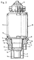
- Fig. 1 shows a longitudinal section through a housing 2 of a hand blender 1, the not to be driven device of the hand blender, for example, a blender in Fig. 1 is shown.
- the housing 2 has a substantially hollow cylindrical handle 3, which the axial end facing away from the device to be driven is closed to the outside is.
- Handle 3 closes the housing 2 with another part, the housing coupling 4 from.
- the handle 3 has a hollow cylindrical housing wall whose inner diameter in the end area 3a is enlarged, while the outer diameter the handle 3 remains the same.
- the end face 3b of the housing wall of the handle 3 and the inside 3c provided with an enlarged inside diameter of the handle 3 adjacent to the end surface 3b form the connection surface to one annular, cross-sectionally L-shaped flange surface 5 of the housing coupling 4.
- the housing coupling 4 has projections 7a, 7b on its peripheral surface are designed such that a blender or a crushing container or other device to be driven can be screwed.
- a blender or a crushing container or other device to be driven are a to the housing coupling 4 Ring groove 8 and another, radially inner, axially to the device to be driven extending hollow cylindrical housing wall 9 is provided.
- the electric motor unit 10 has a cylindrical metal housing casing 11 and a plastic end cap 12 on one of the two axial ends of the Electric motor unit 10, wherein the end cap 12 is not one in the drawing shown commutator and covers carbon brushes for electrical tapping.
- the end cap 12 essentially closes the electric motor unit to the axial one Side down, which faces away from the device to be driven, so that about a third to half of the cavity in the handle 3 is not from the electric motor unit 10 are occupied and available for a circuit board and other hand blender components stand. Neither the end cap 12 nor the housing casing 11 are on the handle 3 attached.
- the board connected to the end cap 12 is in the axial direction pushed onto the end cap and offers a over a larger axial range Contact surface for electrical connection to the motor.
- the board Through the board is also no limitation of the longitudinal tolerances of the electric motor given that to the electric motor opposite end of the board with connecting elements for power supply is connected, the board also mainly in the axial direction of the Stick mixers can be moved. Between the housing casing 11 and the An air gap is provided on the inside of the handle 3, which is an undesirable one Heat transfer between the motor and the handle 3 prevented.
- the motor housing casing 11 and the motor itself has the electric motor unit 10 on its facing the device to be driven End a motor coupling 13 in which the motor shaft with its drive teeth is stored. Via the motor coupling 13, the shaft of the device to be driven coupled to the motor drive or the electric motor unit 10.
- the engine coupling 13 is in one piece by an engine end plate 14 and an alternating cylindrical and tapered cylinder section 15 is formed.
- the plate 14 is directly attached to the housing casing 11 and has an outer diameter smaller than the casing 11.
- a cylinder section perpendicular to the plate 14 in the direction to be driven Trained device that tapers conically in the further course, then continues cylindrical, tapering again slightly, in a short The area continues cylindrically and suddenly radially expanded and continued cylindrical, so that an annular groove or locking groove 16th is formed for a snap or snap connection.
- a conical section is formed on the motor coupling, the one with a hollow cylindrical section finally to the device to be driven ends with the smallest overall radius of the cylinder section 15.
- the essentially hollow cylindrical inner wall of the housing coupling 4 has an annular locking lug 17, the shape - but not in the dimensioning - Corresponds to the locking groove 16 of the motor coupling, so that the one to be driven Device facing section of the locking lug or the locking ring 17 a vertical to the drive axis aligned wall section and in the opposite Directional section widens conically.
- the inner wall of the Housing coupling 4 has - furthermore, facing away from the device to be driven Course - two cylindrical sections, apart from an axial offset correspond to those of the motor coupling.
- the housing coupling widens then conical at a 45 ° angle to the previously axially parallel housing wall and finally runs parallel to plate 14 after another 45 ° bend.
- the plate 14 and the cylindrical Section 15 of the motor coupling has an annular gap that cross-section the shape of an isosceles triangle, formed by an annular seal 19 is inserted.
- the ring seal 19 is designed as a rubber O-ring.
- the snap or snap connection no rigid connection between the motor coupling and the housing coupling produces, so that although the ring seal 19 in a connection between both parts are slightly compressed due to the low axial and lateral However, play dampens both axial and lateral engine vibrations compensates.
- the ring seal 19 further prevents liquid from entering Housing interior and does not require tight manufacturing tolerances between the dimensions two plastic parts of the housing coupling 4, which are made of coarse polypropylene Tolerances can be produced as the motor coupling 13 made of glass fiber reinforced Polyamide can be manufactured with smaller tolerances.
- the electric motor unit is by means of a tensioning device (formed by one side of the snap or snap connection and one side of the ring seal) is clamped axially in the hand blender housing attached that axial and axially pivoting engine vibrations already through this one-sided storage ideal due to the elastic part of the tensioning device Ring seal 19 are absorbed.
- a tensioning device formed by one side of the snap or snap connection and one side of the ring seal
Landscapes
- Engineering & Computer Science (AREA)
- Mechanical Engineering (AREA)
- Food Science & Technology (AREA)
- Food-Manufacturing Devices (AREA)
- Processing And Handling Of Plastics And Other Materials For Molding In General (AREA)
Applications Claiming Priority (2)
| Application Number | Priority Date | Filing Date | Title |
|---|---|---|---|
| DE19718482A DE19718482A1 (de) | 1997-04-30 | 1997-04-30 | Stabmixer und Verfahren zur Montage eines Stabmixers |
| DE19718482 | 1997-04-30 |
Publications (2)
| Publication Number | Publication Date |
|---|---|
| EP0875191A1 true EP0875191A1 (fr) | 1998-11-04 |
| EP0875191B1 EP0875191B1 (fr) | 1999-08-25 |
Family
ID=7828356
Family Applications (1)
| Application Number | Title | Priority Date | Filing Date |
|---|---|---|---|
| EP98105379A Expired - Lifetime EP0875191B1 (fr) | 1997-04-30 | 1998-03-25 | Pied mélangeur et méthode pour monter un pied mélangeur |
Country Status (4)
| Country | Link |
|---|---|
| EP (1) | EP0875191B1 (fr) |
| AT (1) | ATE183625T1 (fr) |
| DE (2) | DE19718482A1 (fr) |
| ES (1) | ES2138869T3 (fr) |
Cited By (2)
| Publication number | Priority date | Publication date | Assignee | Title |
|---|---|---|---|---|
| WO2003020090A3 (fr) * | 2001-08-29 | 2003-10-09 | Bsh Bosch Siemens Hausgeraete | Appareil de cuisine |
| EP4674490A1 (fr) | 2024-07-04 | 2026-01-07 | T1TAN GmbH | Gant de gardien de but pourvu d'une extension |
Families Citing this family (1)
| Publication number | Priority date | Publication date | Assignee | Title |
|---|---|---|---|---|
| DE102007054276A1 (de) | 2007-11-09 | 2009-05-14 | Matthias Heinke | Vorrichtung, Luftinjektor, in Zusammenwirkung mit einem Stabmixgerät |
Citations (3)
| Publication number | Priority date | Publication date | Assignee | Title |
|---|---|---|---|---|
| DE1091719B (de) * | 1959-05-22 | 1960-10-27 | Metabowerk Closs Rauch & Schni | Elektrisches Handmixgeraet |
| CH604654A5 (en) * | 1976-10-29 | 1978-09-15 | Kenwood Mfg Co Ltd | Easily assembled electric food mixer |
| DE3709573A1 (de) | 1987-03-24 | 1988-10-06 | Braun Ag | Handmixgeraet, insbesondere stabmixer |
Family Cites Families (2)
| Publication number | Priority date | Publication date | Assignee | Title |
|---|---|---|---|---|
| DE605203C (de) * | 1934-11-06 | Neue Elektro Bohner G M B H | Aufhaengung von elektrischen Flanschmotoren mittels Gummibuechsen | |
| DE1162519B (de) * | 1960-08-13 | 1964-02-06 | Esge Exp A G | Elektromotorisch angetriebenes Handmixgeraet |
-
1997
- 1997-04-30 DE DE19718482A patent/DE19718482A1/de not_active Withdrawn
-
1998
- 1998-03-25 EP EP98105379A patent/EP0875191B1/fr not_active Expired - Lifetime
- 1998-03-25 AT AT98105379T patent/ATE183625T1/de not_active IP Right Cessation
- 1998-03-25 ES ES98105379T patent/ES2138869T3/es not_active Expired - Lifetime
- 1998-03-25 DE DE59800023T patent/DE59800023D1/de not_active Expired - Lifetime
Patent Citations (3)
| Publication number | Priority date | Publication date | Assignee | Title |
|---|---|---|---|---|
| DE1091719B (de) * | 1959-05-22 | 1960-10-27 | Metabowerk Closs Rauch & Schni | Elektrisches Handmixgeraet |
| CH604654A5 (en) * | 1976-10-29 | 1978-09-15 | Kenwood Mfg Co Ltd | Easily assembled electric food mixer |
| DE3709573A1 (de) | 1987-03-24 | 1988-10-06 | Braun Ag | Handmixgeraet, insbesondere stabmixer |
Cited By (4)
| Publication number | Priority date | Publication date | Assignee | Title |
|---|---|---|---|---|
| WO2003020090A3 (fr) * | 2001-08-29 | 2003-10-09 | Bsh Bosch Siemens Hausgeraete | Appareil de cuisine |
| RU2287975C2 (ru) * | 2001-08-29 | 2006-11-27 | Бсх Бош Унд Сименс Хаусгерете Гмбх | Кухонный прибор |
| US7228794B2 (en) | 2001-08-29 | 2007-06-12 | Bsh Bosch Und Siemens Hausgeraete Gmbh | Kitchen appliance |
| EP4674490A1 (fr) | 2024-07-04 | 2026-01-07 | T1TAN GmbH | Gant de gardien de but pourvu d'une extension |
Also Published As
| Publication number | Publication date |
|---|---|
| EP0875191B1 (fr) | 1999-08-25 |
| DE19718482A1 (de) | 1998-11-05 |
| DE59800023D1 (de) | 1999-09-30 |
| ATE183625T1 (de) | 1999-09-15 |
| ES2138869T3 (es) | 2000-01-16 |
Similar Documents
| Publication | Publication Date | Title |
|---|---|---|
| EP0920723A1 (fr) | Unite d'entrainement electrique | |
| EP1441933A1 (fr) | Systeme d'essuie-glace pour vitre d'automobile | |
| DE10245971A1 (de) | Elektromotor mit schraubenloser Steckmontage | |
| DE10018156A1 (de) | Elektromotor | |
| DE102009043322A1 (de) | Elektromotorischer Hilfsantrieb | |
| DE102004005067A1 (de) | Scheibenwischvorrichtung, insbesondere für ein Kraftfahrzeug | |
| EP2532061B1 (fr) | Appareil électrique pourvu d'un passage pour un câble à travers une paroi de boîtier | |
| EP2622719B1 (fr) | Structure de liaison pour lier mécaniquement un premier boîtier et un deuxième boîtier | |
| DE2750477A1 (de) | Antriebsvorrichtung, insbesondere fuer scheibenwischer | |
| DE4301504C2 (de) | Elektrischer Steckverbinder | |
| EP0875191B1 (fr) | Pied mélangeur et méthode pour monter un pied mélangeur | |
| EP0105392A2 (fr) | Boîte porte-balai pour un électromoteur à commutateur | |
| EP1078440B1 (fr) | Organe de commande a moteur electrique, notamment organe de commande de leve-vitre pour un vehicule automobile | |
| EP0446466A1 (fr) | Dispositif de couplage de traversée de paroi pour une connexion électrique | |
| EP0599063A1 (fr) | Unité d'entraînement avec moteur électrique d'entraînement | |
| DE102005026148B4 (de) | Steckverbinderkupplung | |
| WO2007124838A1 (fr) | Système de direction pour véhicules et procédé de montage d'un ensemble support | |
| EP1046213A1 (fr) | Dispositif d'entrainement electromoteur | |
| EP1176674A2 (fr) | Connecteur électrique | |
| DE2522600C2 (de) | Anordnung für einen Lenkstockschalter für Kraftfahrzeuge | |
| EP1377765A1 (fr) | Engrenage, notamment engrenage a vis sans fin | |
| EP2114737A1 (fr) | Dispositif d'étanchéité pour un arbre menant d'une commande d'essuie-glace, système de montage des dispositifs d'étanchéité correspondants et commande d'essuie-glace correspondante | |
| DE102005000084A1 (de) | Verstellvorrichtung zur Drehrichtungsumkehr | |
| DE3514684C2 (fr) | ||
| WO2007124840A1 (fr) | Système de direction pour véhicules |
Legal Events
| Date | Code | Title | Description |
|---|---|---|---|
| PUAI | Public reference made under article 153(3) epc to a published international application that has entered the european phase |
Free format text: ORIGINAL CODE: 0009012 |
|
| AK | Designated contracting states |
Kind code of ref document: A1 Designated state(s): AT BE CH DE ES FR GB LI NL |
|
| AX | Request for extension of the european patent |
Free format text: AL;LT;LV;MK;RO;SI |
|
| 17P | Request for examination filed |
Effective date: 19981125 |
|
| GRAG | Despatch of communication of intention to grant |
Free format text: ORIGINAL CODE: EPIDOS AGRA |
|
| GRAH | Despatch of communication of intention to grant a patent |
Free format text: ORIGINAL CODE: EPIDOS IGRA |
|
| 17Q | First examination report despatched |
Effective date: 19990114 |
|
| GRAH | Despatch of communication of intention to grant a patent |
Free format text: ORIGINAL CODE: EPIDOS IGRA |
|
| GRAA | (expected) grant |
Free format text: ORIGINAL CODE: 0009210 |
|
| AKX | Designation fees paid |
Free format text: AT BE CH DE ES FR GB LI NL |
|
| RBV | Designated contracting states (corrected) |
Designated state(s): AT BE CH DE ES FR GB LI NL |
|
| AK | Designated contracting states |
Kind code of ref document: B1 Designated state(s): AT BE CH DE ES FR GB LI NL |
|
| REF | Corresponds to: |
Ref document number: 183625 Country of ref document: AT Date of ref document: 19990915 Kind code of ref document: T |
|
| REG | Reference to a national code |
Ref country code: CH Ref legal event code: EP |
|
| DAX | Request for extension of the european patent (deleted) | ||
| REF | Corresponds to: |
Ref document number: 59800023 Country of ref document: DE Date of ref document: 19990930 |
|
| GBT | Gb: translation of ep patent filed (gb section 77(6)(a)/1977) |
Effective date: 19991119 |
|
| RAP2 | Party data changed (patent owner data changed or rights of a patent transferred) |
Owner name: BRAUN GMBH |
|
| ET | Fr: translation filed | ||
| REG | Reference to a national code |
Ref country code: ES Ref legal event code: FG2A Ref document number: 2138869 Country of ref document: ES Kind code of ref document: T3 |
|
| NLT2 | Nl: modifications (of names), taken from the european patent patent bulletin |
Owner name: BRAUN GMBH |
|
| PGFP | Annual fee paid to national office [announced via postgrant information from national office to epo] |
Ref country code: AT Payment date: 20000320 Year of fee payment: 3 |
|
| PGFP | Annual fee paid to national office [announced via postgrant information from national office to epo] |
Ref country code: BE Payment date: 20000321 Year of fee payment: 3 |
|
| REG | Reference to a national code |
Ref country code: FR Ref legal event code: CD Ref country code: FR Ref legal event code: CA |
|
| REG | Reference to a national code |
Ref country code: CH Ref legal event code: NV Representative=s name: LUCHS & PARTNER PATENTANWAELTE |
|
| PLBE | No opposition filed within time limit |
Free format text: ORIGINAL CODE: 0009261 |
|
| STAA | Information on the status of an ep patent application or granted ep patent |
Free format text: STATUS: NO OPPOSITION FILED WITHIN TIME LIMIT |
|
| 26N | No opposition filed | ||
| REG | Reference to a national code |
Ref country code: CH Ref legal event code: PFA Free format text: BRAUN AKTIENGESELLSCHAFT TRANSFER- BRAUN AKTIENGESELLSCHAFT;BRAUN GMBH |
|
| PG25 | Lapsed in a contracting state [announced via postgrant information from national office to epo] |
Ref country code: AT Free format text: LAPSE BECAUSE OF NON-PAYMENT OF DUE FEES Effective date: 20010325 |
|
| PG25 | Lapsed in a contracting state [announced via postgrant information from national office to epo] |
Ref country code: BE Free format text: LAPSE BECAUSE OF NON-PAYMENT OF DUE FEES Effective date: 20010331 |
|
| BERE | Be: lapsed |
Owner name: BRAUN A.G. Effective date: 20010331 |
|
| REG | Reference to a national code |
Ref country code: GB Ref legal event code: IF02 |
|
| PGFP | Annual fee paid to national office [announced via postgrant information from national office to epo] |
Ref country code: CH Payment date: 20030403 Year of fee payment: 6 |
|
| PG25 | Lapsed in a contracting state [announced via postgrant information from national office to epo] |
Ref country code: LI Free format text: LAPSE BECAUSE OF NON-PAYMENT OF DUE FEES Effective date: 20040331 Ref country code: CH Free format text: LAPSE BECAUSE OF NON-PAYMENT OF DUE FEES Effective date: 20040331 |
|
| REG | Reference to a national code |
Ref country code: CH Ref legal event code: PL |
|
| PGFP | Annual fee paid to national office [announced via postgrant information from national office to epo] |
Ref country code: GB Payment date: 20050308 Year of fee payment: 8 |
|
| PGFP | Annual fee paid to national office [announced via postgrant information from national office to epo] |
Ref country code: NL Payment date: 20050322 Year of fee payment: 8 |
|
| PG25 | Lapsed in a contracting state [announced via postgrant information from national office to epo] |
Ref country code: GB Free format text: LAPSE BECAUSE OF NON-PAYMENT OF DUE FEES Effective date: 20060325 |
|
| PG25 | Lapsed in a contracting state [announced via postgrant information from national office to epo] |
Ref country code: NL Free format text: LAPSE BECAUSE OF NON-PAYMENT OF DUE FEES Effective date: 20061001 |
|
| GBPC | Gb: european patent ceased through non-payment of renewal fee |
Effective date: 20060325 |
|
| NLV4 | Nl: lapsed or anulled due to non-payment of the annual fee |
Effective date: 20061001 |
|
| REG | Reference to a national code |
Ref country code: FR Ref legal event code: PLFP Year of fee payment: 19 |
|
| REG | Reference to a national code |
Ref country code: FR Ref legal event code: PLFP Year of fee payment: 20 |
|
| PGFP | Annual fee paid to national office [announced via postgrant information from national office to epo] |
Ref country code: FR Payment date: 20170222 Year of fee payment: 20 |
|
| PGFP | Annual fee paid to national office [announced via postgrant information from national office to epo] |
Ref country code: ES Payment date: 20170308 Year of fee payment: 20 |
|
| PGFP | Annual fee paid to national office [announced via postgrant information from national office to epo] |
Ref country code: DE Payment date: 20170331 Year of fee payment: 20 |
|
| REG | Reference to a national code |
Ref country code: DE Ref legal event code: R071 Ref document number: 59800023 Country of ref document: DE |
|
| REG | Reference to a national code |
Ref country code: ES Ref legal event code: FD2A Effective date: 20201201 |
|
| PG25 | Lapsed in a contracting state [announced via postgrant information from national office to epo] |
Ref country code: ES Free format text: LAPSE BECAUSE OF EXPIRATION OF PROTECTION Effective date: 20180326 |