EP0875205A1 - Ecarteur chirurgical - Google Patents
Ecarteur chirurgical Download PDFInfo
- Publication number
- EP0875205A1 EP0875205A1 EP98107949A EP98107949A EP0875205A1 EP 0875205 A1 EP0875205 A1 EP 0875205A1 EP 98107949 A EP98107949 A EP 98107949A EP 98107949 A EP98107949 A EP 98107949A EP 0875205 A1 EP0875205 A1 EP 0875205A1
- Authority
- EP
- European Patent Office
- Prior art keywords
- frame
- surgical retractor
- hook member
- retractor assembly
- assembly according
- Prior art date
- Legal status (The legal status is an assumption and is not a legal conclusion. Google has not performed a legal analysis and makes no representation as to the accuracy of the status listed.)
- Granted
Links
- 230000007246 mechanism Effects 0.000 claims abstract description 12
- 238000000034 method Methods 0.000 description 14
- 210000001519 tissue Anatomy 0.000 description 12
- 238000001356 surgical procedure Methods 0.000 description 9
- 210000001349 mammary artery Anatomy 0.000 description 8
- 230000000712 assembly Effects 0.000 description 6
- 238000000429 assembly Methods 0.000 description 6
- 239000000463 material Substances 0.000 description 6
- 210000000988 bone and bone Anatomy 0.000 description 5
- 210000000038 chest Anatomy 0.000 description 3
- 210000001367 artery Anatomy 0.000 description 2
- 230000003028 elevating effect Effects 0.000 description 2
- 238000012986 modification Methods 0.000 description 2
- 230000004048 modification Effects 0.000 description 2
- 230000002093 peripheral effect Effects 0.000 description 2
- 239000003381 stabilizer Substances 0.000 description 2
- 229910001220 stainless steel Inorganic materials 0.000 description 2
- 239000010935 stainless steel Substances 0.000 description 2
- 210000000115 thoracic cavity Anatomy 0.000 description 2
- 206010002329 Aneurysm Diseases 0.000 description 1
- 210000004204 blood vessel Anatomy 0.000 description 1
- 238000007675 cardiac surgery Methods 0.000 description 1
- 230000002612 cardiopulmonary effect Effects 0.000 description 1
- 208000029078 coronary artery disease Diseases 0.000 description 1
- 238000003745 diagnosis Methods 0.000 description 1
- 238000006073 displacement reaction Methods 0.000 description 1
- 238000002224 dissection Methods 0.000 description 1
- 238000002324 minimally invasive surgery Methods 0.000 description 1
- 210000000056 organ Anatomy 0.000 description 1
- 229920000515 polycarbonate Polymers 0.000 description 1
- 239000004417 polycarbonate Substances 0.000 description 1
- 238000011084 recovery Methods 0.000 description 1
- 239000007787 solid Substances 0.000 description 1
- 210000001562 sternum Anatomy 0.000 description 1
- 210000000779 thoracic wall Anatomy 0.000 description 1
- 230000000472 traumatic effect Effects 0.000 description 1
- 230000002792 vascular Effects 0.000 description 1
- 238000007631 vascular surgery Methods 0.000 description 1
Images



Classifications
-
- A—HUMAN NECESSITIES
- A61—MEDICAL OR VETERINARY SCIENCE; HYGIENE
- A61B—DIAGNOSIS; SURGERY; IDENTIFICATION
- A61B17/00—Surgical instruments, devices or methods
- A61B17/02—Surgical instruments, devices or methods for holding wounds open, e.g. retractors; Tractors
- A61B17/0206—Surgical instruments, devices or methods for holding wounds open, e.g. retractors; Tractors with antagonistic arms as supports for retractor elements
-
- A—HUMAN NECESSITIES
- A61—MEDICAL OR VETERINARY SCIENCE; HYGIENE
- A61B—DIAGNOSIS; SURGERY; IDENTIFICATION
- A61B17/00—Surgical instruments, devices or methods
- A61B17/02—Surgical instruments, devices or methods for holding wounds open, e.g. retractors; Tractors
- A61B17/0293—Surgical instruments, devices or methods for holding wounds open, e.g. retractors; Tractors with ring member to support retractor elements
Definitions
- the disclosure relates to a surgical apparatus and method and more particularly to a minimally invasive surgical apparatus and method for retracting tissue.
- IMA internal mammary artery
- the apparatus and method disclosed herein provides improved surgical access through a minimally invasive window approach. This is achieved by providing a surgical retractor assembly comprising a frame lying in first plane, at least one elevation control supporting the frame and configured to selectively lift at least a portion of the frame out of the first plane, and at least one hook member supported on the frame and configured to retract tissue.
- a second hook member is preferably removably mounted to the frame and configured to retract tissue in a direction away from the at least one hook member.
- the elevation control assembly may comprise a pair of elongated shafts removably mounted to the frame with each of the control assemblies including a locking mechanism to retain the frame in the selected position.
- a surgical retractor assembly comprising a frame, a first hook member supported on the frame, a second hook member supported on the frame and movable with respect to the frame, and a frame support supporting the frame and adapted to retain a first portion of the frame in a selected raised position with respect to a second portion of the frame.
- a method for accessing the internal mammary artery in a minimally invasive procedure comprising placing a first hook member supported on a frame between the ribs, placing a second hook member supported on the frame between the ribs, moving the second hook member in a direction away from the first hook member to retract the ribs, elevating a first portion of the frame away from the body to a selected raised position, and retaining the first portion of the frame in the selected raised position.
- the method may further comprise the step of inserting a dissector through an opening in the frame to dissect the internal mammary artery.
- the step of elevating the first portion of the frame may comprise the step of manually sliding the first portion of the frame along first and second spaced apart shafts.
- the apparatus can be used to enable minimally invasive dissection of the internal mammary artery (IMA) by retracting the ribs to enable access to the IMA.
- IMA internal mammary artery
- the present disclosure should not be limited to an apparatus for use in conjunction with such heart surgery, but may find application in surgery wherein access to the surgical site is achieved through a small incision and retraction of the surrounding tissues and/or bone if desired.
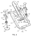
- FIGS.. 1-3 a first embodiment of the surgical retractor of the present disclosure is illustrated in FIGS.. 1-3, and is designated generally by reference numeral 100.
- Surgical retractor 100 has frame member 110 which is preferably formed of a material which is readily sterilizable after use, for example, stainless steel. Alternatively, some or all of the components may be made of disposable materials so that the apparatus could be discarded after use.
- Frame 110 has various cut-out portions and contours which may be formed by way of stamping frame 110 out of a solid sheet of material.
- a fixed hook portion 112 is provided at the lower flattened end portion 114 of frame member 110.
- Hook portion 112 is preferably provided with slotted openings 112a to facilitate gripping of bone and/or tissue, thereby preventing lateral movement of hook member 126.
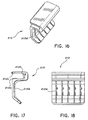
- slotted openings 1 12a may either be replaced by or supplemented with rib portions (similar to ribs 212d shown in FIGS. 16-18 and described further herein) formed on the tissue contacting areas of hook portion 112.
- Cut-out portions 116 are formed at the upper end 118 of frame member 110 to receive a pair of elevation control assemblies 120 therein.
- Circular cut-out 122 is provided in central portion 124 of frame 110 to attach an adjustable hook member 126 by way of an adjustment knob 128 passing through cut-out 130 formed at the bottom of adjustable hook member 126.
- Adjustable hook member 126 is further provided with hook portion 132 which curves inwardly through the central opening formed by frame 110.
- Hook portion 132 is preferably provided with slotted openings 132a to facilitate gripping of bone and/or tissue, thereby preventing lateral movement of hook member 126.
- slotted openings 132a may either be replaced by or supplemented with rib portions (similar to ribs 212d shown in FIGS. 16-18) formed on the tissue contacting areas of hook portion 132.
- a rack portion 134 is formed longitudinally along the main surface of adjustable hook member 126.
- a large central opening is provided and is defined by inner edge 113. This opening allows the surgeon to insert various surgical instruments through frame member 110 to perform surgical procedures. For example, in the case of a minimally invasive heart bypass procedure, dissectors can be inserted to dissect the IMA for subsequent attachment to another artery.
- elevation control assembly 120 includes an elongated shaft 136 pivotably mounted to a base portion 138 and having a dome-shaped knob 140 to facilitate gripping, attached to the top thereof.
- a locking mechanism 142 is disposed on shaft 136 and includes a collet member 144, a compressible ball-shaped member 146 and a knob-nut 148. Each of these elements includes a central opening of sufficient diameter to permit them to slide along shaft 136 when spaced apart from each other.
- Knob-nut 148 as shown in FIG.
- portion 148 defines a stepped throughbore having adjacent cylindrical step portions 148a and 148b and a frusto-conical portion 148c, each of which are axially aligned along the central longitudinal axis 148L.
- Portion 148 includes threads formed thereon.
- collet member 144 includes a tapered throughbore formed by adjoining fiusto-conical sections 144a and 144b which form neck portion 144c at their juncture. Sections 144a and 144b are axially aligned along the central longitudinal axis 144L of collet 144. External threads are formed on the outer surface 144d so as to mesh with the threads formed at step portion 148b of knob-nut 148.
- Compressible ball 146 of elevation control assembly 120 includes flexible portions 146a, as shown in FIG. 5, which flex when ball 146 is compressed between frusto-conical surface 144b and frusto-conical surface 148c ofthe collet 144 and knob-nut 148, respectively. In this manner, when knob-nut 148 is threaded onto collet 144, ball 146 is compressed so that finger portions 146a are biased against shaft 136 so as to lock the locking mechanism 142 and prevent axial movement of the assembly along shaft 136. This locking action prevents axial movement of frame member 110 along shaft 136 as well thereby locking frame member in a fixed position.
- adjustable hook member 126 includes a cut-out 130 which is configured and dimensioned to receive a circular base 128a of adjustment knob 128.
- Circular base 128a together with a second circular base 128b form a gap region which is slightly greater than the thickness of the plate material which forms adjustable hook member 126.
- adjustment knob 128 may be slid along adjustable hook member 126 until post members 128c become seated in the first valley 126a which are formed by the gaps between teeth 126b disposed along one side of a longitudinal opening extending along adjustable hook member 126.
- adjustable hook member 126 may be adjusted toward or away from fixed portion 112 by rotating adjustment knob 128 in the desired direction so that post members 128c bias against the sidewalls of teeth 126b and urge adjustable hook member 126 in the desired direction due to the fixed nature of adjustment knob 128 with respect to frame member 110.
- the frame member 110 with the adjustable hook member 126 disposed thereon is inserted between the structures desired to be retracted, for example, in the case of heart surgery the retractor hooks are inserted between the fourth and fifth ribs so that hook portion 132 biases against a first of these ribs and hook portion 112 biases against a second of these ribs in opposite directions.
- the retractor frame 112 is substantially parallel to the ribs.
- Adjustment knob 128 is turned clockwise in the embodiment shown in FIGS. 1-11 to retract hook portion 132 away from hook portion 112 until the desired opening is achieved between the adjacent ribs.
- the outwardly extending end 118 of frame 110 is then elevated by first loosening locking mechanism 142 on each of the elevation control assemblies 120 and raising end 118 of the frame member so as to elevate one side of the retractor 100.
- locking mechanism 142 is locked as described above to fix the axial location of frame end 118 relative to the shaft 136 of each of elevation control assemblies 120. After the surgical procedure is complete, surgical retractor 100 can be completely disassembled and sterilized for reuse.
- surgical retractor 200 is a disposable assembly which may be discarded after use.
- the various components of surgical retractor 200 may be made of light weight polycarbonate materials.
- the various components of surgical retractor 200 may also be made of materials such as stainless steel which may be sterilized and reused if desired.
- Surgical retractor 200 includes an oval shaped ring member 211 which defines an inner window area as defined by inner edge 211a.
- This window area like the opening in frame member 110 of the previously described embodiment, allows the surgeon to insert various surgical instruments through ring member 211 to perform surgical procedures.
- Ring 211 further includes a peripheral lip 211b which extends outwardly along the upper outer periphery of ring member 211.
- Inner edge 211a is preferably beveled inwardly so as to define a smooth surface along the perimeter of the operating window.
- a removable hook member 212 is snap fitted onto ring member 211 along a first straight portion disposed on one side of ring member 211 and a base portion 223 is similarly snap fitted to a second straight portion disposed on the opposite side of ring member 211.
- removable hook 212 and base 223 are molded parts, each of which will be described in further detail herein.
- An adjustable hook 226 is attached to base 223 by adjustment knob 228 which snap fits into base 223.
- adjustment knob 228 may be threaded into base 223.
- adjustable hook 226 is similar to that described above in connection with the embodiment of FIG. 1. Accordingly, that operation will not be described in further detail herein. However, it should be noted that adjustable hook 226 which has slotted openings 226a formed thereon to facilitate gripping of tissue and/or bone could be provided with projecting rib portions (similar to rib portions 212d described further herein) either in place of or in conjunction with slotted openings 226a.
- a pair of vertical stabilizers 220 are also provided for surgical retractor 200 and are attached to base 223 in openings 216 formed on opposite ends of the base member.
- vertical stabilizer members 220 are designed to hold base 223 and therefore, one side of ring member 211 at a fixed elevation relative to bases 238.
- collet 244, ball 246 and knob-nut 248 work in similar fashion as locking mechanism 142 in order to lock frame member 223 in position relative to the patient's chest wall.
- ring member 211 is adapted to have various other instruments connected or attached thereto as desired.
- base member 223 is shown having slot 223a formed therein with minor slot 223b formed at the top of slot 223a.
- Slot 223b facilitates receiving the lip 211b of ring member 211 and lip portion 223c facilitates snap fitting locking type arrangement of base 223 onto ring member 211.
- ring member 211 could have a peripheral groove formed thereon whereas base 223 and removable hook 212 could each have a projecting lip formed thereon which would facilitate attachment of these elements to ring member 211.
- removable hook 212 includes an elongated slot 212a formed therein and a minor slot 212b formed therein to facilitate attachment of removable hook member 212 to ring member 211 in a similar manner of attachment of base 223 thereto.
- removable hook member 212 includes a raised surface portion 212c which facilitates the snap fitting of removable hook to the ring 11.
- Removable hook member 212 is provided with protruding rib portions 212d which extend outwardly from the body contacting surface of removable hook member 212. Rib portions 212d prevent lateral movement of the hook member relative to the contacted body portion, e.g., the rib section.
- rib portions 212d could be replaced with or supplemented by slotted openings to allow body tissue and/or bone to engage the openings.
Landscapes
- Health & Medical Sciences (AREA)
- Life Sciences & Earth Sciences (AREA)
- Surgery (AREA)
- Heart & Thoracic Surgery (AREA)
- Engineering & Computer Science (AREA)
- Biomedical Technology (AREA)
- Nuclear Medicine, Radiotherapy & Molecular Imaging (AREA)
- Medical Informatics (AREA)
- Molecular Biology (AREA)
- Animal Behavior & Ethology (AREA)
- General Health & Medical Sciences (AREA)
- Public Health (AREA)
- Veterinary Medicine (AREA)
- Surgical Instruments (AREA)
Applications Claiming Priority (4)
| Application Number | Priority Date | Filing Date | Title |
|---|---|---|---|
| US4548797P | 1997-05-02 | 1997-05-02 | |
| US45487P | 1997-05-02 | ||
| US08/994,686 US5967974A (en) | 1997-05-02 | 1997-12-19 | Surgical retractor |
| US994686 | 1997-12-19 |
Publications (2)
| Publication Number | Publication Date |
|---|---|
| EP0875205A1 true EP0875205A1 (fr) | 1998-11-04 |
| EP0875205B1 EP0875205B1 (fr) | 2003-09-03 |
Family
ID=26722834
Family Applications (1)
| Application Number | Title | Priority Date | Filing Date |
|---|---|---|---|
| EP98107949A Expired - Lifetime EP0875205B1 (fr) | 1997-05-02 | 1998-04-30 | Ecarteur chirurgical |
Country Status (4)
| Country | Link |
|---|---|
| US (1) | US5967974A (fr) |
| EP (1) | EP0875205B1 (fr) |
| CA (1) | CA2236341C (fr) |
| DE (1) | DE69817664T2 (fr) |
Cited By (1)
| Publication number | Priority date | Publication date | Assignee | Title |
|---|---|---|---|---|
| EP0980674A3 (fr) * | 1998-07-13 | 2000-03-01 | United States Surgical Corporation | Ecarteur chirurgical |
Families Citing this family (17)
| Publication number | Priority date | Publication date | Assignee | Title |
|---|---|---|---|---|
| US6200263B1 (en) | 1998-01-23 | 2001-03-13 | United States Surgical Corporation | Surgical instrument holder |
| US6199556B1 (en) * | 1998-05-01 | 2001-03-13 | Cardiothoracic Systems, Inc. | Xyphoid access for cardiac surgical procedures |
| US6258023B1 (en) | 1999-07-08 | 2001-07-10 | Chase Medical, Inc. | Device and method for isolating a surface of a beating heart during surgery |
| US6464634B1 (en) * | 2000-09-27 | 2002-10-15 | Depuy Acromed, Inc. | Surgical retractor system |
| US7137949B2 (en) * | 2001-07-13 | 2006-11-21 | United States Surgical Corporation | Surgical instrument |
| US7186215B2 (en) * | 2002-06-24 | 2007-03-06 | James Yi | Lifting tool for surgical retractors |
| US7270632B2 (en) * | 2004-09-03 | 2007-09-18 | Santilli Albert N | Surgical retractor having lifting capability |
| US7625339B2 (en) * | 2004-12-15 | 2009-12-01 | Depuy Spine, Inc. | Retractor blade extender tower |
| US7993244B2 (en) * | 2008-06-06 | 2011-08-09 | Weller Scott M | Cushioning device and spring floor system incorporating same |
| US8974381B1 (en) | 2011-04-26 | 2015-03-10 | Nuvasive, Inc. | Cervical retractor |
| US8900137B1 (en) | 2011-04-26 | 2014-12-02 | Nuvasive, Inc. | Cervical retractor |
| WO2013028571A1 (fr) | 2011-08-19 | 2013-02-28 | Lanx, Inc. | Système d'écarteur chirurgical et procédés d'utilisation |
| US9113853B1 (en) | 2011-08-31 | 2015-08-25 | Nuvasive, Inc. | Systems and methods for performing spine surgery |
| CN103987327A (zh) * | 2011-10-05 | 2014-08-13 | 马克·A·多德森 | 模块化牵开器及相关方法 |
| US8852090B2 (en) * | 2012-03-13 | 2014-10-07 | Globus Medical, Inc. | System and method for retracting body tissue |
| US9084441B1 (en) * | 2012-09-28 | 2015-07-21 | Ephriam Azer | Collapsible collar stay |
| DE102013104300A1 (de) * | 2013-04-26 | 2014-11-13 | Aesculap Ag | Teleskopierbare Retraktorhalterung |
Citations (5)
| Publication number | Priority date | Publication date | Assignee | Title |
|---|---|---|---|---|
| US2594086A (en) * | 1950-04-29 | 1952-04-22 | David P Smith | Table supported abdominal retractor |
| GB2102681A (en) * | 1981-07-27 | 1983-02-09 | Codman & Shurtleff | Surgical retractor holder |
| US4457300A (en) * | 1982-06-07 | 1984-07-03 | Ohio Medical Instrument Co., Inc. | Surgical retractor |
| EP0336526A1 (fr) * | 1988-02-25 | 1989-10-11 | Steven J. Phillips | Appareil rétracteur pour utiliser dans la récupération d'artères mammaires pendant une opération de pontage cardiaque |
| EP0808606A1 (fr) | 1996-04-26 | 1997-11-26 | United States Surgical Corporation | Ecarteur chirurgical |
Family Cites Families (31)
| Publication number | Priority date | Publication date | Assignee | Title |
|---|---|---|---|---|
| US34150A (en) * | 1862-01-14 | Improved water-wheel | ||
| US1400616A (en) * | 1921-01-10 | 1921-12-20 | Harvey B Mccrory | Abdominal retractor |
| US1963173A (en) * | 1933-01-03 | 1934-06-19 | Horace Lauzon | Retractor |
| US2623517A (en) * | 1950-06-29 | 1952-12-30 | Barlow Israel Owen | Surgical abdominal retractor |
| US2670732A (en) * | 1952-08-11 | 1954-03-02 | Ole A Nelson | Surgical retractor |
| US2751903A (en) * | 1954-04-22 | 1956-06-26 | Harry S Ivory | Adjustable retractor for surgical use |
| US2812759A (en) * | 1956-06-21 | 1957-11-12 | Harry R Taylor | Abdominal retractor |
| US3040739A (en) * | 1959-07-17 | 1962-06-26 | Herman R Grieshaber | Surgical retractor |
| US3965890A (en) * | 1974-10-18 | 1976-06-29 | William Kohlmann Gauthier | Surgical retractor |
| US3998217A (en) * | 1975-01-13 | 1976-12-21 | William E. Trumbull | Surgical retractor device |
| US4254763A (en) * | 1979-06-07 | 1981-03-10 | Codman & Shurtleff, Inc. | Surgical retractor assembly |
| US4380999A (en) * | 1980-07-15 | 1983-04-26 | Healy Keelin E | Stepped surgical retractor |
| US4747395A (en) * | 1983-08-24 | 1988-05-31 | Brief L Paul | Surgical retractor for bone surgery |
| US4627421A (en) * | 1984-08-03 | 1986-12-09 | Symbas Panagiotis N | Sternal retractor |
| USRE34150E (en) | 1985-11-12 | 1992-12-29 | Kapp Surgical Instrument, Inc. | Cardiovascular and thoracic retractor |
| US4726356A (en) * | 1985-11-12 | 1988-02-23 | Kapp Surgical Instrument, Inc. | Cardiovascular and thoracic retractor |
| FR2599238B1 (fr) * | 1986-05-28 | 1988-08-19 | Delacroix Chevalier Sa | Ecarteur sternal. |
| US4813401A (en) * | 1986-11-26 | 1989-03-21 | Grieshaber Manufacturing Company | Retractor |
| US4702230A (en) * | 1986-12-08 | 1987-10-27 | Pilling Co. | Adapter for surgical retractor |
| JP2629693B2 (ja) * | 1987-02-26 | 1997-07-09 | 松下電器産業株式会社 | エキシマレーザ用ミラー |
| US5000163A (en) * | 1987-06-25 | 1991-03-19 | Surgical Dynamics, Inc. | Retraction device |
| US4852552A (en) * | 1987-09-03 | 1989-08-01 | Pilling Co. | Sternal retractor |
| US4884559A (en) * | 1987-12-04 | 1989-12-05 | Collins Jason H | Surgical speculum |
| SE8802904D0 (sv) * | 1988-08-16 | 1988-08-16 | Mogens Bugge | Dr mogens bugge's mammaria hake |
| US4971038A (en) * | 1989-04-26 | 1990-11-20 | Farley Daniel K | Table mounted surgical retractor |
| GB2233561B (en) * | 1989-07-07 | 1993-03-24 | Engineering In Medicine Limite | Clamp assemblies |
| US5520610A (en) * | 1991-05-31 | 1996-05-28 | Giglio; Steven R. | Self retaining retractor |
| US5231974A (en) * | 1991-05-31 | 1993-08-03 | Giglio Steven R | Self retaining retractor |
| US5375481A (en) * | 1993-11-12 | 1994-12-27 | Codman & Shurtleff, Inc. | Multi-position ratchet mechanism |
| US5503617A (en) * | 1994-07-19 | 1996-04-02 | Jako; Geza J. | Retractor and method for direct access endoscopic surgery |
| US5882299A (en) * | 1997-01-31 | 1999-03-16 | Minnesota Scientific, Inc. | Device and procedure for minimally invasive coronary anastomosis |
-
1997
- 1997-12-19 US US08/994,686 patent/US5967974A/en not_active Expired - Lifetime
-
1998
- 1998-04-30 EP EP98107949A patent/EP0875205B1/fr not_active Expired - Lifetime
- 1998-04-30 DE DE69817664T patent/DE69817664T2/de not_active Expired - Lifetime
- 1998-04-30 CA CA002236341A patent/CA2236341C/fr not_active Expired - Fee Related
Patent Citations (5)
| Publication number | Priority date | Publication date | Assignee | Title |
|---|---|---|---|---|
| US2594086A (en) * | 1950-04-29 | 1952-04-22 | David P Smith | Table supported abdominal retractor |
| GB2102681A (en) * | 1981-07-27 | 1983-02-09 | Codman & Shurtleff | Surgical retractor holder |
| US4457300A (en) * | 1982-06-07 | 1984-07-03 | Ohio Medical Instrument Co., Inc. | Surgical retractor |
| EP0336526A1 (fr) * | 1988-02-25 | 1989-10-11 | Steven J. Phillips | Appareil rétracteur pour utiliser dans la récupération d'artères mammaires pendant une opération de pontage cardiaque |
| EP0808606A1 (fr) | 1996-04-26 | 1997-11-26 | United States Surgical Corporation | Ecarteur chirurgical |
Cited By (2)
| Publication number | Priority date | Publication date | Assignee | Title |
|---|---|---|---|---|
| EP0980674A3 (fr) * | 1998-07-13 | 2000-03-01 | United States Surgical Corporation | Ecarteur chirurgical |
| EP1481639A1 (fr) * | 1998-07-13 | 2004-12-01 | United States Surgical Corporation | Ecarteur chirurgical |
Also Published As
| Publication number | Publication date |
|---|---|
| CA2236341A1 (fr) | 1998-11-02 |
| DE69817664T2 (de) | 2004-07-01 |
| US5967974A (en) | 1999-10-19 |
| EP0875205B1 (fr) | 2003-09-03 |
| DE69817664D1 (de) | 2003-10-09 |
| CA2236341C (fr) | 2010-01-05 |
Similar Documents
| Publication | Publication Date | Title |
|---|---|---|
| US6030340A (en) | Surgical retractor | |
| US5967974A (en) | Surgical retractor | |
| US20230046670A1 (en) | Minimally Open Retraction Device | |
| US6102854A (en) | Sternum retractor for performing bypass surgery on a beating heart | |
| US7294103B2 (en) | Retractor with inflatable blades | |
| EP0803228B1 (fr) | Ecarteur chirurgical | |
| EP1009289B1 (fr) | Stabilisation du coeur en fonctionnement au cours d'une operation chirurgicale de pontage coronarien | |
| EP0808606B1 (fr) | Ecarteur chirurgical | |
| US6416468B2 (en) | Method of retracting a portion of a patient's body | |
| US10499896B2 (en) | Integrated retractor-distractor system for use with modular bone screws | |
| US5879291A (en) | Device used with a surgical retractor to elevate body parts | |
| US20040215064A1 (en) | Surgical instrument holder | |
| WO1999016367A1 (fr) | Stabilisateur | |
| HK1041430B (en) | Surgical retractor and stabilizing tissue device | |
| US11369357B1 (en) | Thoracic structure access apparatus, systems and methods | |
| EP1293165A1 (fr) | Ecarteur chirurgical | |
| AU778610B2 (en) | Universal instrument base assembly for a retractor | |
| CA2508363C (fr) | Ecarteur chirurgical | |
| EP1323383A1 (fr) | Ecarteur chirurgical |
Legal Events
| Date | Code | Title | Description |
|---|---|---|---|
| PUAI | Public reference made under article 153(3) epc to a published international application that has entered the european phase |
Free format text: ORIGINAL CODE: 0009012 |
|
| AK | Designated contracting states |
Kind code of ref document: A1 Designated state(s): DE FR GB IT |
|
| AX | Request for extension of the european patent |
Free format text: AL;LT;LV;MK;RO;SI |
|
| 17P | Request for examination filed |
Effective date: 19990318 |
|
| AKX | Designation fees paid |
Free format text: DE FR GB IT |
|
| 17Q | First examination report despatched |
Effective date: 20020613 |
|
| GRAH | Despatch of communication of intention to grant a patent |
Free format text: ORIGINAL CODE: EPIDOS IGRA |
|
| GRAS | Grant fee paid |
Free format text: ORIGINAL CODE: EPIDOSNIGR3 |
|
| GRAA | (expected) grant |
Free format text: ORIGINAL CODE: 0009210 |
|
| AK | Designated contracting states |
Kind code of ref document: B1 Designated state(s): DE FR GB IT |
|
| REG | Reference to a national code |
Ref country code: GB Ref legal event code: FG4D |
|
| REF | Corresponds to: |
Ref document number: 69817664 Country of ref document: DE Date of ref document: 20031009 Kind code of ref document: P |
|
| ET | Fr: translation filed | ||
| PLBE | No opposition filed within time limit |
Free format text: ORIGINAL CODE: 0009261 |
|
| STAA | Information on the status of an ep patent application or granted ep patent |
Free format text: STATUS: NO OPPOSITION FILED WITHIN TIME LIMIT |
|
| 26N | No opposition filed |
Effective date: 20040604 |
|
| PGFP | Annual fee paid to national office [announced via postgrant information from national office to epo] |
Ref country code: DE Payment date: 20120427 Year of fee payment: 15 |
|
| PGFP | Annual fee paid to national office [announced via postgrant information from national office to epo] |
Ref country code: FR Payment date: 20120503 Year of fee payment: 15 Ref country code: GB Payment date: 20120425 Year of fee payment: 15 |
|
| PGFP | Annual fee paid to national office [announced via postgrant information from national office to epo] |
Ref country code: IT Payment date: 20120424 Year of fee payment: 15 |
|
| GBPC | Gb: european patent ceased through non-payment of renewal fee |
Effective date: 20130430 |
|
| PG25 | Lapsed in a contracting state [announced via postgrant information from national office to epo] |
Ref country code: DE Free format text: LAPSE BECAUSE OF NON-PAYMENT OF DUE FEES Effective date: 20131101 Ref country code: GB Free format text: LAPSE BECAUSE OF NON-PAYMENT OF DUE FEES Effective date: 20130430 |
|
| REG | Reference to a national code |
Ref country code: FR Ref legal event code: ST Effective date: 20131231 |
|
| REG | Reference to a national code |
Ref country code: DE Ref legal event code: R119 Ref document number: 69817664 Country of ref document: DE Effective date: 20131101 |
|
| PG25 | Lapsed in a contracting state [announced via postgrant information from national office to epo] |
Ref country code: IT Free format text: LAPSE BECAUSE OF NON-PAYMENT OF DUE FEES Effective date: 20130430 Ref country code: FR Free format text: LAPSE BECAUSE OF NON-PAYMENT OF DUE FEES Effective date: 20130430 |