EP0875230A2 - Whirlpoolanordnung - Google Patents
Whirlpoolanordnung Download PDFInfo
- Publication number
- EP0875230A2 EP0875230A2 EP98650009A EP98650009A EP0875230A2 EP 0875230 A2 EP0875230 A2 EP 0875230A2 EP 98650009 A EP98650009 A EP 98650009A EP 98650009 A EP98650009 A EP 98650009A EP 0875230 A2 EP0875230 A2 EP 0875230A2
- Authority
- EP
- European Patent Office
- Prior art keywords
- bore
- water
- venturi
- outlet
- drain
- Prior art date
- Legal status (The legal status is an assumption and is not a legal conclusion. Google has not performed a legal analysis and makes no representation as to the accuracy of the status listed.)
- Withdrawn
Links
- XLYOFNOQVPJJNP-UHFFFAOYSA-N water Substances O XLYOFNOQVPJJNP-UHFFFAOYSA-N 0.000 claims abstract description 86
- 239000002351 wastewater Substances 0.000 claims abstract description 12
- 230000005484 gravity Effects 0.000 claims abstract description 3
- 230000000717 retained effect Effects 0.000 claims description 7
- 239000000463 material Substances 0.000 claims description 4
- 239000004033 plastic Substances 0.000 claims description 4
- 229920003023 plastic Polymers 0.000 claims description 4
- 239000003242 anti bacterial agent Substances 0.000 claims description 3
- 238000007789 sealing Methods 0.000 claims description 3
- 238000010276 construction Methods 0.000 description 15
- 230000000712 assembly Effects 0.000 description 5
- 238000000429 assembly Methods 0.000 description 5
- 238000004140 cleaning Methods 0.000 description 4
- 201000010099 disease Diseases 0.000 description 4
- 208000037265 diseases, disorders, signs and symptoms Diseases 0.000 description 4
- 239000000645 desinfectant Substances 0.000 description 3
- 239000010959 steel Substances 0.000 description 3
- 229910001018 Cast iron Inorganic materials 0.000 description 2
- 229910001208 Crucible steel Inorganic materials 0.000 description 2
- 239000000853 adhesive Substances 0.000 description 2
- 230000001070 adhesive effect Effects 0.000 description 2
- 238000005553 drilling Methods 0.000 description 2
- 238000011065 in-situ storage Methods 0.000 description 2
- 208000015181 infectious disease Diseases 0.000 description 2
- 238000009434 installation Methods 0.000 description 2
- 208000010201 Exanthema Diseases 0.000 description 1
- 241000589248 Legionella Species 0.000 description 1
- 208000004023 Legionellosis Diseases 0.000 description 1
- 208000035353 Legionnaires disease Diseases 0.000 description 1
- 208000007764 Legionnaires' Disease Diseases 0.000 description 1
- 208000005141 Otitis Diseases 0.000 description 1
- 206010035664 Pneumonia Diseases 0.000 description 1
- 206010035718 Pneumonia legionella Diseases 0.000 description 1
- 241000589516 Pseudomonas Species 0.000 description 1
- 229910000831 Steel Inorganic materials 0.000 description 1
- 230000000844 anti-bacterial effect Effects 0.000 description 1
- 230000015572 biosynthetic process Effects 0.000 description 1
- 238000009395 breeding Methods 0.000 description 1
- 230000001488 breeding effect Effects 0.000 description 1
- 239000002131 composite material Substances 0.000 description 1
- 208000019258 ear infection Diseases 0.000 description 1
- 230000000694 effects Effects 0.000 description 1
- 201000005884 exanthem Diseases 0.000 description 1
- 238000011010 flushing procedure Methods 0.000 description 1
- 239000011521 glass Substances 0.000 description 1
- 239000002184 metal Substances 0.000 description 1
- 229910052751 metal Inorganic materials 0.000 description 1
- 238000000034 method Methods 0.000 description 1
- 238000009428 plumbing Methods 0.000 description 1
- 230000002265 prevention Effects 0.000 description 1
- 206010037844 rash Diseases 0.000 description 1
- 230000003134 recirculating effect Effects 0.000 description 1
- 238000009420 retrofitting Methods 0.000 description 1
- 239000004590 silicone sealant Substances 0.000 description 1
- 231100000046 skin rash Toxicity 0.000 description 1
Images





Classifications
-
- A—HUMAN NECESSITIES
- A61—MEDICAL OR VETERINARY SCIENCE; HYGIENE
- A61H—PHYSICAL THERAPY APPARATUS, e.g. DEVICES FOR LOCATING OR STIMULATING REFLEX POINTS IN THE BODY; ARTIFICIAL RESPIRATION; MASSAGE; BATHING DEVICES FOR SPECIAL THERAPEUTIC OR HYGIENIC PURPOSES OR SPECIFIC PARTS OF THE BODY
- A61H33/00—Bathing devices for special therapeutic or hygienic purposes
- A61H33/02—Bathing devices for use with gas-containing liquid, or liquid in which gas is led or generated, e.g. carbon dioxide baths
-
- A—HUMAN NECESSITIES
- A61—MEDICAL OR VETERINARY SCIENCE; HYGIENE
- A61H—PHYSICAL THERAPY APPARATUS, e.g. DEVICES FOR LOCATING OR STIMULATING REFLEX POINTS IN THE BODY; ARTIFICIAL RESPIRATION; MASSAGE; BATHING DEVICES FOR SPECIAL THERAPEUTIC OR HYGIENIC PURPOSES OR SPECIFIC PARTS OF THE BODY
- A61H33/00—Bathing devices for special therapeutic or hygienic purposes
- A61H2033/0008—Arrangement for cleaning the installation before or after use
- A61H2033/0033—Arrangement for cleaning the installation before or after use by draining-off pumps, nozzles, waterlines by gravity
-
- A—HUMAN NECESSITIES
- A61—MEDICAL OR VETERINARY SCIENCE; HYGIENE
- A61H—PHYSICAL THERAPY APPARATUS, e.g. DEVICES FOR LOCATING OR STIMULATING REFLEX POINTS IN THE BODY; ARTIFICIAL RESPIRATION; MASSAGE; BATHING DEVICES FOR SPECIAL THERAPEUTIC OR HYGIENIC PURPOSES OR SPECIFIC PARTS OF THE BODY
- A61H33/00—Bathing devices for special therapeutic or hygienic purposes
- A61H33/02—Bathing devices for use with gas-containing liquid, or liquid in which gas is led or generated, e.g. carbon dioxide baths
- A61H2033/023—Bathing devices for use with gas-containing liquid, or liquid in which gas is led or generated, e.g. carbon dioxide baths with means in the air supply lines to prevent back-feed of water, e.g. anti-backflow valves, draining devices
-
- A—HUMAN NECESSITIES
- A61—MEDICAL OR VETERINARY SCIENCE; HYGIENE
- A61H—PHYSICAL THERAPY APPARATUS, e.g. DEVICES FOR LOCATING OR STIMULATING REFLEX POINTS IN THE BODY; ARTIFICIAL RESPIRATION; MASSAGE; BATHING DEVICES FOR SPECIAL THERAPEUTIC OR HYGIENIC PURPOSES OR SPECIFIC PARTS OF THE BODY
- A61H33/00—Bathing devices for special therapeutic or hygienic purposes
- A61H33/60—Components specifically designed for the therapeutic baths of groups A61H33/00
- A61H33/6068—Outlet from the bath
- A61H33/6073—Intake mouths for recirculation of fluid in whirlpool baths
- A61H33/6078—Combined with waste outlets
Definitions
- the present invention relates to whirlpool bath assemblies.
- a whirlpool bath assembly comprising a pump recirculation unit, a suction system pipe having an inlet for mounting in a bath and outlet feeding the pump recirculation unit, a venturi jet unit having a water supply inlet, an air inlet and a combined air and water outlet, venturi mounting means for securing the venturi jet unit to a bath side wall, a system feed pipe between the pump recirculation outlet and the venturi, a drain-off valve connected to the pump a waste-water pipe fed from the drain-off valve and a control unit.
- the present invention is directed towards providing such a whirlpool system which can be used in conventional bath tub installations.
- the invention is not restricted to such installations.
- Whirlpool systems have become increasingly popular and this has led to the retro-fitting of these into domestic baths and in baths of hotels or similar establishments.
- these systems are made from a large number of components which, unless they are very carefully designed, could have numerous places where water will remain after cutting off the whirlpool and draining the bath.
- Many so-called self-draining systems are so made as to have a large number of pockets within which water can be retained. For example, water can be retained in bends in the system pipes, in the water recirculating pump, in the venturi jet units and indeed in all the components: very often the connection of one component to another forms a water retaining pocket or recess.
- venturi jet unit which, if correctly assembled and made could be self-draining. It is partly self-draining, but is not self-draining for certain obvious reasons. Firstly, the water retained in the inlet pipes to this venturi jet unit would have to drain back to the pump. This would require that the venturi jet units be placed in a position higher than the top of the pump, which will negate the whole benefit of such a design as the objective is to get the venturi jets as low as possible within the bath to optimise the massaging effect of the venturi jet units. Indeed it has to be admitted that this venturi jet unit could be modified to provide a self-draining venturi jet unit, however, it is submitted that it is not envisaged by this patent specification.
- any self-draining venturi jet unit must be designed to accommodate the differing bath wall thicknesses and the varying slope of the bath. In any case the problem is not in the design of individual parts of a whirlpool assembly but in producing a composite assembly that is totally self-draining.
- the present invention is directed towards overcoming some of the disadvantages in present assemblies and providing a more efficient assembly that can be easily retrofitted to existing baths and that further will be hygienically acceptable.
- a whirlpool bath assembly comprising:
- the invention further provides in the bath assembly a venturi unit which comprises:
- Using the mounting means to secure the venturi unit at an angle to the sidewall means that more than one unit can be used and various slopes and shapes may be provided.
- the elongate bore comprises a main bore and an elongated feeder bore from the water inlet substantially at right angles to the main bore and in which the air duct is substantially at right angles to the main bore and in which the mounting means includes a connector comprising a cylindrical body terminating in a collar the cylindrical body extending through a hole in the sidewall and the collar engaging the interior of the sidewall around the periphery of the hole and releasable securement means between the collar and the main body.
- the water and air have inlets that are as nearly as possible vertical to the main bore so that there can be no possibility on shutting off the whirlpool operation of water remaining in the system.
- the cylindrical body of the connector is threaded and engages corresponding threads on the venturi main body. This is a very suitable arrangement of mounting.
- the cylindrical body of the connector embraces the venturi main body.
- the advantage of this is that you keep all the connections outside the bore of the venturi unit, thus avoiding the formation of recesses or pockets within which water could be held.
- the venturi main body has an end face and annular slot formed therein for reception of the cylindrical body of the connector. Again this prevents any possibility of water being retained within the system.
- the elongated bore comprises a straight main bore and an elongated feeder bore from the water inlet substantially at right angles to the main bore and in which the air duct is substantially at right angles to the main bore and in which the mounting means includes a collar formed on the main body around the water supply outlet for engaging the periphery of a hole in the interior of the bath sidewall and releasable securement means for mounting the main body against the bath sidewall.
- the venturi jet unit has a main body which is releasably formed in two parts one part incorporating the collar, water outlet and portion of the feeder bore, the feeder bore and air duct forming portion of the other part.
- the advantage of this is that one can have the optimum sizes of bore for water and air while at the same time being able to fit the unit with the smallest possible hole in the bath and thus it is possible to provide the least obtrusive face plate or holding plate to mount the venturi jet unit within a bath sidewall.
- the angle subtended by the straight bore of the venturi and the bath sidewall is between 15° and 50° and is often only between 20° and 35°.
- venturi unit comprises:
- a drain-off valve which comprises:
- valve will close when the unit is operating and will open when its shuts off, to allow a bleed-off of any water that may be in the pump or any other parts of the unit. At the same time it will prevent a blow-back of water.
- all water and air contacting surfaces are on components of a plastics material incorporating an anti-bacterial agent.
- any form of anti-bacterial surface is advantageous.
- the pump has an impeller, the blades of which are so configured that water drains from each impeller to the drain-off valve in the stationary position.
- many pumps are a major source of water retention.
- an air fan having an outlet connected to a system pipe.
- control unit comprises means for sensing the cessation of water flow in the system pipes and means for operating the fan for a preset time to drive out any water retained on the surfaces of the assembly. This obviously ensures that the whirlpool assembly will always be dried out.
- control unit comprises:
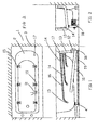
- FIGs. 1 to 3 illustrate a whirlpool bath assembly identified generally by the reference numeral 1 comprising a whirlpool assembly according to the invention mounted on a bath 2.
- the bath 2 is illustrated mounted between the walls of a bathroom, identified by the reference numeral 3, and incorporates a conventional waste water drain 4.
- a suction pipe 10 incorporating a water suction inlet device feeds a water circulation pump 12 forming part of a water recirculation unit which in turn feeds a water manifold 13 and system feed pipes 14, each of which terminates in a venturi jet unit 15.
- Each venturi jet unit 15 is connected by further pipes 16 to air control means 17 mounted in the side wall of the bath 2.
- the pump 12 is connected through a self-cleaning pump drain-off valve 18 and waste-water pipe formed by a drain pipe 19 to the waste-water drain 4. It should be noted that there are no bends in any of the piping where waste water can lodge.
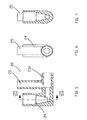
- the venturi jet unit 15 comprises a housing 20 secured to the bath 2 by clamping means formed by a clamp 21.
- the housing 20 is a two-part housing as can be seen from Figs. 5 and 15 and comprises an outer body portion 22 and an inner body portion 23 secured together by a suitable adhesive at 23a.
- the housing 20 comprises a water inlet 24 and an air inlet 25 communicating with a main conduit 26 so-configured as to form a venturi.
- the inner body portion 23 of the housing 20 has a threaded annular recess 27 for reception of the clamp 21 see Fig. 15.
- the water inlet 25 and conduit 26 combine to form an elongate bore between water supply inlet and outlet, the water inlet 25 having an elongate feeder bore substantially at right angles to a main bore formed by the conduit 26.
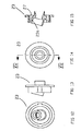
- the clamp 21 is illustrated and comprises a bored cap 28 having threads 29 for engagement with the threaded annular recess 27.
- the bored cap 28 has recesses 30 for ease of fixing by use of a suitable tool.
- the assembly of the venturi jet unit 15 will be readily easily understood.
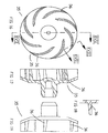
- a self-draining impeller indicated generally by the reference numeral 35 forming part of the water circulation pump 12.
- the impeller is a conventional centrifugal pump impeller, except that it has vanes 36 which are angled so as to let water run out of the pump.
- a self-cleaning drain-off valve 18 which comprises a valve body 40 having an upper inlet bore 41 which is in turn connected to the suction pipe 10 not shown in this Figure.
- the bore 41 is incorporated in a cap 42 housing an o-ring 43 and secured to the valve body 40 by a threaded ring 44.
- a lip 45 which projects into the interior of the valve body 40. Part of the lip is cut-away to form a drain channel 46.
- a valve disc 47 is slidably mounted within a sleeve 48 mounted within the valve body 40.
- the sleeve 48 incorporates an o-ring 49 and it will be noted that it is spaced apart from the bottom of the valve body 40.
- the valve disc 47 has a drain-off hole 50 and is spring biased upwards by a spring 51.
- the valve body 40 has a lower outlet bore 52.
- Any suitable control unit may be provided. There is nothing difficult or complex in providing the desired functionality. It is also envisaged that additionally a fan or blower may be provided.
- the pump may be set to continue to rotate for some preset time such as five minutes after the water has drained from the system.
- the fan if provided, may be operated when the control unit senses cessation of water flow in the system pipes. The fan may then be operated to deliver cold air through the system pipes and thus drive out any water retained on the surfaces of the assembly.
- any water still entrained within the pump will be delivered by centrifugal force over the impellers onto the side wall of the pump and then down into the drain off valve.
- the water is drawn by the water circulation pump 12 out the water suction inlet device 11 through the suction pipe 10 into the water manifold 13 where it is then distributed under pressure through the pipes 14 to the various venturi jet units 15.
- the amount of air entrained within the venturi jet unit 15 is controlled by the air control means 17.
- the self-cleaning drain-off valve 18 opens and any water in the pump 12 will be delivered out of the drain-off valve 18 as will any water in the suction pipe 10 and even in portion of the water manifold 13 which will drain back into the pump 12.
- the remainder of the water will drain out through the pipes 14 into the various venturi jet assemblies to be delivered into the bath and from thence out the bath drain 4.
- Fig. 20 the drain-off valve 18 is shown in the operating position i.e. in the position when the pump 12 is operating.
- the pressure will be such as to force the valve disc 47 downwards, thus seating the valve disc against the o-ring 49 in the sleeve 48. No water will then be delivered out the outlet bore 51.
- the pump is shut off there is no longer sufficient pressure to keep the valve disc 47 in the lowered position and the spring 50 will push the valve disc 47 upwards against the lip 45.
- any water gathering in the upper inlet bore 41 will bleed through the drain channel 46 and through the hole 50 into the valve body 40.
- venturi jet unit indicated generally by the reference numeral 60 in which parts similar to those described with reference to the previous drawings are identified by the same reference numerals.
- an elongated bore comprising a straight main bore 61 and a elongated feeder bore 62 having a water inlet 63 and an air duct 64.
- the main bore 61 is also enclosed by a ball-shaped outlet jet 65 adjacent the venturi outlet.
- the ball-shaped outlet jet 65 is of conventional construction and has a central passageway 66 which effectively forms an extension of the main bore 61 and thus of the total elongate bore.
- a downwardly directed drain-off channel 67 is provided between the main bore 61 and the bath.
- the mounting means for the venturi jet 60 comprises a collar 68a formed on the main body of the venturi jet unit 60 around the water supply outlet and a further collar 68 for mounting the main body against the valve side wall 2.
- a face plate 69a retains the ball-shaped outlet jet 65 and the collar 68 in position.
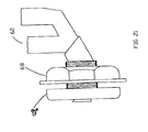
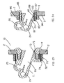
- venturi jet unit 70 comprises a housing 71 including an integral mounting collar 72 which circumscribes and is spaced apart from an internal tapered surface 73 of the main conduit 26. Both an external surface 74 and an internal surface 75 are threaded for engagement with a back nut 76 and a front collar 77.
- the venturi jet unit 70 is installed by loosely threading the back nut 76 on the external surface 74 of the mounting collar 72, before positioning the venturi housing 71 against the external surface of the bath 2 so that the main conduit 26 projects into the opening in the bath 2.
- the front collar 77 is then screwed into position as can be seen from Fig. 23.
- Silicone sealant can be used on appropriate surfaces and in particular on the external papered tapered surface 73.
- venturi jet unit 80 there is illustrated an alternative construction of venturi jet unit indicated generally by the reference numeral 80 in which parts similar to those described with reference to the previous drawings are identified by the same reference numerals.
- the venturi unit 80 has a venturi housing 81 which is externally threaded at 82.
- annular wall fitting 83 having a bath engaging collar 84 and a rearwardly projecting annular ring 85 which is threaded on both sides for engagement with the venturi housing 81 and the back nut 86 as can be seen from the drawing.
- the venturi housing 81 and the annular wall fitting 83 together combine to form a recess 87 in which is mounted an O-ring 88.
- the advantage of the two-part construction becomes apparent when it is desired to keep the outlet jet into the bath as small as possible.
- the water inlet and the air inlet should be of a reasonably substantial construction. If one is to provide a unitary construction then a problem arises in trying to fit the venturi jet unit into the bath. Indeed a hole larger than is necessary must be cut in the bath sidewall to accommodate the whole venturi jet unit when it is of a unitary construction.
- the two-part construction it is possible to clamp the first part of the venturi jet into position and then secure the inner body portion to the outer body portion by adhesive.
- the ideal size of face plate which is effectively the clamp should be of the order of 40 mm diameter.
- the extent of the elongate bore should be at least 30 mm and then if the inlets are to be of the order of 10 to 12 mm bore, it will be readily appreciated that such a unit could not be pushed through a hole in the bath which would be of sufficient small diameter to allow a face plate of 40 mm to be used.
- a hole cutter which is particularly suitable for metal baths such as cast iron or steel baths. This is designed for drilling holes in situ.
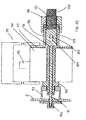
- the hole cutter indicated generally by the reference numeral 90, comprises a spindle 91 engaged within a pilot hole by a backing plate 91a and is concentric with and housed within a hole saw arbour 92 carrying a standard hole saw 93 driven by a transverse gear box 94 which in turn carries a power input shaft 95.
- the spindle 91 projects rearwardly into a tubular body member 96 having a flange 97 carrying the gear box 94 and also carrying a rotatable actuator 98 which is internally threaded.
- a thrust bearing 99 is interposed between the actuator 98 and the tubular body member 96.
- the spindle 91 carries an enlarged body portion 100 which is threaded at 101 and carries a knurled end knob 102 and is restrained from rotational movement within the tubular body member 96 by a transverse pin 103 within a slot 104.
- the drill attachment 9 which is particularly suitable for drilling cast iron or steel baths in situ could be used for any situation where holes were required in steel panels, etc. has already been described.
- a pilot hole is drilled in the bath wall 2 by a normal drill.
- the spindle 91 is then engaged within the backing plate 91a and the cutter is secured firmly in position.
- power for example through a hand drill, is applied to the power input shaft 95 and the hole saw arbour 92 is driven as is therefore the hole saw 93.
- the actuator 98 is rotated forcing the hole saw 93 into the bath 2 until the hole is cut, when the hole saw 93 will press against the backing plate 91a.
- the advantage of this particular method is that it always maintains the hole saw square against the hole.
- a particular advantage of the backing plate 91a is that it ensures that there will not be pressure on the saw and on the hole being cut to distort or damage the hole.
- Figs. 26 and 27 there is illustrated an alternative construction of spindle identified by the reference numeral 110.
- the spindle 110 is threaded at 111 and carries a nut 112.
- the spindle has a pair of longitudinally arranged wing members 113 pivotally connected to the spindle by pins 114 and spring biased outwards by springs 115.
- the wing members In operation to insert the spindle 110 into a hole, the wing members are placed flush along the spindle 110 as illustrated in Fig. 26. Immediately the wing members 113 pass through the pilot hole, the wing members 113 will pivot out as illustrated in Fig. 27.
- the nut 112 is then tightened down onto the workpiece identified by the reference numeral 116.
- any cutter blade could be used instead of a hole saw.
- the hole cutter has been illustrated as being an attachment for use with a drill, it could relatively easily combine its own drive means. This latter arrangement would be particularly suitable with the spindle illustrated in Figs. 26 and 27.
Landscapes
- Health & Medical Sciences (AREA)
- Public Health (AREA)
- Epidemiology (AREA)
- Pain & Pain Management (AREA)
- Physical Education & Sports Medicine (AREA)
- Rehabilitation Therapy (AREA)
- Life Sciences & Earth Sciences (AREA)
- Animal Behavior & Ethology (AREA)
- General Health & Medical Sciences (AREA)
- Veterinary Medicine (AREA)
- Percussion Or Vibration Massage (AREA)
- Drilling And Boring (AREA)
Applications Claiming Priority (4)
| Application Number | Priority Date | Filing Date | Title |
|---|---|---|---|
| IE970070 | 1997-02-05 | ||
| IE970070 | 1997-02-05 | ||
| IE970746 | 1997-10-14 | ||
| IE970746 | 1997-10-14 |
Publications (2)
| Publication Number | Publication Date |
|---|---|
| EP0875230A2 true EP0875230A2 (de) | 1998-11-04 |
| EP0875230A3 EP0875230A3 (de) | 2000-02-09 |
Family
ID=26320011
Family Applications (1)
| Application Number | Title | Priority Date | Filing Date |
|---|---|---|---|
| EP98650009A Withdrawn EP0875230A3 (de) | 1997-02-05 | 1998-02-05 | Whirlpoolanordnung |
Country Status (3)
| Country | Link |
|---|---|
| US (1) | US6052844A (de) |
| EP (1) | EP0875230A3 (de) |
| IE (2) | IES980076A2 (de) |
Cited By (4)
| Publication number | Priority date | Publication date | Assignee | Title |
|---|---|---|---|---|
| GB2349815A (en) * | 1999-03-11 | 2000-11-15 | Airbath Internat | Bath fitting to provide jets of air and/or water |
| EP1310228A1 (de) * | 2001-11-12 | 2003-05-14 | Eisl Sanitär Ges.m.b.H | Düse für Whirlpoolwannen |
| WO2005102246A1 (en) * | 2004-04-23 | 2005-11-03 | Masco Corporation | Self draining fitting for a whirlpool bath |
| WO2007033765A1 (de) | 2005-09-20 | 2007-03-29 | Palesta Anstalt | Zusammensetzung eines materials für badewannenlifter oder dessen bauteile |
Families Citing this family (18)
| Publication number | Priority date | Publication date | Assignee | Title |
|---|---|---|---|---|
| USD453207S1 (en) | 1999-12-02 | 2002-01-29 | John Pavlopoulos | Whirlpool bath tub |
| US6357060B2 (en) * | 2000-04-06 | 2002-03-19 | Cary Gloodt | Method and apparatus for purging water from a whirlpool system |
| US6859953B1 (en) | 2002-09-13 | 2005-03-01 | Steven E. Christensen | Jet propulsion system for spa or jetted bath using control of air draw to Venturi jets with a three-way air control valve |
| US20040168249A1 (en) * | 2003-02-28 | 2004-09-02 | Gerth Wilfried B. | Whirlpool bath jet assembly with drainage feature |
| CA2448139C (en) * | 2003-11-04 | 2011-03-29 | Maax Inc. | Method for mounting a recessed micro jet in a whirlpool bath and a kit therefor |
| US20050211612A1 (en) * | 2004-03-25 | 2005-09-29 | Mattson Roy W Jr | Water suction purification device |
| US7454802B2 (en) * | 2004-11-01 | 2008-11-25 | Acryline Usa, Inc. | Drain system for tub |
| US7950077B2 (en) * | 2005-12-05 | 2011-05-31 | Bowles Fluidics Corporation | Spa jet yielding increased air entrainment rates |
| US8220083B2 (en) * | 2006-11-24 | 2012-07-17 | Markon Holdings Limited | Mounting apparatus for bath fitting |
| US8549678B2 (en) * | 2007-05-07 | 2013-10-08 | Safety Tubs Company, Llc | Accelerated tub drain |
| US9775772B2 (en) | 2015-03-03 | 2017-10-03 | Kohler Co. | Whirlpool bathtub and purging system |
| US9903494B2 (en) | 2015-05-20 | 2018-02-27 | Jeffrey J. Prior | Liquid container leveler |
| RU2646573C2 (ru) * | 2016-03-02 | 2018-03-05 | Общество с ограниченной ответственностью Научно-внедренческое предприятие "ОРБИТА" (ООО НВП "ОРБИТА") | Ванна гидромассажная бесконтактная |
| WO2018152202A1 (en) * | 2017-02-14 | 2018-08-23 | Massachusetts Institute Of Technology | Systems and methods for automated microscopy |
| CN108685496A (zh) * | 2017-03-31 | 2018-10-23 | 太琦科技股份有限公司 | 按摩洗浴设备的自动管路清洗系统 |
| CN112138235A (zh) * | 2020-10-26 | 2020-12-29 | 杭州市余杭区妇幼保健院 | 一种医用坐浴器 |
| USD1052055S1 (en) | 2021-08-25 | 2024-11-19 | Onwai, LLC | Portable and collapsible shower |
| US11877966B2 (en) | 2021-08-25 | 2024-01-23 | Onwai, LLC | Personal hygienic shower, system, and method of use |
Citations (2)
| Publication number | Priority date | Publication date | Assignee | Title |
|---|---|---|---|---|
| EP0445504A1 (de) * | 1990-02-19 | 1991-09-11 | Ucosan B.V. | Whirlpoolwanne mit Wasserstrahldüse |
| AT397912B (de) * | 1991-12-23 | 1994-08-25 | Koller Rudolf | Düsenarmatur für wannen oder becken für sprudelbäder |
Family Cites Families (14)
| Publication number | Priority date | Publication date | Assignee | Title |
|---|---|---|---|---|
| US3890655A (en) * | 1973-08-27 | 1975-06-24 | Cleo D Mathis | Whirlpool jet for bathtubs |
| US4358862A (en) * | 1979-01-22 | 1982-11-16 | Thermasol, Ltd. | Connector assembly for whirlpool system |
| US4408721A (en) * | 1981-02-23 | 1983-10-11 | Jacuzzi Inc. | Fitting to combine air and pressurized water |
| GB2147523B (en) * | 1983-10-07 | 1986-09-03 | Bondwell Ltd | Hydrotherapy nozzle |
| US4542854A (en) * | 1983-10-27 | 1985-09-24 | Mathis Cleo D | Whirlpool jets |
| DE8416982U1 (de) * | 1984-06-02 | 1986-04-30 | Eberhard Hoesch & Söhne Metall und Kunststoffwerk GmbH & Co, 5166 Kreuzau | Wirbeldüsenwanne mit Systemvorspülung |
| US4586204A (en) * | 1984-09-24 | 1986-05-06 | Daniels Phillip D | Recirculating bathtub |
| GB8501174D0 (en) * | 1985-01-17 | 1985-02-20 | Heatons Bathrooms | Activated water baths |
| DE3768870D1 (de) * | 1986-07-07 | 1991-05-02 | Thomas Kurt Fraenninge | Verfahren und geraet zur reinigung der rohrleitungen einer badeanlage. |
| US4829607A (en) * | 1987-06-25 | 1989-05-16 | Donald W. Kern | Isolation system for a spa |
| GB8917882D0 (en) * | 1989-08-04 | 1989-09-20 | Ph Pool Services Ltd | Jet units for whirlpool-bath systems |
| GB9207635D0 (en) * | 1992-04-08 | 1992-05-27 | Bondwell Ltd | Hydro-therapy jet drainage |
| IT231978Y1 (it) * | 1993-09-27 | 1999-08-10 | Albatros System Spa | Raccordo idraulico per vasca da bagno, o simile |
| DE19631795C2 (de) * | 1996-08-07 | 1998-02-26 | Werner Dipl Ing Goedtner | Whirlpoolanlage mit einer Luftzufuhreinrichtung zu der Whirlpooldüse |
-
1998
- 1998-02-05 IE IE980076A patent/IES980076A2/en not_active IP Right Cessation
- 1998-02-05 IE IE980075 patent/IES79068B2/en not_active IP Right Cessation
- 1998-02-05 EP EP98650009A patent/EP0875230A3/de not_active Withdrawn
- 1998-02-05 US US09/018,944 patent/US6052844A/en not_active Expired - Fee Related
Patent Citations (2)
| Publication number | Priority date | Publication date | Assignee | Title |
|---|---|---|---|---|
| EP0445504A1 (de) * | 1990-02-19 | 1991-09-11 | Ucosan B.V. | Whirlpoolwanne mit Wasserstrahldüse |
| AT397912B (de) * | 1991-12-23 | 1994-08-25 | Koller Rudolf | Düsenarmatur für wannen oder becken für sprudelbäder |
Cited By (4)
| Publication number | Priority date | Publication date | Assignee | Title |
|---|---|---|---|---|
| GB2349815A (en) * | 1999-03-11 | 2000-11-15 | Airbath Internat | Bath fitting to provide jets of air and/or water |
| EP1310228A1 (de) * | 2001-11-12 | 2003-05-14 | Eisl Sanitär Ges.m.b.H | Düse für Whirlpoolwannen |
| WO2005102246A1 (en) * | 2004-04-23 | 2005-11-03 | Masco Corporation | Self draining fitting for a whirlpool bath |
| WO2007033765A1 (de) | 2005-09-20 | 2007-03-29 | Palesta Anstalt | Zusammensetzung eines materials für badewannenlifter oder dessen bauteile |
Also Published As
| Publication number | Publication date |
|---|---|
| IES80426B2 (en) | 1998-07-01 |
| US6052844A (en) | 2000-04-25 |
| IES980076A2 (en) | 1998-07-01 |
| EP0875230A3 (de) | 2000-02-09 |
| IES980075A2 (en) | 1998-04-08 |
| IES79068B2 (en) | 1998-04-08 |
| IE980074A1 (en) | 1998-08-12 |
Similar Documents
| Publication | Publication Date | Title |
|---|---|---|
| EP0875230A2 (de) | Whirlpoolanordnung | |
| US4715071A (en) | Hydrotherapy massage method and apparatus | |
| US5575424A (en) | Vacuum breaker for faucets | |
| US6301727B1 (en) | Modular tub spout assembly | |
| JPH01295085A (ja) | 比例式電動二方弁 | |
| US20090205122A1 (en) | Whirlpool tub and faucet/handheld shower combination | |
| US5518019A (en) | Diverter and volume control valve | |
| US4508137A (en) | Wall mountable vacuum breaker | |
| JP2554829B2 (ja) | 送水ヘッド | |
| CN105937261B (zh) | 卫生产品装置 | |
| US20040133975A1 (en) | Strainer in shower bath tap valve | |
| US5265287A (en) | Tap water powered shower water recirculation system | |
| IE84576B1 (en) | A whirlpool assembly | |
| US20070214563A1 (en) | Jet Assembly | |
| EP1116482B1 (de) | Venturistrahleinheit | |
| CN218542727U (zh) | 一种新型水泵及其泵体 | |
| KR200424181Y1 (ko) | 회전이 용이한 회전밸브가 결합된 벽체매립형 수전함의수전 결합구조 | |
| CN1668818A (zh) | 可防止回流的改进型坐浴装置 | |
| US20040168249A1 (en) | Whirlpool bath jet assembly with drainage feature | |
| US20040199993A1 (en) | Mounting structure for handheld showerhead | |
| US20250154750A1 (en) | Faucet | |
| US20060049633A1 (en) | Faucet anchor for interconnecting a faucet to the water supply | |
| US4719678A (en) | Method for draining a hydrotherapy pump | |
| US6779549B2 (en) | In-line vacuum breaker | |
| AU2024219935A1 (en) | Faucet |
Legal Events
| Date | Code | Title | Description |
|---|---|---|---|
| PUAI | Public reference made under article 153(3) epc to a published international application that has entered the european phase |
Free format text: ORIGINAL CODE: 0009012 |
|
| AK | Designated contracting states |
Kind code of ref document: A2 Designated state(s): AT BE CH DE DK ES FI FR GB GR IE IT LI NL PT SE |
|
| AX | Request for extension of the european patent |
Free format text: AL;LT;LV;MK;RO;SI |
|
| PUAL | Search report despatched |
Free format text: ORIGINAL CODE: 0009013 |
|
| AK | Designated contracting states |
Kind code of ref document: A3 Designated state(s): AT BE CH DE DK ES FI FR GB GR IE IT LI LU MC NL PT SE |
|
| AX | Request for extension of the european patent |
Free format text: AL;LT;LV;MK;RO;SI |
|
| K1C3 | Correction of patent application (complete document) published |
Effective date: 20000209 |
|
| RIN1 | Information on inventor provided before grant (corrected) |
Inventor name: HENNESSY, MICHAEL Inventor name: WALSH, MICHAEL PATRICK |
|
| 17P | Request for examination filed |
Effective date: 20000803 |
|
| AKX | Designation fees paid |
Free format text: AT BE CH DE DK ES FI FR GB GR IE IT LI NL PT SE |
|
| RAP1 | Party data changed (applicant data changed or rights of an application transferred) |
Owner name: FAISO LIMITED |
|
| 17Q | First examination report despatched |
Effective date: 20021022 |
|
| GRAP | Despatch of communication of intention to grant a patent |
Free format text: ORIGINAL CODE: EPIDOSNIGR1 |
|
| GRAP | Despatch of communication of intention to grant a patent |
Free format text: ORIGINAL CODE: EPIDOSNIGR1 |
|
| STAA | Information on the status of an ep patent application or granted ep patent |
Free format text: STATUS: THE APPLICATION IS DEEMED TO BE WITHDRAWN |
|
| 18D | Application deemed to be withdrawn |
Effective date: 20050913 |