EP0875256A1 - Canule d'irrigation et d'aspiration - Google Patents
Canule d'irrigation et d'aspiration Download PDFInfo
- Publication number
- EP0875256A1 EP0875256A1 EP98302200A EP98302200A EP0875256A1 EP 0875256 A1 EP0875256 A1 EP 0875256A1 EP 98302200 A EP98302200 A EP 98302200A EP 98302200 A EP98302200 A EP 98302200A EP 0875256 A1 EP0875256 A1 EP 0875256A1
- Authority
- EP
- European Patent Office
- Prior art keywords
- housing
- irrigation
- valve member
- cannula
- evacuation
- Prior art date
- Legal status (The legal status is an assumption and is not a legal conclusion. Google has not performed a legal analysis and makes no representation as to the accuracy of the status listed.)
- Granted
Links
- 230000002262 irrigation Effects 0.000 title claims abstract description 50
- 238000003973 irrigation Methods 0.000 title claims abstract description 50
- 239000012530 fluid Substances 0.000 claims abstract description 32
- 238000004891 communication Methods 0.000 claims description 5
- 230000001154 acute effect Effects 0.000 claims 1
- 230000008878 coupling Effects 0.000 claims 1
- 238000010168 coupling process Methods 0.000 claims 1
- 238000005859 coupling reaction Methods 0.000 claims 1
- 238000001356 surgical procedure Methods 0.000 description 5
- 238000002674 endoscopic surgery Methods 0.000 description 4
- 238000000034 method Methods 0.000 description 3
- 229920001971 elastomer Polymers 0.000 description 2
- 239000000806 elastomer Substances 0.000 description 2
- 238000012976 endoscopic surgical procedure Methods 0.000 description 2
- 239000000463 material Substances 0.000 description 2
- 241000531116 Blitum bonus-henricus Species 0.000 description 1
- 235000008645 Chenopodium bonus henricus Nutrition 0.000 description 1
- 239000004743 Polypropylene Substances 0.000 description 1
- 230000003187 abdominal effect Effects 0.000 description 1
- 210000003815 abdominal wall Anatomy 0.000 description 1
- 239000008280 blood Substances 0.000 description 1
- 210000004369 blood Anatomy 0.000 description 1
- 238000007796 conventional method Methods 0.000 description 1
- 238000013461 design Methods 0.000 description 1
- 210000005069 ears Anatomy 0.000 description 1
- 239000000835 fiber Substances 0.000 description 1
- 239000007789 gas Substances 0.000 description 1
- 239000011261 inert gas Substances 0.000 description 1
- 208000015181 infectious disease Diseases 0.000 description 1
- 238000002357 laparoscopic surgery Methods 0.000 description 1
- 238000002324 minimally invasive surgery Methods 0.000 description 1
- 238000012986 modification Methods 0.000 description 1
- 230000004048 modification Effects 0.000 description 1
- 238000002355 open surgical procedure Methods 0.000 description 1
- 239000004417 polycarbonate Substances 0.000 description 1
- 229920000515 polycarbonate Polymers 0.000 description 1
- -1 polypropylene Polymers 0.000 description 1
- 229920001155 polypropylene Polymers 0.000 description 1
- 230000001737 promoting effect Effects 0.000 description 1
Images

Classifications
-
- A—HUMAN NECESSITIES
- A61—MEDICAL OR VETERINARY SCIENCE; HYGIENE
- A61M—DEVICES FOR INTRODUCING MEDIA INTO, OR ONTO, THE BODY; DEVICES FOR TRANSDUCING BODY MEDIA OR FOR TAKING MEDIA FROM THE BODY; DEVICES FOR PRODUCING OR ENDING SLEEP OR STUPOR
- A61M1/00—Suction or pumping devices for medical purposes; Devices for carrying-off, for treatment of, or for carrying-over, body-liquids; Drainage systems
- A61M1/71—Suction drainage systems
- A61M1/77—Suction-irrigation systems
- A61M1/774—Handpieces specially adapted for providing suction as well as irrigation, either simultaneously or independently
-
- A—HUMAN NECESSITIES
- A61—MEDICAL OR VETERINARY SCIENCE; HYGIENE
- A61M—DEVICES FOR INTRODUCING MEDIA INTO, OR ONTO, THE BODY; DEVICES FOR TRANSDUCING BODY MEDIA OR FOR TAKING MEDIA FROM THE BODY; DEVICES FOR PRODUCING OR ENDING SLEEP OR STUPOR
- A61M1/00—Suction or pumping devices for medical purposes; Devices for carrying-off, for treatment of, or for carrying-over, body-liquids; Drainage systems
- A61M1/71—Suction drainage systems
- A61M1/74—Suction control
- A61M1/741—Suction control with means for varying suction manually
- A61M1/7413—Suction control with means for varying suction manually by changing the cross-section of the line
-
- A—HUMAN NECESSITIES
- A61—MEDICAL OR VETERINARY SCIENCE; HYGIENE
- A61M—DEVICES FOR INTRODUCING MEDIA INTO, OR ONTO, THE BODY; DEVICES FOR TRANSDUCING BODY MEDIA OR FOR TAKING MEDIA FROM THE BODY; DEVICES FOR PRODUCING OR ENDING SLEEP OR STUPOR
- A61M1/00—Suction or pumping devices for medical purposes; Devices for carrying-off, for treatment of, or for carrying-over, body-liquids; Drainage systems
- A61M1/71—Suction drainage systems
- A61M1/77—Suction-irrigation systems
- A61M1/772—Suction-irrigation systems operating alternately
Definitions
- the present invention relates generally to surgical instruments. More particularly, the present invention relates to cannulae and sleeves used to irrigate and evacuate body cavities during endoscopic or minimally invasive surgery.
- Endoscopic surgical procedures are becoming increasingly accepted in the medical community for many surgical procedures.
- endoscopic surgery a small incision typically is made in the abdominal wall through which a fiber optic viewing device (“endoscope”)is inserted into the abdominal of other body cavity.
- endoscope fiber optic viewing device
- Other small incisions are made through which surgical instruments are passed to dissect tissue and perform other operations.
- the body cavity is insufflated with an inert gas, such as C02, which provides space in which to manipulate surgical instruments and to view the area in which surgical operations are to take place.
- endoscopic procedures are preferable to many conventional surgical techniques because they are less invasive and therefore permit patients to recover more quickly and reduce the rate of infection.
- a device for simultaneously proving irrigation and evacuation that is adapted for single handed use. Nevertheless, a tube passes from the device, through a cannula or sleeve, and into the surgical Site. Irrigation and evacuation tubes have been combined into endoscopic cannulae or sleeves to combine previously separate apparatus into one. This cannula is passed through an incision and provides a tube through which suction may be applied to evacuate blood and other fluids from the surgical site and through which fluid may be provided to irrigate the surgical site.
- a cannula comprising a housing secured to a generally tubular sleeve member.
- the housing is provided with irrigation and evacuation fluid ports for connection to irrigation and evacuation conduits.
- An instrument port is formed in the housing and aligned with the sleeve member, wherein a surgical instrument can be inserted through the instrument port, housing, and sleeve member and into the bodily cavity.
- the instrument port includes seal members to seal against fluid leakage from the cannula with or without a surgical instrument passing through the housing and sleeve member.
- a valve member is rotatably carried by the housing to selectively obstruct one or more of the irrigation and evacuation ports. The valve is arranged such that the surgical instrument may remain in the housing and sleeve member during manipulation of the valve.
- a generally circular recess is provided in the housing to receive the valve member.
- the irrigation, evacuation, and instrument ports are arranged about the circumference of the circular recess.
- the valve member and recess cooperate to define a traverse, venturi shaped chamber within the housing.
- the instrument port includes both a lip seal and an outer diameter seal
- valve member is selectively removable from the housing.
- a fluid path extends from the instrument port, through the housing and venturi shaped chamber and the tubular sleeve member and is generally straight to provide improved fluid flow dynamics.
- a pair of seal members are disposed between the valve member and housing to seal the first and second fluid ports against fluid leakage.
- a switch member may be carried by the housing to cooperate with the valve member to selectively actuate a device external to the cannula, such as an irrigation or evacuation pump, responsive to movement of the valve member.
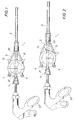
- Figures 1-3 are partial elevation views, partially in section, of the irrigation and evacuation cannula according to the present invention.
- Figure 4 is an exploded, side elevation view of the housing portion of the irrigation and evacuation cannula of Figures 1-3.
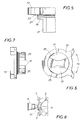
- Figure 5 is an enlarged, partial elevation view of a portion of the valve member illustrated in Figure 4.
- Figure 6 is a plan view of the valve member illustrated in Figures 1-5.
- Figure 7 is a side elevation view of the valve member of Figure 6.
- Figure 8 is a partial elevation view of a portion of the housing of the irrigation and evacuation cannula according to the preferred embodiment 6 of the present invention.
- FIGS 1-3 are partial elevation views, partially in section, of the irrigation and evacuation cannula 1 according to the present invention.
- Irrigation and evacuation cannula 1 comprises a generally tubular sleeve member 3 having a passageway or lumen extending therethrough.
- the sleeve member 3 is the portion of the cannula 1 that is inserted through an incision in a body wall to irrigate and evacuate a surgical site during endoscopic surgery.
- Sleeve member 3 is coupled to a housing 5 by threads, and an 0-ring (See Fig. 4) is provided to seal the joint against fluid loss.
- the housing 5 is provided with first and second or irrigation and evacuation ports 7 and 9 which are arranged generally opposite the sleeve member 3 and are angularly displaced less than 90° from the longitudinal axis of the cannula 1 .
- Irrigation and evacuation ports 7 and 9 are adapted for connection to the conduits of fluid supply (irrigation) and vacuum or suction (evacuation) apparatus (not shown).
- An instrument port 11 is provided in the housing 5 opposite from and aligned with the sleeve 3 .
- Instrument port 11 is provided with a conventional lip seal and outer diameter seal which cooperate to seal against fluid loss through port 11 whether a surgical instrument is present or not.
- an endoscopic surgical instrument 51 can be inserted through the instrument port 11 , then housing 5 , sleeve member 3 , and into the body cavity without loss of insufflation gas flowing through the cannula 1 .
- a valve member 13 is received for rotation in a circular recess 15 formed in the housing 5 .
- the hidden recess 15 is depicted in the phantom in Figures 1-3.
- the valve member 13 is formed to cooperate with the circular recess 15 in the housing 5 to define a venturi shaped chamber that is narrower or more restricted in its central region than at its periphery.
- the valve member 13 selectively obstructs irrigation and evacuation ports 7 and 9 which are in fluid communication with the circular recess 15 and sleeve member 3 .
- venturi shaped chamber defined by the valve member 13 and recess 15 permits selective obstruction of either or both of irrigation and evacuation ports 7 and 9 while a surgical instrument 51 extends through the housing 5 and sleeve member 3 even during manipulation of the valve 13 .
- FIGs 1-3 illustrate the irrigation and evacuation cannula 1 in three configurations, in each of which an endoscopic surgical instrument 51 extends through the instrument port 11 housing 5 , and sleeve member 3 .
- both irrigation and evacuation ports 7 and 9 are obstructed and closed by aligned portions of the valve member 13 and are scaled against fluid loss (the seals are described in greater detail with reference to Figure 6).
- the seals of the instrument port 11 prevent fluid loss around the instrument 51 .
- FIG. 2 illustrates the irrigation and evacuation cannula 1 in an irrigation mode in which the irrigation port 7 is open, while the evacuation port 9 is obstructed by the valve member 13 .
- irrigation fluid is introduced from an irrigation conduit (not shown) flowing through the irrigation port 7 , housing 5 , sleeve member 3 , and into the body cavity.
- Figure 3 depicts the irrigation and evacuation cannula 1 in an evacuation configuration in which the evacuation port 9 is open and the irrigation port 7 is obstructed by the valve member 13 .
- vacuum or suction is applied from an evacuation conduit (not shown) through the evacuation port 9 , then housing 5 , sleeve member 3 , and into the body cavity.
- Each of the configurations of Figures 1-3 is accomplished by rotating the valve member 13 relative to the housing 5 . Because of the configuration of the housing 5 and the valve member 13 , this rotation can occur without regard to the presence (or absence) of the surgical instrument 51 in the cannula 1 . Because the ports 7 and 9 are angularly displaced from the longitudinal axis of the cannula 1 , and due to the venturi shaped chamber defined by the valve 13 and housing 5 , the flow path that fluid must follow is generally straight and avoids right angle turns, thereby promoting more efficient fluid flow and providing fewer places for debris to be caught.
- Figures 4 and 5 are enlarged elevation views depicting the cooperation between the valve member 13 and circular recess 15 in the housing 5 .
- the valve member 13 includes a pair of projecting portions 17 that together are limited to a circular profile around the edge. Preferably, the two portions 17 cooperate to define a circle about 450m m in diameter.
- the circular perimeter is interrupted at the outside circular face by the ends of a transverse passage shown in Fig. 6 to permit flow.
- the valve member 13 is assembled into and rotatable within the circular recess 15 of the housing 5 . Venturi shaped chamber is defined between the portions 17 when enclosed within a circular recess 15 of the housing 5 .
- a circular shoulder 19 which includes an annular radial projection 21 , is provided on the valve member 13 .
- the shoulder 19 and radial projection 21 cooperate with corresponding recesses formed in the circular recess 15 of housing 5 to provide a "snap together" assembly that is easily assembled and disassembled.
- An 0-ring 23 is provided in the valve member 13 to seal the joint between the valve member 13 and the circular recess 15 against fluid loss.
- FIGS 6 and 7 are plan and elevation views of the valve member 13 according to the present invention.
- Each upstanding projection 17 is tapered as illustrated to define an included angle of about 60° at the inlet and outlet ends of the venturi shaped chamber.
- two seal members 25 are formed on the circular periphery, of the portions 17 .
- the seal members 25 preferably are formed of SantoprenetmTM, a polypropylene elastomer sold by Advanced Elastomer Systems of Akron, Ohio, which is of adequate thickness, preferably 1-2m m, to be compressed when the valve member 14 is assembled into the circular recess 15 of the housing 5 .
- Figures 1-3 As shown in Figures 1-3.
- seal members 25 are locate to seal against the irrigation and evacuation ports 7 and 9 when they are obstructed by the portions 17 of the valve member 13 .
- the exterior of the valve member 13 is provided with a pair of lugs or ears to enable hand gripping for a mechanical advantage to operate the valve member 13 rotating in the housing 5 .
- FIG 8 is a partial elevation view of the housing 5 of the irrigation and evacuation cannula 1 disclosing an additional embodiment of the present invention.
- the housing 5 is illustrated without the valve member 13 rotatably received within the circular recess 15 .
- a recesed microswitch 31 is embedded in the housing 5 beneath the flange (shown in Figures 1-3 and 6) carried by the valve member. Upon rotation of the valve member 13 , the flange toggles the microswitch 31 to actuate a suction or irrigation apparatus. Thus, first the suction and later the irrigation apparatus is automatically actuated depending upon the position of the valve member 13 relative to the housing 5 .
- the irrigation and evacuation cannula 1 is constructed of conventional materials for surgical instruments.
- the housing 5 , the sleeve member 3 and valve member 13 are formed of transparent or translucent polycarbonate to permit viewing of the surgical instrument 51 and fluid flow through cannula 11 in operation. All elastomeric seals are formed of conventional materials and the seals 25 are formed of the previously mentioned SantopreneTM.
- the irrigation and evacuation cannula according to the present invention provides a number of advantages.
- a principal advantage of the present invention is that it provides a cannula that is of simple design with relatively few moving parts.
- Another advantage is that fluid flows through the cannula in a relatively straight or linear fashion, avoiding the tortured flow paths provided in prior art cannulae. This renders the cannula according to the present invention more efficient in operation. more easily cleaned, and less prone to clogging.
- the invention also relates to a method of conducting endoscopic surgery comprising the steps of
Landscapes
- Health & Medical Sciences (AREA)
- Heart & Thoracic Surgery (AREA)
- Life Sciences & Earth Sciences (AREA)
- Animal Behavior & Ethology (AREA)
- Engineering & Computer Science (AREA)
- Anesthesiology (AREA)
- Biomedical Technology (AREA)
- Hematology (AREA)
- Pulmonology (AREA)
- Vascular Medicine (AREA)
- General Health & Medical Sciences (AREA)
- Public Health (AREA)
- Veterinary Medicine (AREA)
- Surgical Instruments (AREA)
- Media Introduction/Drainage Providing Device (AREA)
- External Artificial Organs (AREA)
- Endoscopes (AREA)
Applications Claiming Priority (2)
| Application Number | Priority Date | Filing Date | Title |
|---|---|---|---|
| US824849 | 1997-03-26 | ||
| US08/824,849 US5925013A (en) | 1997-03-26 | 1997-03-26 | Irrigation and evacuation cannula |
Publications (2)
| Publication Number | Publication Date |
|---|---|
| EP0875256A1 true EP0875256A1 (fr) | 1998-11-04 |
| EP0875256B1 EP0875256B1 (fr) | 2003-12-17 |
Family
ID=25242477
Family Applications (1)
| Application Number | Title | Priority Date | Filing Date |
|---|---|---|---|
| EP98302200A Expired - Lifetime EP0875256B1 (fr) | 1997-03-26 | 1998-03-24 | Canule d'irrigation et d'aspiration |
Country Status (5)
| Country | Link |
|---|---|
| US (1) | US5925013A (fr) |
| EP (1) | EP0875256B1 (fr) |
| JP (1) | JP3029598B2 (fr) |
| DE (1) | DE69820520T2 (fr) |
| WO (1) | WO1998042397A1 (fr) |
Cited By (4)
| Publication number | Priority date | Publication date | Assignee | Title |
|---|---|---|---|---|
| US9033929B2 (en) | 2008-04-28 | 2015-05-19 | Ethicon Endo-Surgery, Inc. | Fluid removal in a surgical access device |
| USD735852S1 (en) | 2008-04-28 | 2015-08-04 | Ethicon Endo-Surgery, Inc. | Fluid remover |
| USD736926S1 (en) | 2008-04-28 | 2015-08-18 | Ethicon Endo-Sugery, Inc. | Trocar housing |
| US11235111B2 (en) | 2008-04-28 | 2022-02-01 | Ethicon Llc | Surgical access device |
Families Citing this family (19)
| Publication number | Priority date | Publication date | Assignee | Title |
|---|---|---|---|---|
| EP1389458A1 (fr) * | 2001-04-27 | 2004-02-18 | Nagashima Medical Instruments Co., Ltd | Dispositif medical de rin age et d'aspiration |
| US7112177B2 (en) | 2003-03-04 | 2006-09-26 | Wolfe Tory Medical, Inc. | Apparatus for monitoring intra-abdominal pressure |
| US20060264995A1 (en) * | 2004-02-18 | 2006-11-23 | Fanton Gary S | Apparatus and methods for clearing obstructions from surgical cutting instruments |
| US20050182432A1 (en) * | 2004-02-18 | 2005-08-18 | Fanton Gary S. | Apparatus and methods for clearing obstructions from surgical cutting instruments |
| AU2004324086A1 (en) | 2004-10-11 | 2006-04-20 | Abviser Medical, Llc | Intra-abdominal pressure monitoring device and method |
| US20070119508A1 (en) * | 2005-11-29 | 2007-05-31 | West Richard L | Fluid Flow Diversion Valve and Blood Collection System Employing Same |
| US8690831B2 (en) | 2008-04-25 | 2014-04-08 | Ethicon Endo-Surgery, Inc. | Gas jet fluid removal in a trocar |
| US20090218535A1 (en) * | 2008-02-27 | 2009-09-03 | Andres Pasko | Flow controllers for fluid circuits |
| US8870747B2 (en) | 2008-04-28 | 2014-10-28 | Ethicon Endo-Surgery, Inc. | Scraping fluid removal in a surgical access device |
| US9358041B2 (en) | 2008-04-28 | 2016-06-07 | Ethicon Endo-Surgery, Llc | Wicking fluid management in a surgical access device |
| US8012129B2 (en) * | 2008-06-25 | 2011-09-06 | Tyco Healthcare Group Lp | Surgical portal apparatus with waffle seal |
| US20100234812A1 (en) * | 2009-03-11 | 2010-09-16 | Animal Innovations, Inc. | Fluid Recovery System |
| JP5735221B2 (ja) * | 2010-05-25 | 2015-06-17 | アクセスポイント テクノロジーズ有限会社 | カテーテル装置 |
| US9332998B2 (en) | 2012-08-13 | 2016-05-10 | Covidien Lp | Apparatus and methods for clot disruption and evacuation |
| US9332999B2 (en) | 2012-08-13 | 2016-05-10 | Covidien Lp | Apparatus and methods for clot disruption and evacuation |
| WO2014049826A1 (fr) * | 2012-09-28 | 2014-04-03 | テルモ株式会社 | Robinet d'arrêt médical |
| EP2996741B1 (fr) * | 2013-05-15 | 2021-02-24 | Becton, Dickinson and Company | Régulateurs de pression négative pour utilisation lors d'un prélèvement de sang |
| KR102430028B1 (ko) * | 2022-01-28 | 2022-08-11 | 유정선 | 외과 수술용 세척장치 |
| GB2639830A (en) * | 2024-03-22 | 2025-10-08 | Zethon Ltd | Bur irrigation system |
Citations (6)
| Publication number | Priority date | Publication date | Assignee | Title |
|---|---|---|---|---|
| US4668215A (en) | 1986-05-15 | 1987-05-26 | Dexide, Inc. | Irrigator-evacuator control for surgical procedures |
| US4696305A (en) | 1985-07-15 | 1987-09-29 | Peter von Berg Extrakorporale Systems-Medizintechnik GmbH | Flow controller |
| US4776840A (en) | 1987-09-28 | 1988-10-11 | Alteron, Inc. | Hand-held medical evacuator and irrigation device |
| US5244459A (en) * | 1992-01-28 | 1993-09-14 | Hill Raymond R | Suction irrigator endoscope |
| WO1993025139A1 (fr) * | 1992-06-18 | 1993-12-23 | Nikomed Aps | Instrument et ensemble a usage chirurgical |
| US5312373A (en) | 1991-02-19 | 1994-05-17 | Dexide, Inc. | Surgical endoscopic cannula with positive touch |
Family Cites Families (12)
| Publication number | Priority date | Publication date | Assignee | Title |
|---|---|---|---|---|
| US2964056A (en) * | 1957-05-13 | 1960-12-13 | Heinkel Ag Ernst | Three-way-delivery cock with automatic ventilation, especially for fuel |
| US3157201A (en) * | 1962-04-12 | 1964-11-17 | Cardiosonics Medical Instr Com | Fluid exchange valve |
| US4904245A (en) * | 1988-12-07 | 1990-02-27 | Allen S. Chen | Surgical valve assembly for urinary bladder irrigation and drainage |
| US5135026A (en) * | 1989-08-16 | 1992-08-04 | Manska Wayne E | Medical valve having fluid flow indicia |
| US4967797A (en) * | 1989-08-16 | 1990-11-06 | Manska Wayne E | Tap valve |
| US5573504A (en) * | 1990-01-26 | 1996-11-12 | C. R. Bard, Inc. | Composite irrigation and suction probe and valve |
| US5195958A (en) * | 1990-05-25 | 1993-03-23 | Phillips Edward H | Tool for laparoscopic surgery |
| US5197948A (en) * | 1991-01-03 | 1993-03-30 | Kamran Ghodsian | Intra-abdominal organ manipulator, irrigator and aspirator |
| AU656628B2 (en) * | 1991-10-18 | 1995-02-09 | United States Surgical Corporation | Endoscopic surgical instrument for aspiration and irrigation |
| US5314406A (en) * | 1992-10-09 | 1994-05-24 | Symbiosis Corporation | Endoscopic electrosurgical suction-irrigation instrument |
| US5348555A (en) * | 1993-04-26 | 1994-09-20 | Zinnanti William J | Endoscopic suction, irrigation and cautery instrument |
| US5496270A (en) * | 1994-09-26 | 1996-03-05 | Megadyne Medical Products, Inc. | Tri-tubular suction irrigation device |
-
1997
- 1997-03-26 US US08/824,849 patent/US5925013A/en not_active Expired - Lifetime
-
1998
- 1998-02-11 WO PCT/US1998/002647 patent/WO1998042397A1/fr not_active Ceased
- 1998-03-20 JP JP10072209A patent/JP3029598B2/ja not_active Expired - Fee Related
- 1998-03-24 DE DE69820520T patent/DE69820520T2/de not_active Expired - Lifetime
- 1998-03-24 EP EP98302200A patent/EP0875256B1/fr not_active Expired - Lifetime
Patent Citations (6)
| Publication number | Priority date | Publication date | Assignee | Title |
|---|---|---|---|---|
| US4696305A (en) | 1985-07-15 | 1987-09-29 | Peter von Berg Extrakorporale Systems-Medizintechnik GmbH | Flow controller |
| US4668215A (en) | 1986-05-15 | 1987-05-26 | Dexide, Inc. | Irrigator-evacuator control for surgical procedures |
| US4776840A (en) | 1987-09-28 | 1988-10-11 | Alteron, Inc. | Hand-held medical evacuator and irrigation device |
| US5312373A (en) | 1991-02-19 | 1994-05-17 | Dexide, Inc. | Surgical endoscopic cannula with positive touch |
| US5244459A (en) * | 1992-01-28 | 1993-09-14 | Hill Raymond R | Suction irrigator endoscope |
| WO1993025139A1 (fr) * | 1992-06-18 | 1993-12-23 | Nikomed Aps | Instrument et ensemble a usage chirurgical |
Cited By (5)
| Publication number | Priority date | Publication date | Assignee | Title |
|---|---|---|---|---|
| US9033929B2 (en) | 2008-04-28 | 2015-05-19 | Ethicon Endo-Surgery, Inc. | Fluid removal in a surgical access device |
| USD735852S1 (en) | 2008-04-28 | 2015-08-04 | Ethicon Endo-Surgery, Inc. | Fluid remover |
| USD736926S1 (en) | 2008-04-28 | 2015-08-18 | Ethicon Endo-Sugery, Inc. | Trocar housing |
| US9827383B2 (en) | 2008-04-28 | 2017-11-28 | Ethicon Llc | Surgical access device |
| US11235111B2 (en) | 2008-04-28 | 2022-02-01 | Ethicon Llc | Surgical access device |
Also Published As
| Publication number | Publication date |
|---|---|
| JPH10305104A (ja) | 1998-11-17 |
| DE69820520T2 (de) | 2004-09-30 |
| WO1998042397A1 (fr) | 1998-10-01 |
| JP3029598B2 (ja) | 2000-04-04 |
| EP0875256B1 (fr) | 2003-12-17 |
| DE69820520D1 (de) | 2004-01-29 |
| US5925013A (en) | 1999-07-20 |
Similar Documents
| Publication | Publication Date | Title |
|---|---|---|
| EP0875256B1 (fr) | Canule d'irrigation et d'aspiration | |
| US5244459A (en) | Suction irrigator endoscope | |
| US8915842B2 (en) | Methods and devices for maintaining visibility and providing irrigation and/or suction during surgical procedures | |
| US6168577B1 (en) | Directed stream blower for clearing a surgical site | |
| US5902264A (en) | Endoscopic surgical instrument for aspiration and irrigation | |
| EP0537573B1 (fr) | Instrument chirurgical endoscopique à aspiration et irrigation | |
| US11224733B2 (en) | Complex irrigation/suction flow path in a medical device | |
| US5364341A (en) | Irrigation/aspiration valve and probe for laparoscopy | |
| KR20190118680A (ko) | 내시경 수술 절차 중 기기의 엑세스를 허용하지 않으며 안정적인 공동 압력을 유지하기 위한 단일 루멘 가스 밀봉 투관침(trocar) | |
| EP2600759A1 (fr) | Systèmes et méthodes d'optimisation et de maintien de la visualisation d'un champ opératoire durant l'utilisation de laparoscopes chirurgicaux | |
| EP1208865B1 (fr) | Ensemble collecteur néonatal muni de valves | |
| US5605537A (en) | Endoscopic device | |
| CN114051569A (zh) | 内窥镜空气/水冲洗接头及方法 | |
| US20200205649A1 (en) | Endoscope unblocking flush system | |
| US5310406A (en) | Endoscopic aspirator surgical instrument | |
| KR20240036058A (ko) | 로봇 캐뉼라용 가스 밀봉 액세스 캡 및 로봇 보조 외과 시술을 수행하는 방법 | |
| EP3632293A2 (fr) | Dispositif d'accès à plusieurs lumières | |
| JP2025529166A (ja) | 外科用流体送達システム及びその構成要素 | |
| CA2497683C (fr) | Instrument chirurgical endoscopique servant a aspirer et a irriguer | |
| CN117729894A (zh) | 用于机器人套管的气体密封进入帽和执行机器人辅助外科手术的方法 |
Legal Events
| Date | Code | Title | Description |
|---|---|---|---|
| PUAI | Public reference made under article 153(3) epc to a published international application that has entered the european phase |
Free format text: ORIGINAL CODE: 0009012 |
|
| AK | Designated contracting states |
Kind code of ref document: A1 Designated state(s): DE FR GB IT |
|
| AX | Request for extension of the european patent |
Free format text: AL;LT;LV;MK;RO;SI |
|
| 17P | Request for examination filed |
Effective date: 19990503 |
|
| AKX | Designation fees paid |
Free format text: AT BE CH DE DK ES FI FR GB GR IE IT LI LU MC NL PT SE |
|
| AXX | Extension fees paid |
Free format text: AL;LT;LV;MK;RO;SI |
|
| R17P | Request for examination filed (corrected) |
Effective date: 19990429 |
|
| REG | Reference to a national code |
Ref country code: DE Ref legal event code: 8566 |
|
| RBV | Designated contracting states (corrected) |
Designated state(s): DE FR GB IT |
|
| RAP1 | Party data changed (applicant data changed or rights of an application transferred) |
Owner name: TYCO HEALTHCARE GROUP LP |
|
| 17Q | First examination report despatched |
Effective date: 20020920 |
|
| GRAH | Despatch of communication of intention to grant a patent |
Free format text: ORIGINAL CODE: EPIDOS IGRA |
|
| GRAS | Grant fee paid |
Free format text: ORIGINAL CODE: EPIDOSNIGR3 |
|
| GRAA | (expected) grant |
Free format text: ORIGINAL CODE: 0009210 |
|
| AK | Designated contracting states |
Kind code of ref document: B1 Designated state(s): DE FR GB IT |
|
| REG | Reference to a national code |
Ref country code: GB Ref legal event code: FG4D |
|
| REF | Corresponds to: |
Ref document number: 69820520 Country of ref document: DE Date of ref document: 20040129 Kind code of ref document: P |
|
| ET | Fr: translation filed | ||
| PLBE | No opposition filed within time limit |
Free format text: ORIGINAL CODE: 0009261 |
|
| STAA | Information on the status of an ep patent application or granted ep patent |
Free format text: STATUS: NO OPPOSITION FILED WITHIN TIME LIMIT |
|
| 26N | No opposition filed |
Effective date: 20040920 |
|
| PGFP | Annual fee paid to national office [announced via postgrant information from national office to epo] |
Ref country code: IT Payment date: 20120327 Year of fee payment: 15 |
|
| PG25 | Lapsed in a contracting state [announced via postgrant information from national office to epo] |
Ref country code: IT Free format text: LAPSE BECAUSE OF NON-PAYMENT OF DUE FEES Effective date: 20140324 |
|
| REG | Reference to a national code |
Ref country code: FR Ref legal event code: PLFP Year of fee payment: 19 |
|
| PGFP | Annual fee paid to national office [announced via postgrant information from national office to epo] |
Ref country code: DE Payment date: 20160218 Year of fee payment: 19 |
|
| PGFP | Annual fee paid to national office [announced via postgrant information from national office to epo] |
Ref country code: FR Payment date: 20160219 Year of fee payment: 19 Ref country code: GB Payment date: 20160223 Year of fee payment: 19 |
|
| REG | Reference to a national code |
Ref country code: DE Ref legal event code: R119 Ref document number: 69820520 Country of ref document: DE |
|
| GBPC | Gb: european patent ceased through non-payment of renewal fee |
Effective date: 20170324 |
|
| REG | Reference to a national code |
Ref country code: FR Ref legal event code: ST Effective date: 20171130 |
|
| PG25 | Lapsed in a contracting state [announced via postgrant information from national office to epo] |
Ref country code: DE Free format text: LAPSE BECAUSE OF NON-PAYMENT OF DUE FEES Effective date: 20171003 Ref country code: FR Free format text: LAPSE BECAUSE OF NON-PAYMENT OF DUE FEES Effective date: 20170331 |
|
| PG25 | Lapsed in a contracting state [announced via postgrant information from national office to epo] |
Ref country code: GB Free format text: LAPSE BECAUSE OF NON-PAYMENT OF DUE FEES Effective date: 20170324 |