EP0875259B1 - Füllvorrichtung eines Narkosemittelverdunsters - Google Patents
Füllvorrichtung eines Narkosemittelverdunsters Download PDFInfo
- Publication number
- EP0875259B1 EP0875259B1 EP98303128A EP98303128A EP0875259B1 EP 0875259 B1 EP0875259 B1 EP 0875259B1 EP 98303128 A EP98303128 A EP 98303128A EP 98303128 A EP98303128 A EP 98303128A EP 0875259 B1 EP0875259 B1 EP 0875259B1
- Authority
- EP
- European Patent Office
- Prior art keywords
- conduit
- closing
- filling
- arrangement
- liquid container
- Prior art date
- Legal status (The legal status is an assumption and is not a legal conclusion. Google has not performed a legal analysis and makes no representation as to the accuracy of the status listed.)
- Expired - Lifetime
Links
- 206010002091 Anaesthesia Diseases 0.000 title claims description 7
- 230000037005 anaesthesia Effects 0.000 title claims description 7
- 238000001949 anaesthesia Methods 0.000 title claims description 7
- 239000006200 vaporizer Substances 0.000 title claims description 6
- 239000007788 liquid Substances 0.000 claims description 31
- 230000003444 anaesthetic effect Effects 0.000 claims description 18
- 231100001261 hazardous Toxicity 0.000 claims description 2
- 239000012528 membrane Substances 0.000 description 7
- 229940124326 anaesthetic agent Drugs 0.000 description 3
- DPYMFVXJLLWWEU-UHFFFAOYSA-N desflurane Chemical compound FC(F)OC(F)C(F)(F)F DPYMFVXJLLWWEU-UHFFFAOYSA-N 0.000 description 3
- 229960003537 desflurane Drugs 0.000 description 3
- 239000003193 general anesthetic agent Substances 0.000 description 2
- 230000035939 shock Effects 0.000 description 2
- 239000000126 substance Substances 0.000 description 2
- 230000003247 decreasing effect Effects 0.000 description 1
- 239000011521 glass Substances 0.000 description 1
- 230000033001 locomotion Effects 0.000 description 1
- 230000007257 malfunction Effects 0.000 description 1
- 239000002184 metal Substances 0.000 description 1
- 238000011144 upstream manufacturing Methods 0.000 description 1
Images

Classifications
-
- A—HUMAN NECESSITIES
- A61—MEDICAL OR VETERINARY SCIENCE; HYGIENE
- A61M—DEVICES FOR INTRODUCING MEDIA INTO, OR ONTO, THE BODY; DEVICES FOR TRANSDUCING BODY MEDIA OR FOR TAKING MEDIA FROM THE BODY; DEVICES FOR PRODUCING OR ENDING SLEEP OR STUPOR
- A61M16/00—Devices for influencing the respiratory system of patients by gas treatment, e.g. ventilators; Tracheal tubes
- A61M16/10—Preparation of respiratory gases or vapours
- A61M16/14—Preparation of respiratory gases or vapours by mixing different fluids, one of them being in a liquid phase
- A61M16/18—Vaporising devices for anaesthetic preparations
- A61M16/183—Filling systems
Definitions
- Anaesthesia devices are used e.g. during operations in operating theatres in hospitals.
- the most essential components of an anaesthesia device are a vaporizer and a dosing device for anaesthetic. These components may be intergrated or separate, as in cassette-type structures.
- the main components of a vaporizer are a liquid container including a vapour generator, and a filling device.
- the filling device serves to supply and remove anaesthetic from the liquid container.
- Anaesthetic liquids are stored in transport and storage containers, or flasks, each anaesthetic liquid having a dedicated profile-coded flask opening. A flask can be connected only to a filling device suitable for each particular anaesthetic either directly or through a profile-coded adapter.
- anaesthetic liquid boils in room temperature, whereby the pressure inside the flask rises as the temperature rises.
- This anaesthetic liquid is desflurane. This is one of the reasons why the opening of a desflurane anaesthetic flask is provided with a profile-coded valve part.
- a tight filling conduit is provided between the flask and the valve of the filling device, and on inserting the flask opening deeper, the valves of the flask and the filling device are opened, the structure of the filling device determining the opening order, the number of valves, filling motions. etc.
- anaesthetic may flow from an overfilled liquid container to the dosing device, causing e.g. malfunction in' the entire anaesthesia device.
- DE-A-4022492 discloses a filling bottle for an anaesthetic agent which includes a temperature-sensitive closing device.
- the device is filled with a substance having a high coefficient of thermal expansion.
- the substance may be an anaesthetic agent.
- the device closes the bottle when a predetermined temperature and steam pressure is reached.
- the object of the invention is to provide an arrangement by means of which the prior art drawbacks can be eliminated.
- the object is to provide an arrangement by which the container cannot be filled or the filling is very slow if the pressure difference between the flask and the container is great.
- the filling device is provided with a closing means arranged in the liquid container, the closing means being adapted to close a filling conduit provided in the liquid container in response to pressure in the storage container exceeding a given pressure in the liquid container, thus preventing anaesthetic liquid from flowing to the liquid container.
- the main advantage of the invention is its simplicity, making the implementation and use of the invention advantageous. Owing to the simplicity, the arrangement of the invention also operates reliably. The arrangement of the invention also operates very efficiently, resulting in a still improved total safety in anaesthesia.
- Figure 1 to 3 show a schematic simplified form of the arrangement of the invention.
- Figure 1 shows the arrangement of the invention in a normal filling situation, i.e a situation where the difference between a pressure P of a transport and storage container 1, or flask, and a pressure P 1 of a liquid container 2 is very small.
- the flask 1 is placed tightly to a filling device la.
- the pressure of the flask 1 is allowed to be discharged to the container 2 causing only a small pressure shock to a closing means 3, 5.
- the filling conduit 4 can be formed of a plurality of pipes with a small diameter as is shown in Figure 2.
- this is a closed system, i.e. if liquid flows from the flask to the container, a corresponding amount of replenishment gas has to be conveyed from the container to the flask.
- a flow conduit has to be provided for the replenishment gas.
- some pipes also serve as a flow conduit for replenishment gas.
- the closing valve 3 is disposed in the closing conduit 5 whose volume is smaller than that of the filling conduit 4. It must be noted that the filling conduit 4 is considered to start from the juncture of the closing conduit 5. The length of the closing conduit may naturally vary.
- the closing valve 3 is in the vicinity of the outlet of the filling conduit in Figures 1 to 3, faces it in the example of Figures 1 and 3, the closing valve being opposite the outlet of the filling conduit 4 at a small distance from it.
- the closing valve is in a non-pressurized initial position, i.e. a position in which the outlet of the flow conduit 4 and the flow opening in the replenishment gas container 2 are open. It is to be noted that said conduits and flow openings can be the same as has been specified above.
- Figure 3 shows the arrangement of Figure 1 in a situation where the difference between the pressure P+ in the flask 1 and the pressure P, in the container 2 is great.
- the pressure of the flask is allowed to be discharged into the filling conduit 4 and the closing conduit 5.
- the volume of the closing conduit 5 is smaller than the volume of the filling 4
- the pressure shock reaches the side of the closing valve 3 facing the closing conduit 5 earlier than the side facing the filling conduit 4, the closing valve 3 moving from said initial position to a position closing the filling conduit 4.
- the closing valve 3 closes the end of the filling conduit by pressing against the end of the filling conduit as is shown in Figure 3.
- the flask 1 is being turned, the liquid cannot flow to the container 2.
- a flow resistance is further arranged to the filling conduit 4 behind the branching point of the closing conduit 5. Said flow resistance is provided by forming the filling conduit 4 with a plurality of pipes having a small diameter, the pipes causing the flow to throttle. It is obvious that the flow resistance can also be provided by arranging a throttle point to the conduit by narrowing the conduit etc. The flow resistance ensures that overpressure is discharged through the closing means 3, 5 in the above described manner.
- the closed filling conduit 4 opens when filling is restarted by using a flask that is cold or at room temperature, since the overpressure in the conduit is allowed to get stabilized into a cool flask.
- the closing valve 3 is arranged to return to the initial position from the position which closes the filling conduit 4.
- the replenishment gas conduit naturally also opens.
- the opening of the closing valve 3 can be sped up e.g. by designing the valve that closes the conduit such that there is no absolute tightening but instead a small leakage, and a return spring 6 and/or some other similar mechanism open the conduit automatically.
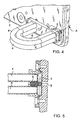
- FIG. 4 and 5 A simple closing valve is achieved e.g. by the solution of Figures 4 and 5.
- Figures 4 and 5 the same reference numerals are used for points corresponding to those in Figures 1 to 3.
- Figures 4 and 5 show an application in which the closing valve is placed at the end of an arched filling pipe structure that prevents overfilling and a wrong filling position. However, it is obvious that the closing valve can also be placed into a filling system that lacks said safety solution.
- Figure 4 shows only one wall of the container 2 for the sake of clarity. However, it is obvious that in an actual device the filling pipe structure of Figure 4 is placed inside the container 2 according to the principle shown in Figures 1 to 3.
- the closing valve is formed of an elastic membrane part 3 serving as the actual closing part and of the return spring 6. It is obvious that the membrane part 3 can also be formed such that the membrane part itself also operates as the return spring.
- the membrane part 3 is shown in an initial position, i.e. in a position corresponding to the situation in Figure 1.
- Figure 4 also shows with dashed lines the membrane part in a position where it shuts the filling conduit.
- the position of the membrane part 3 shown with dashed lines corresponds to the situation of Figure 3. It is advantageous to dimension the closing valve such that its area on which the pressure is acting on the side where overpressure is effective, i.e.
- the closing valve can also be a structure based on a metal membrane or glass, or e.g. a piston type structure.
- FIG 3 shows the point where a relief valve 7 is arranged.
- the relief valve is placed in flow communication with the closing conduit 5, but it is obvious that the relief valve can also be placed somewhere else, e.g. in association with the closing valve.
- Hazardous pressures are discharged by means of the relief valve 7 to the outside of the device.
- the opening pressure of the relief valve 7 can naturally be arranged according to the need.
- the type of the relief valve 7 can be any known solution.
- the closing conduit 5 is in flow communication substantially only with the space which is able to transfer the pressure of the flask 1 to the closing valve 3.
- the closing conduit is preferably connected to the filling conduit 4 or to a point which can be upstream from the filling conduit all the way to the flask 1.
- Utilizing a closing conduit is, however, not the only choice, but the invention may also be applied by forming the closing means using a closing valve. Such an application can be described as follows. As has been stated above, the length of the closing conduit may vary.
- the length of the closing conduit 5 is decreased, the limit being a solution in which the length of the closing conduit 5 is zero.
- the outlet of the filling conduit 4 has to be placed similarly such that it is located close to the closing valve 3 in accordance with the basic principle shown in Figures 1 and 3.
- the outlet can be placed in the above described manner by extending the filling pipe such that the outlet is disposed close to the branching point of the closing conduit shown in Figures 1 and 3.
- the closing valve 3 operates in the same way as in the above described examples.
- the part of the closing valve which is subjected to overpressure may also be a part different from the part closing the flow conduit.
- a connection has to be provided between said parts.
- Said parts can be formed of e.g. piston elements and a mechanical connection be provided between them.
- the connection may also be electrical.
- the closing means may also be provided by the overpressure affecting a sensor which in turn controls a means closing the filling conduit. The sensor can naturally be adjusted to issue a closing command after a given exceeding of the pressure limit etc.
Landscapes
- Health & Medical Sciences (AREA)
- Anesthesiology (AREA)
- Emergency Medicine (AREA)
- Pulmonology (AREA)
- Engineering & Computer Science (AREA)
- Biomedical Technology (AREA)
- Heart & Thoracic Surgery (AREA)
- Hematology (AREA)
- Life Sciences & Earth Sciences (AREA)
- Animal Behavior & Ethology (AREA)
- General Health & Medical Sciences (AREA)
- Public Health (AREA)
- Veterinary Medicine (AREA)
- Filling Or Discharging Of Gas Storage Vessels (AREA)
- Feeding, Discharge, Calcimining, Fusing, And Gas-Generation Devices (AREA)
Claims (9)
- Einrichtung in einem Anästhesie-Verdampfer, aufweisend einen Flüssigkeitsbehälter (2) mit einer Dampferzeugungseinrichtung; eine Füllvorrichtung (1a); Leitungen zum Zuführen eines Anästhetikums von einem Transport- und Lagerbehälter (1) an den Flüssigkeitsbehälter und/oder zum Abführen des Anästhetikums von dem Flüssigkeitsbehälter und zum Fördern einer der Menge an Anästhesie-Flüssigkeit entsprechenden Menge von Rückführgas von dem Flüssigkeitsbehälter zu dem Transportund Lagerbehälter aufgrund eines Befüllens des Behälters und/oder umgekehrt aufgrund einer Entleerung, und eine Rückführgasleitung zwischen dem Flüssigkeitsbehälter (2) und dem Transport- und Lagerbehälter (1),
dadurch gekennzeichnet, dass die Füllvorrichtung (1a) mit einer Schließvorrichtung (3, 5) versehen ist, die in dem Flüssigkeitsbehälter (2) angeordnet ist, wobei die Schließvorrichtung (3, 5) dazu bestimmt ist, eine in dem Flüssigkeitsbehälter (2) vorgesehene Befüll-Leitung (4) in Antwort auf den Druck in dem Lagerbehälter (1) zu schließen, der einen gegebenen Druck in dem Flüssigkeitsbehälter (2) übersteigt, womit verhindert wird, dass die Anästhesie-Flüssigkeit an den Flüssigkeitsbehälter (2) strömt. - Einrichtung nach Anspruch 1,
dadurch gekennzeichnet, dass die Schließvorrichtung aus einem Schließventil (3), das in der Nähe des Auslasses der Befüll-Leitung (4) angeordnet ist, und einer Strömungsöfmung für Rückführgas innerhalb des Flüssigkeitsbehälters (2) gebildet ist, und dass das Schließventil (3) durch den von dem Transport- und Lagerbehälter (1) für das Anästhetikum abgegebenen Druck dazu bestimmt ist, in eine Position bewegt zu werden, in der diese Leitungen gesperrt sind. - Einrichtung nach Anspruch 1,
dadurch gekennzeichnet, dass die Schließvorrichtung aus einer Schließleitung (5), die kleiner als das Volumen der Befüll-Leitung (4) ist, und aus einem Schließventil (3), das an deren Ende in der Nähe des Auslasses der Befüll-Leitung (4) angeordnet ist, und aus der Strömungsöffnung für das Nachfüllgas innerhalb des Flüssigkeitsbehälters gebildet ist, und dass das Schließventil (3) durch den von dem Transport- und Lagerbehälter (1) für das Anästhetikum abgegebenen Druck dazu bestimmt ist, das Schließventil in eine Position zu bewegen, in der diese Leitungen gesperrt sind. - Einrichtung nach Anspruch 3,
dadurch gekennzeichnet, dass ein Strömungswiderstand in der Befüll-Leitung (4) nach dem Abzweigpunkt der Schließleitung (5) vorgesehen ist. - Einrichtung nach einem der Ansprüche 2 bis 4,
dadurch gekennzeichnet, dass das Schließventil (3) bei Abfallen des Drucks dazu bestimmt ist, in die Ruhelage zurückzukehren, in der die Befüll-Leitung und die Rückführgasleitung offen sind. - Einrichtung nach Anspruch 5,
dadurch gekennzeichnet, dass das Schließventil (3) so dimensioniert ist, dass dessen Bereich auf derjenigen Seite, wo der Überdruck wirkt, größer ist als der entsprechende Bereich auf der Seite der Befüll-Leitung (4). - Einrichtung nach einem der Ansprüche 2 bis 6,
dadurch gekennzeichnet, dass das Schließventil (3) in Verbindung mit einem Sicherheitsmechanismus angeordnet ist, der an dem Ende der Befüll-Leitung (4) angeordnet ist, um eine Überfüllung und eine falsche Füllposition zu verhindern. - Einrichtung nach einem der Ansprüche 1 bis 7,
dadurch gekennzeichnet, dass ein Entlastungsventil (7), das vorgesehen ist, um einen für einen Patienten schädlichen Druck von der Einrichtung fernzuhalten, in Verbindung mit der Schließvorrichtung (3, 5) versetzt (angeordnet) ist. - Einrichtung nach Anspruch 8,
dadurch gekennzeichnet, dass das Entlastungsventil (7) in Strömungsverbindung mit der Schließleitung (5) angeordnet ist.
Applications Claiming Priority (2)
| Application Number | Priority Date | Filing Date | Title |
|---|---|---|---|
| FI971898 | 1997-05-02 | ||
| FI971898A FI101860B1 (fi) | 1997-05-02 | 1997-05-02 | Sovitelma anestesiahöyrystimen yhteydessä |
Publications (3)
| Publication Number | Publication Date |
|---|---|
| EP0875259A2 EP0875259A2 (de) | 1998-11-04 |
| EP0875259A3 EP0875259A3 (de) | 1999-09-15 |
| EP0875259B1 true EP0875259B1 (de) | 2003-08-27 |
Family
ID=8548779
Family Applications (1)
| Application Number | Title | Priority Date | Filing Date |
|---|---|---|---|
| EP98303128A Expired - Lifetime EP0875259B1 (de) | 1997-05-02 | 1998-04-23 | Füllvorrichtung eines Narkosemittelverdunsters |
Country Status (5)
| Country | Link |
|---|---|
| US (1) | US6138672A (de) |
| EP (1) | EP0875259B1 (de) |
| JP (1) | JP4191279B2 (de) |
| DE (1) | DE69817436T2 (de) |
| FI (1) | FI101860B1 (de) |
Families Citing this family (16)
| Publication number | Priority date | Publication date | Assignee | Title |
|---|---|---|---|---|
| FR2817757B1 (fr) * | 2000-12-09 | 2004-09-03 | Draeger Medical Ag | Dispositif d'alimentation en anesthesique d'un appareil medical |
| US6745800B1 (en) | 2003-09-04 | 2004-06-08 | Datex-Ohmeda, Inc. | Arrangement for preventing overfill of anesthetic liquid |
| US6997184B2 (en) * | 2004-04-19 | 2006-02-14 | Donohue Timothy J | Cool air inhaler |
| US8522839B2 (en) * | 2006-03-06 | 2013-09-03 | Baxter International Inc. | Adapters for use with an anesthetic vaporizer |
| US7886780B2 (en) * | 2007-03-30 | 2011-02-15 | General Electric Company | Method and apparatus for preventing drug reservoir overfill |
| WO2008151667A1 (en) * | 2007-06-13 | 2008-12-18 | Maquet Critical Care Ab | A safety system for a breathing apparatus for delivering an anesthetic agent |
| US20090056716A1 (en) * | 2007-09-04 | 2009-03-05 | Atlantic Research Group Llc | Cool air inhaler and methods of treatment using same |
| US8534328B2 (en) * | 2008-04-09 | 2013-09-17 | Baxter International Inc. | Adapters for use with an anesthetic vaporizer |
| US8267081B2 (en) | 2009-02-20 | 2012-09-18 | Baxter International Inc. | Inhaled anesthetic agent therapy and delivery system |
| US8500088B2 (en) * | 2009-05-20 | 2013-08-06 | Baxter International Inc. | Container and pharmaceutical product |
| US9061114B2 (en) | 2011-11-23 | 2015-06-23 | General Electric Company | Vaporizer filler and method of filling a vaporizer |
| US10039895B2 (en) | 2013-03-06 | 2018-08-07 | Satori Innovations Corporation | Thermal material nebulizing system |
| US11077268B2 (en) | 2017-10-25 | 2021-08-03 | General Electric Company | Anesthesia vaporizer reservoir and system |
| US11027088B2 (en) | 2019-01-04 | 2021-06-08 | General Electric Company | Neonatal incubator humidifier system |
| US11759599B2 (en) * | 2020-06-26 | 2023-09-19 | GE Precision Healthcare LLC | Systems and method for valve control in a fill assembly of a medical device |
| DE102022115140A1 (de) * | 2021-06-24 | 2022-12-29 | Drägerwerk AG & Co. KGaA | Narkosemitteldosierer mit einer Einspeiseeinheit und einem Narkosemitteltank und Verfahren unter Verwendung eines Narkosemitteldosierers |
Family Cites Families (12)
| Publication number | Priority date | Publication date | Assignee | Title |
|---|---|---|---|---|
| US3536108A (en) * | 1968-01-24 | 1970-10-27 | Fraser Sweatman | Filling connection for a liquid receptacle |
| US4454893A (en) * | 1981-11-30 | 1984-06-19 | Puritan-Bennett Corp. | Low-noise diaphragm for use in exhalation valve |
| DE3544302C1 (de) * | 1985-12-14 | 1987-05-14 | Draegerwerk Ag | UEberlaufsicherung an einem Narkosemittelbehaelter |
| DE4022492C1 (de) * | 1990-07-14 | 1991-06-13 | Draegerwerk Ag, 2400 Luebeck, De | |
| DE4106758A1 (de) * | 1991-03-01 | 1992-09-03 | Draegerwerk Ag | Sicherheitsfuellvorrichtung fuer narkosemittelverdunster |
| DE4106906A1 (de) * | 1991-03-05 | 1992-09-10 | Draegerwerk Ag | Sicherheitsfuellvorrichtung fuer niedrigsiedende narkosemittel |
| US5419316A (en) * | 1991-08-21 | 1995-05-30 | Bernstein; Jerome | Anesthesia evaporators |
| GB2279016B (en) * | 1993-06-14 | 1997-04-09 | Blease Medical Equipment Limit | Vaporizer overfill safety device |
| US5427145A (en) * | 1993-10-07 | 1995-06-27 | Abbott Laboratories | Connector with integral valve |
| CA2110851C (en) * | 1993-12-07 | 2003-04-01 | Technimeca Medic (2002) Inc. | Device for preventing gas-lock during the transfer of a liquid in a closed system, an arrangement containing the same and a method of use |
| US5505236A (en) * | 1994-04-04 | 1996-04-09 | Abbott Laboratories | Anesthetic vaporizer filling system |
| US5509405A (en) * | 1994-11-21 | 1996-04-23 | Ohmeda Inc. | Pump flow vaporizer |
-
1997
- 1997-05-02 FI FI971898A patent/FI101860B1/fi not_active IP Right Cessation
-
1998
- 1998-04-21 US US09/063,598 patent/US6138672A/en not_active Expired - Fee Related
- 1998-04-23 DE DE69817436T patent/DE69817436T2/de not_active Expired - Lifetime
- 1998-04-23 EP EP98303128A patent/EP0875259B1/de not_active Expired - Lifetime
- 1998-05-01 JP JP12218698A patent/JP4191279B2/ja not_active Expired - Fee Related
Also Published As
| Publication number | Publication date |
|---|---|
| FI101860B (fi) | 1998-09-15 |
| DE69817436T2 (de) | 2004-03-11 |
| FI101860B1 (fi) | 1998-09-15 |
| FI971898A0 (fi) | 1997-05-02 |
| JPH10314310A (ja) | 1998-12-02 |
| JP4191279B2 (ja) | 2008-12-03 |
| DE69817436D1 (de) | 2003-10-02 |
| EP0875259A2 (de) | 1998-11-04 |
| EP0875259A3 (de) | 1999-09-15 |
| US6138672A (en) | 2000-10-31 |
Similar Documents
| Publication | Publication Date | Title |
|---|---|---|
| US6138672A (en) | Arrangement in anesthesia vaporizer | |
| KR100198205B1 (ko) | 액체 마취제용 컨테이너 | |
| EP2149006B1 (de) | Speicherbehälter für ein kryogenes fluid mit einem abgetrennten kryogenraum | |
| US6026841A (en) | Pressurized fluid apparatus | |
| US8403000B2 (en) | Assembly and system for tank filling, withdrawal and pressure management of a cryogenic liquid | |
| US5617906A (en) | Container for anaesthetic agent | |
| EP1663848B1 (de) | Wasserkühleradapter | |
| US5685159A (en) | Method and system for storing cold liquid | |
| BR0300327A (pt) | Sistema e método para controlar fluxo de combustìvel lìquido e vapor | |
| JPH10314310A5 (de) | ||
| JPH04241876A (ja) | 温度感応式の制御部材を有する、麻酔剤気化装置用の充填装置 | |
| US6745800B1 (en) | Arrangement for preventing overfill of anesthetic liquid | |
| FI104791B (fi) | Sovitelma anestesiahöyrystimen yhteydessä | |
| WO2008085005A1 (en) | Tank for holding a cryogenic liquid and a conduit assembly, and a system for effecting flow control and pressure management of a cryogenic liquid held in the tank | |
| CA2113845A1 (en) | Control system for filling tanks with saturated liquids | |
| EP0013579A2 (de) | Kopfstück für Flüssiggasbehälter | |
| CN105765280B (zh) | 用于调节环路中液体的系统 | |
| US11324913B2 (en) | Systems and methods for filling an anesthesia vaporizer using an ullage volume and vent | |
| CN105745479B (zh) | 用于调节环路中液体的系统 | |
| US5611375A (en) | Arrangement for overfill protection of a container for anaesthetic liquid | |
| PL177214B1 (pl) | Urządzenie do napełniania i opróżniania butli gazowej | |
| HU222723B1 (hu) | Szelep nyomás alatti folyadékáram szabályozására | |
| US20240044517A1 (en) | Expansion assembly and hot water tank | |
| EP0663614B1 (de) | Vorrichtung und Verfahren zum Übertragen von Flüssigkeiten | |
| KR200401656Y1 (ko) | 액체소화약제용 축압식소화기 |
Legal Events
| Date | Code | Title | Description |
|---|---|---|---|
| PUAI | Public reference made under article 153(3) epc to a published international application that has entered the european phase |
Free format text: ORIGINAL CODE: 0009012 |
|
| AK | Designated contracting states |
Kind code of ref document: A2 Designated state(s): DE FR GB IT NL SE |
|
| AX | Request for extension of the european patent |
Free format text: AL;LT;LV;MK;RO;SI |
|
| PUAL | Search report despatched |
Free format text: ORIGINAL CODE: 0009013 |
|
| AK | Designated contracting states |
Kind code of ref document: A3 Designated state(s): AT BE CH CY DE DK ES FI FR GB GR IE IT LI LU MC NL PT SE |
|
| AX | Request for extension of the european patent |
Free format text: AL;LT;LV;MK;RO;SI |
|
| 17P | Request for examination filed |
Effective date: 20000209 |
|
| AKX | Designation fees paid |
Free format text: DE FR GB IT NL SE |
|
| 17Q | First examination report despatched |
Effective date: 20020515 |
|
| GRAH | Despatch of communication of intention to grant a patent |
Free format text: ORIGINAL CODE: EPIDOS IGRA |
|
| RAP1 | Party data changed (applicant data changed or rights of an application transferred) |
Owner name: INSTRUMENTARIUM OY |
|
| GRAH | Despatch of communication of intention to grant a patent |
Free format text: ORIGINAL CODE: EPIDOS IGRA |
|
| GRAA | (expected) grant |
Free format text: ORIGINAL CODE: 0009210 |
|
| RAP1 | Party data changed (applicant data changed or rights of an application transferred) |
Owner name: INSTRUMENTARIUM CORPORATION |
|
| REG | Reference to a national code |
Ref country code: SE Ref legal event code: TRGR |
|
| AK | Designated contracting states |
Designated state(s): DE FR GB IT NL SE |
|
| PG25 | Lapsed in a contracting state [announced via postgrant information from national office to epo] |
Ref country code: NL Free format text: LAPSE BECAUSE OF FAILURE TO SUBMIT A TRANSLATION OF THE DESCRIPTION OR TO PAY THE FEE WITHIN THE PRESCRIBED TIME-LIMIT Effective date: 20030827 Ref country code: IT Free format text: LAPSE BECAUSE OF FAILURE TO SUBMIT A TRANSLATION OF THE DESCRIPTION OR TO PAY THE FEE WITHIN THE PRESCRIBED TIME-LIMIT;WARNING: LAPSES OF ITALIAN PATENTS WITH EFFECTIVE DATE BEFORE 2007 MAY HAVE OCCURRED AT ANY TIME BEFORE 2007. THE CORRECT EFFECTIVE DATE MAY BE DIFFERENT FROM THE ONE RECORDED. Effective date: 20030827 Ref country code: FR Free format text: LAPSE BECAUSE OF FAILURE TO SUBMIT A TRANSLATION OF THE DESCRIPTION OR TO PAY THE FEE WITHIN THE PRESCRIBED TIME-LIMIT Effective date: 20030827 |
|
| REG | Reference to a national code |
Ref country code: GB Ref legal event code: FG4D |
|
| REF | Corresponds to: |
Ref document number: 69817436 Country of ref document: DE Date of ref document: 20031002 Kind code of ref document: P |
|
| NLV1 | Nl: lapsed or annulled due to failure to fulfill the requirements of art. 29p and 29m of the patents act | ||
| PLBE | No opposition filed within time limit |
Free format text: ORIGINAL CODE: 0009261 |
|
| STAA | Information on the status of an ep patent application or granted ep patent |
Free format text: STATUS: NO OPPOSITION FILED WITHIN TIME LIMIT |
|
| 26N | No opposition filed |
Effective date: 20040528 |
|
| EN | Fr: translation not filed | ||
| PGFP | Annual fee paid to national office [announced via postgrant information from national office to epo] |
Ref country code: DE Payment date: 20130429 Year of fee payment: 16 Ref country code: GB Payment date: 20130429 Year of fee payment: 16 Ref country code: SE Payment date: 20130429 Year of fee payment: 16 |
|
| REG | Reference to a national code |
Ref country code: DE Ref legal event code: R119 Ref document number: 69817436 Country of ref document: DE |
|
| REG | Reference to a national code |
Ref country code: SE Ref legal event code: EUG |
|
| GBPC | Gb: european patent ceased through non-payment of renewal fee |
Effective date: 20140423 |
|
| REG | Reference to a national code |
Ref country code: DE Ref legal event code: R119 Ref document number: 69817436 Country of ref document: DE Effective date: 20141101 |
|
| PG25 | Lapsed in a contracting state [announced via postgrant information from national office to epo] |
Ref country code: GB Free format text: LAPSE BECAUSE OF NON-PAYMENT OF DUE FEES Effective date: 20140423 Ref country code: SE Free format text: LAPSE BECAUSE OF NON-PAYMENT OF DUE FEES Effective date: 20140424 Ref country code: DE Free format text: LAPSE BECAUSE OF NON-PAYMENT OF DUE FEES Effective date: 20141101 |