EP0875312A1 - Verbesserungen in und in Bezug auf das Giessen - Google Patents
Verbesserungen in und in Bezug auf das Giessen Download PDFInfo
- Publication number
- EP0875312A1 EP0875312A1 EP98303457A EP98303457A EP0875312A1 EP 0875312 A1 EP0875312 A1 EP 0875312A1 EP 98303457 A EP98303457 A EP 98303457A EP 98303457 A EP98303457 A EP 98303457A EP 0875312 A1 EP0875312 A1 EP 0875312A1
- Authority
- EP
- European Patent Office
- Prior art keywords
- profile
- mould
- sides
- portions
- cross
- Prior art date
- Legal status (The legal status is an assumption and is not a legal conclusion. Google has not performed a legal analysis and makes no representation as to the accuracy of the status listed.)
- Withdrawn
Links
- 238000005266 casting Methods 0.000 title claims abstract description 30
- 230000007704 transition Effects 0.000 claims abstract description 17
- 238000000034 method Methods 0.000 claims description 7
- 239000000463 material Substances 0.000 claims description 4
- 239000012768 molten material Substances 0.000 claims description 3
- 239000002184 metal Substances 0.000 abstract description 14
- 230000008901 benefit Effects 0.000 abstract description 5
- 230000009467 reduction Effects 0.000 abstract description 2
- 239000000047 product Substances 0.000 description 12
- 230000002829 reductive effect Effects 0.000 description 8
- 230000008602 contraction Effects 0.000 description 7
- 238000001816 cooling Methods 0.000 description 7
- 230000008859 change Effects 0.000 description 3
- 230000005499 meniscus Effects 0.000 description 3
- 238000000926 separation method Methods 0.000 description 3
- 238000005452 bending Methods 0.000 description 2
- 229910003460 diamond Inorganic materials 0.000 description 2
- 239000010432 diamond Substances 0.000 description 2
- 238000005304 joining Methods 0.000 description 2
- 238000004519 manufacturing process Methods 0.000 description 2
- 230000015572 biosynthetic process Effects 0.000 description 1
- 239000006227 byproduct Substances 0.000 description 1
- 239000007795 chemical reaction product Substances 0.000 description 1
- 238000009749 continuous casting Methods 0.000 description 1
- 238000005336 cracking Methods 0.000 description 1
- 230000007423 decrease Effects 0.000 description 1
- 230000003247 decreasing effect Effects 0.000 description 1
- 230000000694 effects Effects 0.000 description 1
- 230000000670 limiting effect Effects 0.000 description 1
- 239000000155 melt Substances 0.000 description 1
- 230000036961 partial effect Effects 0.000 description 1
- 239000007787 solid Substances 0.000 description 1
- 230000003068 static effect Effects 0.000 description 1
Images


Classifications
-
- B—PERFORMING OPERATIONS; TRANSPORTING
- B22—CASTING; POWDER METALLURGY
- B22D—CASTING OF METALS; CASTING OF OTHER SUBSTANCES BY THE SAME PROCESSES OR DEVICES
- B22D11/00—Continuous casting of metals, i.e. casting in indefinite lengths
- B22D11/04—Continuous casting of metals, i.e. casting in indefinite lengths into open-ended moulds
-
- B—PERFORMING OPERATIONS; TRANSPORTING
- B22—CASTING; POWDER METALLURGY
- B22D—CASTING OF METALS; CASTING OF OTHER SUBSTANCES BY THE SAME PROCESSES OR DEVICES
- B22D1/00—Treatment of fused masses in the ladle or the supply runners before casting
Definitions
- This invention concerns improvements in and relating to casting, particularly, but not exclusively in relation to continuous casting of molten metal.
- Molten metal is frequently cast into billets and other cross sectional shapes in which the thickness and width of the material cross section are substantially similar by pouring into an open ended mould.
- the withdrawal of the part solidified metal is balanced against the input of molten metal.
- the metal is cooled to provide a solid shell by the time of its exit. During this cooling the metal cools and contracts giving rise to a reduced circumferential length.
- Shrinkage of the strand to a greater extent than the taper is almost inevitable in such circumstances. This feature is particularly problematical at the corners of square or rectangular cross-section moulds.
- the more flexible nature of the shell at the mid sections of the walls facilitates bending and continued contact with the mould wall due to ferro static pressure. At the corners, however, the shell tends to pull away so leading to reduced cooling.
- the reduced shell thickness provides a severe restriction on the rate of casting. Increasing the speed of casting above a limiting point risks shell rupture at this thinnest point, which usually terminates the casting operation.
- Moulds have been utilised with a non-linear taper, intended to more closely follow the strand contraction, however, the taper is difficult to calculate and excess taper leads to jamming.
- moulds employ an initial square cross-section followed by a transition to a concave form, a curved walled diamond. This technique also results in undesirable tensile strains in the shell or near the corners.
- a mould having a casting axis, a first cross-sectional profile being defined normal to a point on this axis and a second cross-sectional profile being defined normal to a further point on this axis, the second profile being nearer the mould outlet than the first, the second profile defining one or more corner angles between sides defining that profile, the first profile defining substantially equivalent corner angles for one or more equivalent corners to those in the second profile, the corner angles in the first profile being defined by proximate portions to that corner, the first profile having one or more portions which give it a different profile to the second profile.
- the mould accommodates the reduction in metal volume from first profile to second profile whilst maintaining contact between the shell and mould wall.
- the configuration of the proximate portions of the sides to the corners ensures that the transition through the mould is achieved without changing the corner portion of the shell.
- the casting axis may be linear. In such a case preferably the mould is substantially vertically aligned with the mould outlet below the mould inlet.
- the casting axis may be non-linear.
- the casting axis may define an arc, most preferably an arc of constant radius. In such a case it is preferred that the mould walls follow the axis.
- the mould walls perpendicular to the arc preferably follow arcs corresponding to the casting axis.
- the first profile preferably has a configuration different from an enlarged version of the second profile.
- the first profile is positioned within a part of the mould occupied by molten metal during casting.
- the second profile is positioned near the outlet from the mould.
- the second profile may be positioned at or near the outlet.
- transition surfaces are provided on each side of the mould extending from the first profile to the second profile.
- the transition surfaces may taper from the first to second profile at a constant rate, linear, or at a non-constant rate, for instance parabolic.
- the initial rate of taper from the first profile, toward the second profile may be higher than the subsequent rate.
- the proximate portion to proximate portion projected intersection angle is substantially that of the equivalent second profile corner angle throughout the transition.
- the corners of the mould are curved or chamfered, most preferably by a radius.
- the curve or radii extends between the proximate portion of one side and the proximate portion of the adjoining side.
- the radii of the corners in the second profile is less than or equal to the radii of the corners in the first profile.
- the sides of the second profile are linear, with curved portions optionally linking adjacent sides.
- Preferably opposing sides are parallel.
- all sides and/or opposing sides are of the same length. Both pairs of opposing sides may have the same length or one pair may have a different length to the other.
- the second profile may define a generally square, generally rectangular or generally octagonal profile.
- the cross section of the second profile has a maximum extent in one direction, the width, and a maximum extent in another direction perpendicular to the first, the thickness.
- the maximum thickness and / or maximum width of the cross section may be defined at the periphery of the profile or within the profile.
- the width and / or thickness may be, and preferably are, parallel to at least one wall of the profile.
- the width is the larger of the width and thickness extents.
- the ratio of the width to the thickness is less than 10:1, more preferably less than 8:1 and ideally less than 6:1.
- the width is less than 700mm, more preferably less than 600mm and ideally less than 400mm for rectangular profiles.
- the thickness is less than 500mm, more preferably less than 400mm and ideally less than 300mm for rectangular cross section profiles.
- the second profile may define a generally I shaped cross-section.
- the second profile may comprise opposing parallel sides at a first cross-sectional separation, together with a further pair of opposing parallel sides, preferably perpendicularly aligned to the first pair, and preferably separated by a distance less than the first pair, with the length of the sides preferably also being less than the separation of the first pair. It is preferred that the first and second pair of opposing parallel sides be joined by angled sides.
- the angled sides may comprise a first side substantially parallel to the second pair of sides and an angled side joining the mutually parallel sides.
- the maximum width is less than 1200mm, more preferably less than 1000mm and ideally less than 500mm.
- the thickness is less than 600mm, more preferably less than 400mm and ideally less than 250mm.
- the different profile portion arise from deviations from the linear sides and curved corners of the second profile forming sides.
- the different portion or portions of the first profile side or sides may extend towards and/or away from the projected position of the respective second profile side.
- Deviations towards the second profile may include indents or insets or inward bows.
- Deviations away from the second profile may include recesses or bulges or outward bows.
- the portions may extend within the projected position of the second profile. In such a case the portions could again be thought of as insets or indents.
- the different portion or portions may comprise or consist of one or both proximate portions of that side.
- the sides of the first profile may be formed of a proximate portion towards each end and an intermediate portion which deviates from being parallel to the corresponding side of the second profile.
- the proximate portions may further lead to a curved or radii portion on the other side to the intermediate portion.
- the proximate portions may correspond to the equivalent portion of the second profiles.
- a rectilinear profile preferably two, more preferably 3 and ideally all four of the sides are provided with different portions to the second profile.
- a multi sided profile for instance an octagonal profile or I beam shaped profile, for instance having eight and twelve sides respectively, two, four or more of the sides may be provided with different portions.
- One or more portions may be provided on any one side.
- Opposing pairs of sides may be provided with sides which are mirror images of each other.
- Opposing sides may have concave and/or convex portions.
- the concave and/or convex portions may be defined by curved parts of the profile or linear parts joined by a point or curved transition.
- Sides may be defined by one or more curves.
- the sides may be provided with one or more curves extending away from the core of the mould and/or one or more curves extending toward the core of the mould.
- Preferred side forms include sides with, one curved recess; one curved inset and one curved recess; 2 curved insets and 1 curved recess; 2 curved recesses and 1 curved inset; 2 curved insets; 2 curved recesses.
- the recessed form of one opposing pair is matched by the inset form of the other opposing pair.
- Opposing side pairs of 2 recesses and 1 inset matched with 2 inset and 1 recess, or of 2 recesses matched with 2 insets are preferred.
- the recessed form of one or more sides may be matched by the inset form of that side or sides. Sides with a matching inset and recess are preferred.
- the mould may provide a first profile provided with a, preferably curved, recess on each side, the recess being bounded on each end by a proximate portion.
- the proximate portions follow the profile of the corresponding portions of the second profile.
- a portion of one or more sides may be a mirror image of one or more other portions of the same side.
- the equivalence of corner angles is maintained for two or more and most preferably all of the corners of the profile.
- the angle between projected proximate portions is ideally equal to the corresponding angle in the second profile within manufacturing tolerances, in the first profile and most preferably throughout the transition from first to second profile. Benefits in reduced rotation, when compared with the prior art, can be obtained where the angle remains within ⁇ 5° or more preferably ⁇ 2° of the angle. For a right angle, angles of between 85° and 95° and more preferably between 88° and 92° may be provided.
- proximate portions may be taken directly where such portions contact one another. Where proximate portions are joined by curves, radii or other means, the projection of the proximate portions in the cross-sectional plane of the first profile is preferred to determine the angle.
- the mould is between 500 and 1200mm long, from inlet to outlet.
- the first profile is provided within the first 25% of the mould length.
- the second profile is provided within the last 25% of the mould length.
- the mould outlet may be of square or rectangular or octagonal or I beam cross-section.
- the circumference of the first profile is greater than that of the second profile by an amount which relates to the contraction of the strand shell within the mould, typically 1 to 2.5%.
- a side may be defined by the length from corner to corner. Where curved or radii corners are provided a side may be defined between the projected intersection of the adjacent proximate portions or between the mid point of one curve and the mid point of the curve at the other end of the side. Preferably the proximate portion of a side forms between 2 and 50% of that side, and more preferably between 5 and 30%. The radii or curve may form between 1 and 15% of a side, and more preferably between 2 and 10%. The non-linear portion of the side may form between 1 and 100% of that side, and more preferably between 50 and 100%.
- a side may be formed of between 5 and 15% curve or radii and between 85 and 95% proximate portion.
- a side may be formed of between 1 and 10% curve or radii, between 1 and 10% proximate portion and between 80 and 98% non-corresponding portion.
- a mould with an inlet and an outlet, a cross-sectional profile nearer the inlet having a greater circumferential length than a second cross-sectional profile nearer the outlet, the first cross-sectional profile deviating from the shape of the second cross-sectional profile and the first cross-sectional profile being defined by four sides the portions of which adjoining a corner or the portions of which adjoining a connecting curve when projected, meet at substantially 90°.
- a mould comprising a mould wall defining a through passage with an inlet and an outlet and having a first cross-sectional profile and a second cross-sectional profile, normal to the direction of casting, the second profile being nearer the outlet than the first profile, the profiles being defined by four sides connected at corners, the second profile being defined by substantially linear sides, the first profile being defined by one or more sides which comprise one or more portions which are non-parallel or non-concentric with the corresponding second profile side and in which for each side of the first profile, the proximate portion to a corner of a side defines an angle of substantially 90° with the proximate portion to that corner of the adjoining side, at their projected contact.
- the second and third aspects of the invention may include one or more of the features of options set out elsewhere in this application, including in the first aspect.
- a method of casting comprising feeding molten material to an inlet end of a mould and extracting partially solidified material from an outlet end of the mould, the mould having a casting axis, a first cross-sectional profile being defined normal to a point on this axis and a second cross-sectional profile being defined normally to a further point on this axis, the second profile being nearer the mould outlet than the first, the second profile defining one or more corner angles between sides defining that profile, the first profile defining substantially equivalent corner angles for one or more equivalent corners to those in the second profile, the corner angles in the first profile being defined by proximate portions to that corner, the first profile having one or more portions which give it a different profile to the second profile.
- a method of casting comprising feeding molten material to an inlet end of a mould and extracting partially solidified material from the outlet end of the mould, the mould comprising a mould wall defining a through passage with an inlet and an outlet and having a first cross-sectional profile and a second cross-sectional profile, normal to the direction of casting, the second profile being nearer the outlet than the first profile, the profiles being defined by four sides connected at corners, the second profile being defined by substantially linear sides, the first profile being defined by one or more sides which comprise one or more portions which are non-parallel or non-concentric with the corresponding second profile side and in which for each side of the first profile, the proximate portion to a corner of a side defines an angle of substantially 90° with the proximate portion to that corner of the adjoining side, at their projected contact
- the method of the fourth or fifth aspect may alternatively or additionally provide for the features according to the first, second and third aspects of the invention or described elsewhere within the application.
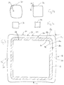
- Figure 1a shows a top plan view of a casting mould typical of the prior art used for casting billets and other cast products in which the width and thickness of the cross section are substantially similar.
- Billets and similar products such as blooms and beam blanks come in a variety of sizes from large blooms at up to 600mm by 400mm, medium blooms at up to 400mm x 300mm, small blooms / large billets at up to 250mm square, medium billets of 160mm to 100mm square and small billets of less than 100mm square.
- Such products also include I-section beams or beam blanks including large beam blanks of 1100mm x 500mm, down to small beam blanks of up to 500mm x 200mm (maximum dimensions).
- Billets and the other product types generally have a maximum width to maximum thickness of cross section ratio of less than 3:1 and more generally less than 2:1 or even less than 1.5:1.
- Billets, blooms and beam blanks contrast distinctly from slab type products in which the width of the product is very substantially greater than the thickness of the product.
- Slabs are typified by products such as 3000mm x 125mm, 2200mm x 250mm, 1800mm x 200mm, 1500mm x 50mm and 1200mm x 70mm cross-sections.
- the maximum width to maximum thickness ratio for such slab type products is, however, very great. In general, the value exceeds 9:1 and in many cases exceeds 15:1 or even 20:1. These products are not considered as products in which the width and thickness are substantially similar.
- the inner profile at the mould inlet 2 tapers along surface 4 to outlet profile 6 of reduced circumferential length.
- Figure 1a also illustrates a cross-section through the metal strand 8 near to the outlet of the mould.
- the gap 12 between the mould profile 6 and outer surface of the strand shell 10 is greatest in the corners due to the shell pulling away at the corners caused by circumferential contraction. Due to the increased gap, cooling at the corners is reduced so leading to a reduced shell thickness between the outer surface 10 and inner surface 14 of the solidified metal.
- the solidified shell provides the containment support for the molten core of the strand 8 once it leaves the confines of the mould. It is therefore imperative to achieve sufficient shell thickness to provide this containment. The quicker this can be achieved the faster the rate of casting which can be employed.
- Enhanced casting speeds offer improved productivity for a strand and also allow the number of strands which must be provided for to be decreased reducing capital costs.
- the mould profile illustrated in Figure 1b aims to maintain mould to shell contact throughout and provide control of the heat transfer rate.
- the mould has an initial profile 20 in which the walls are bulged away from a square cross-section, but the mould profile under goes a transition to a squared profile 22 towards the outlet.
- the shell forms at the interface between the melt and mould wall at the meniscus. Once formed the shell defines the strand and the shell thickens with further cooling. However, as the shell progresses down the mould it must bend to follow the changing profile of the mould. This bending occurs principally as a change in the corner angle in the corner areas 24. As the angle 26 between the adjoining wall portions decreases tensile strains arise within the shell. Any forces applied to the shell are undesirable as it is relatively fragile and prone to cracking.
- FIG. 1c An alternative mould form is shown in Figure 1c with a square cross-sectioned initial profile 30 which tapers most significantly at the middle portions of the walls, but also elsewhere, to give a concave diamond form profile 32.
- this mould gives rise to change in the corner angle during its passage, which as a consequence gives rise to undesirable tensile strains also.
- a first embodiment of the present invention is illustrated in Figure 2 as a sectioned side view.
- the mould has an overall length of between 500 and 1200mm between inlet end 46 and outlet end 47.
- the meniscus level 48 the level to which the molten metal is introduced in pouring, is generally some 100mm below the inlet end 46. Proceeding from the inlet end to the outlet end the mould passes from an inlet end profile 50 via transition surfaces 52 to an outlet end profile 54.
- the mould provides an inlet end profile 50 which tapers, following transition surfaces 52, to outlet end profile 54.
- Sides 56 of the inlet end profile are provided with bulges 58 and sides 60 of the inlet end are provided with insets or indents 62.
- Two opposing faces are thus concave, whilst the other pair are convex and the four corners are curved to provide a transition between each adjoining side the side joining at 90°.
- the outlet end of the mould has a square profile 64 defined by sides 66 68 which meet at 90°.
- Figure 4 illustrates a different mould with inlet end profile 100 and outlet end profile 102.
- Each side of the inlet end profile 100 is formed with a smoothly curved recess 104 and corresponding indent 106.
- the recess of one side contacts an indent of an adjoining side and vice versa. In this way the projected contact between any two sides is 90°.
- the contact between the sides is radiused in practice.
- the profile of the indented portions 106 of the inlet end profile 100 may lie within the outlet end profile 102, which is square in cross-section. More complex style mould shapes of this type also offer advantages in terms of greater resistance to distortion at the meniscus due to the stiffening effect of the curved sides. Enhanced mould life arises from this.
- Figure 5 illustrates a further alternative, once again with a square outlet end profile 150.
- the inlet end profile 152 is formed of four sides, one opposing pair of sides comprising a central indented portion 154 and two adjoining recessed portions 156, the other opposing pair ccmprising a central recessed portion 158 and two adjoining indented portions 160.
- the wave style curve defining the recesses and indents being generally smoothly curved in shape, but retaining the concept of 90° corner angles.
- Figure 6 provides an inlet end profile 170 with one pair of opposing sides having two recessed portions 172 and the other pair having two indented portions 174.
- the mid point of each side corresponds directly, in plan view, with the outlet end profile 176 at an equivalent point. This makes the mould easier to align with the theoretical strand pass-line.
- Figure 7 once again provides a square outlet end profile 200 within the projection of the inlet end profile 202.
- the inlet end profile 202 is formed of four sides each with a significant portion 204 recessed so as to prcvide for the larger volume needed at the inlet.
- the inlet profile 202 also includes corner radii 206. Between the radii 206 and recessed portions 204 are intermediate portions 208 which define an angle of 90°. In this way these portions ensure that the corners are not rotated in anyway as the strand proceeds through the mould.
- the moulds illustrated above present a linear axis along which the strand advances when inside the mould.
- the pass line 302 curves in making the transition from substantially vertical alignment 304 when in the mould to substantially horizontal alignment 306 when in the rollers 308.
- the pass line assumes a substantially linear axis once more through the rollers 308.
- the present invention also includes non-linear axis for strand advance within the mould. A commonly employed configuration relating to this is illustrated in Figure 9.
- the mould 350 is provided with a curved axis, pass line 352.
- the part solidified strand leaving the mould possesses a curve.
- the pass line continues its curve path 354 towards the straightener rollers 356, however, by the time it exits the rollers 356 it has assumed a linear pass line configuration 358.
- References to normal to the direction of casting may be taken to be normal to the axis at a or any particular point on that axis.
- Figure 10 illustrates an inlet profile 400 and an outlet profile 402 for an octagonal billet product.
- the maximum thickness value and maximum width value for such a product is considered across the centre of the billets cross section from intersection of a pair of faces on one side to the intersection of a pair of faces on the opposing side.
- the outlet profile 402 has corner angles of 135° and the projected angle 403 between the proximate portions 404 of the inlet profile 400 are angled substantially, and preferably exactly, the same. In this way, whilst the bulges 408 provided in the sides of the inlet profile 400 accommodate the strand volume used to account for the contraction during cooling, the corner angles 403 remain constant throughout the strands passage through the mould and no undesirable forces arise as a result.
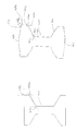
- Figure 11a illustrates an outlet profile 450 giving the desired cross-section.
- the maximum width value is defined by an axis extended from face 440 to 442 and the maximum thickness value by an axis extending from face 444a to 446a or 444b to 446b.
- the outlet profile 450 contains a variety of projected corner angles 452a, 452b, 452c.
- the principle applied to the configuration of the inlet profile 454 is consistent with the principle outlined above.
- the corner angles 456a, 456b, 456c are provided with the same angle as their corresponding outlet profile angles, as defined by the projections of the proximate portions 458a, 458b; 460a, 460b; 462a, 462b. To accommodate for the contraction bulges 464 are provide in some of the inlet profiles sides.
Landscapes
- Engineering & Computer Science (AREA)
- Mechanical Engineering (AREA)
- Continuous Casting (AREA)
Applications Claiming Priority (4)
| Application Number | Priority Date | Filing Date | Title |
|---|---|---|---|
| GB9708891 | 1997-05-02 | ||
| GBGB9708891.8A GB9708891D0 (en) | 1997-05-02 | 1997-05-02 | Improvements in and relating to casting |
| GBGB9721310.2A GB9721310D0 (en) | 1997-05-02 | 1997-10-09 | Improvements in and relating to casting |
| GB9721310 | 1997-10-09 |
Publications (1)
| Publication Number | Publication Date |
|---|---|
| EP0875312A1 true EP0875312A1 (de) | 1998-11-04 |
Family
ID=26311469
Family Applications (1)
| Application Number | Title | Priority Date | Filing Date |
|---|---|---|---|
| EP98303457A Withdrawn EP0875312A1 (de) | 1997-05-02 | 1998-05-01 | Verbesserungen in und in Bezug auf das Giessen |
Country Status (1)
| Country | Link |
|---|---|
| EP (1) | EP0875312A1 (de) |
Cited By (10)
| Publication number | Priority date | Publication date | Assignee | Title |
|---|---|---|---|---|
| EP1547705A1 (de) * | 2003-12-27 | 2005-06-29 | Concast Ag | Verfahren zum Stranggiessen von Knüppel- und Vorblocksträngen und Formhohlraum einer Stranggiesskokille |
| EP1757384A3 (de) * | 2005-08-24 | 2007-09-12 | SMS Demag AG | Kokille für eine Stranggiessanlage |
| EP1792675A3 (de) * | 2005-11-30 | 2008-07-02 | KME Germany AG | Kokille zum Stranggiessen von Metall |
| RU2388572C2 (ru) * | 2004-12-29 | 2010-05-10 | Конкаст Аг | Установка непрерывной разливки для сортовых или блюмовых заготовок |
| DE102012207786A1 (de) | 2012-05-10 | 2013-11-14 | Sms Siemag Ag | Stranggießkokille |
| CN103817299A (zh) * | 2014-03-06 | 2014-05-28 | 张家港浦项不锈钢有限公司 | 连铸坯形状控制方法及结晶器 |
| US9393614B2 (en) | 2012-04-19 | 2016-07-19 | Kme Germany Gmbh & Co. Kg | Mould for the continuous casting of metals |
| EP3308878A1 (de) * | 2016-10-11 | 2018-04-18 | INTECO TBR casting technologies GmbH | Kokille zum stranggiessen von metallen |
| IT201900010347A1 (it) * | 2019-06-28 | 2020-12-28 | Danieli Off Mecc | Cristallizzatore per la colata continua di un prodotto metallico e relativo procedimento di colata |
| EP4635649A4 (de) * | 2022-12-15 | 2026-04-08 | Posco Co Ltd | Form, formherstellungsverfahren und platte |
Citations (5)
| Publication number | Priority date | Publication date | Assignee | Title |
|---|---|---|---|---|
| GB879437A (en) * | 1958-03-10 | 1961-10-11 | Mannesmann Ag | Improvements in or relating to a process for increasing the casting output of continuous casting installations |
| WO1993017817A1 (de) * | 1992-03-05 | 1993-09-16 | Concast Standard Ag | Verfahren zum stranggiessen von metal, insbesondere von stahl in knüppel- und vorblockquerschnitte |
| EP0694355A1 (de) * | 1994-07-25 | 1996-01-31 | Concast Standard Ag | Straggiesskokille für ein Doppel-T-Vorprofil |
| WO1996035532A1 (en) * | 1995-05-09 | 1996-11-14 | Institutet För Metallforskning | Mould |
| WO1996035533A1 (en) * | 1995-05-09 | 1996-11-14 | Sandvik Aktiebolag | Mould for continuous casting |
-
1998
- 1998-05-01 EP EP98303457A patent/EP0875312A1/de not_active Withdrawn
Patent Citations (5)
| Publication number | Priority date | Publication date | Assignee | Title |
|---|---|---|---|---|
| GB879437A (en) * | 1958-03-10 | 1961-10-11 | Mannesmann Ag | Improvements in or relating to a process for increasing the casting output of continuous casting installations |
| WO1993017817A1 (de) * | 1992-03-05 | 1993-09-16 | Concast Standard Ag | Verfahren zum stranggiessen von metal, insbesondere von stahl in knüppel- und vorblockquerschnitte |
| EP0694355A1 (de) * | 1994-07-25 | 1996-01-31 | Concast Standard Ag | Straggiesskokille für ein Doppel-T-Vorprofil |
| WO1996035532A1 (en) * | 1995-05-09 | 1996-11-14 | Institutet För Metallforskning | Mould |
| WO1996035533A1 (en) * | 1995-05-09 | 1996-11-14 | Sandvik Aktiebolag | Mould for continuous casting |
Cited By (22)
| Publication number | Priority date | Publication date | Assignee | Title |
|---|---|---|---|---|
| EP1547705A1 (de) * | 2003-12-27 | 2005-06-29 | Concast Ag | Verfahren zum Stranggiessen von Knüppel- und Vorblocksträngen und Formhohlraum einer Stranggiesskokille |
| WO2005063423A1 (de) * | 2003-12-27 | 2005-07-14 | Concast Ag | Formhohlraum einer kokille zum stranggiessen von knüppel- und vorblocksträngen |
| US7222658B2 (en) | 2003-12-27 | 2007-05-29 | Concast Ag | Die cavity of a casting die for continuously casting billets and blooms |
| KR100813191B1 (ko) * | 2003-12-27 | 2008-03-13 | 콘카스트 악티엔게젤샤프트 | 빌릿과 블룸을 연속 주조하기 위한 주조 다이의 다이캐비티 |
| RU2324569C1 (ru) * | 2003-12-27 | 2008-05-20 | Конкаст Аг | Кристаллизатор для непрерывного литья сортовых и блюмовых заготовок |
| RU2388572C2 (ru) * | 2004-12-29 | 2010-05-10 | Конкаст Аг | Установка непрерывной разливки для сортовых или блюмовых заготовок |
| EP1757384A3 (de) * | 2005-08-24 | 2007-09-12 | SMS Demag AG | Kokille für eine Stranggiessanlage |
| EP1792675A3 (de) * | 2005-11-30 | 2008-07-02 | KME Germany AG | Kokille zum Stranggiessen von Metall |
| US9393614B2 (en) | 2012-04-19 | 2016-07-19 | Kme Germany Gmbh & Co. Kg | Mould for the continuous casting of metals |
| DE102012207786A1 (de) | 2012-05-10 | 2013-11-14 | Sms Siemag Ag | Stranggießkokille |
| DE102012207786B4 (de) | 2012-05-10 | 2025-01-02 | Sms Group Gmbh | Stranggießkokille |
| CN103817299A (zh) * | 2014-03-06 | 2014-05-28 | 张家港浦项不锈钢有限公司 | 连铸坯形状控制方法及结晶器 |
| CN103817299B (zh) * | 2014-03-06 | 2017-02-15 | 张家港浦项不锈钢有限公司 | 连铸坯形状控制方法及结晶器 |
| EP3308878A1 (de) * | 2016-10-11 | 2018-04-18 | INTECO TBR casting technologies GmbH | Kokille zum stranggiessen von metallen |
| CN114364471A (zh) * | 2019-06-28 | 2022-04-15 | 达涅利机械设备股份公司 | 用于连续浇铸金属产品的结晶器以及相应的浇铸方法 |
| WO2020261311A1 (en) * | 2019-06-28 | 2020-12-30 | Danieli & C. Officine Meccaniche S.P.A. | Crystallizer for the continuous casting of a metal product, and corresponding casting method |
| EP4166256A1 (de) * | 2019-06-28 | 2023-04-19 | Danieli & C. Officine Meccaniche S.p.A. | Vorrichtung zum stranggiessen eines metallproduktes und entsprechendes giessverfahren |
| US11780001B2 (en) | 2019-06-28 | 2023-10-10 | Danieli & C. Officine Meccaniche S.P.A. | Crystallizer for the continuous casting of a metal product, and corresponding casting method |
| CN114364471B (zh) * | 2019-06-28 | 2023-10-31 | 达涅利机械设备股份公司 | 用于连续浇铸金属产品的结晶器以及相应的浇铸方法 |
| IT201900010347A1 (it) * | 2019-06-28 | 2020-12-28 | Danieli Off Mecc | Cristallizzatore per la colata continua di un prodotto metallico e relativo procedimento di colata |
| US12358044B2 (en) | 2019-06-28 | 2025-07-15 | Danieli & C. Officine Meccaniche S.P.A. | Crystallizer for the continuous casting of a metal product, and corresponding casting method |
| EP4635649A4 (de) * | 2022-12-15 | 2026-04-08 | Posco Co Ltd | Form, formherstellungsverfahren und platte |
Similar Documents
| Publication | Publication Date | Title |
|---|---|---|
| US3416222A (en) | Manufacture of elongate articles | |
| EP0875312A1 (de) | Verbesserungen in und in Bezug auf das Giessen | |
| JPH02500501A (ja) | スラブの連続鋳造方法およびこの方法を実施する装置 | |
| US5467809A (en) | Liquid-cooled ingot mold for the continuous casting of steel billets in the form of slabs | |
| US4926930A (en) | Process and machine for the continuous casting of a thin metal product | |
| US5611390A (en) | Continuous-casting crystalliser with increased heat exchange and method to increase the heat exchange in a continuous-casting crystalliser | |
| EP1140390B1 (de) | Stranggiesskokille | |
| EP0686446B1 (de) | Stranggiesskokille mit verbessertem Wärmeaustausch sowie Verfahren zur Erhöhung des Wärmeaustauschs einer Stranggiesskokille | |
| US3978909A (en) | Mold with convex sidewalls for continuous casting machines | |
| EP0909597A1 (de) | Kokille zum Stanggiessen von dünnen Brammen | |
| US4565236A (en) | Method of and mold for continuously casting steel beam blanks | |
| US5339877A (en) | Crystallizer, or inner portion, of a mould having a lengthwise curvature for continuous curved casting of thin slabs | |
| EP0127319B1 (de) | Stranggusseinrichtung zur Herstellung gegossener Bänder | |
| US4694880A (en) | Method of continuously casting metal slabs | |
| US5348075A (en) | The manufacture of thin metal slab | |
| JP3089608B2 (ja) | ビームブランクの連続鋳造方法 | |
| KR101353881B1 (ko) | 주형 | |
| US5343931A (en) | Crystallizer, or inner portion, of a mold for the continuous curved casting of thin slabs | |
| WO1999012675A1 (en) | Continuous casting of metal slabs | |
| US7159642B2 (en) | Method and strand guide for supporting, guiding and cooling casting strands made of steel, especially preliminary sections for girders | |
| CA2419069C (en) | Method and strand guide for supporting, guiding and cooling casting strands made of steel, especially preliminary sections for girders | |
| GB2329141A (en) | Continuous casting | |
| CN1050342A (zh) | 在辊子间连续浇铸能直接冷轧的薄金属坯料的方法和装置 | |
| EP1934003B1 (de) | Kokille zum brammengiessen | |
| JP2993868B2 (ja) | 連続鋳造用鋳型 |
Legal Events
| Date | Code | Title | Description |
|---|---|---|---|
| PUAI | Public reference made under article 153(3) epc to a published international application that has entered the european phase |
Free format text: ORIGINAL CODE: 0009012 |
|
| AK | Designated contracting states |
Kind code of ref document: A1 Designated state(s): AT CH DE FR GB IT LI |
|
| AX | Request for extension of the european patent |
Free format text: AL;LT;LV;MK;RO;SI |
|
| AKX | Designation fees paid | ||
| 17P | Request for examination filed |
Effective date: 19990716 |
|
| RBV | Designated contracting states (corrected) |
Designated state(s): AT BE CH CY DE DK LI |
|
| RBV | Designated contracting states (corrected) |
Designated state(s): AT CH DE FR GB IT LI |
|
| 17Q | First examination report despatched |
Effective date: 20001030 |
|
| STAA | Information on the status of an ep patent application or granted ep patent |
Free format text: STATUS: THE APPLICATION IS DEEMED TO BE WITHDRAWN |
|
| 18D | Application deemed to be withdrawn |
Effective date: 20001201 |