EP0875324A2 - Scie à table à moteur é réluctande variable - Google Patents
Scie à table à moteur é réluctande variable Download PDFInfo
- Publication number
- EP0875324A2 EP0875324A2 EP98303126A EP98303126A EP0875324A2 EP 0875324 A2 EP0875324 A2 EP 0875324A2 EP 98303126 A EP98303126 A EP 98303126A EP 98303126 A EP98303126 A EP 98303126A EP 0875324 A2 EP0875324 A2 EP 0875324A2
- Authority
- EP
- European Patent Office
- Prior art keywords
- support plate
- cutting tool
- work table
- machine tool
- tool according
- Prior art date
- Legal status (The legal status is an assumption and is not a legal conclusion. Google has not performed a legal analysis and makes no representation as to the accuracy of the status listed.)
- Granted
Links
Images




Classifications
-
- B—PERFORMING OPERATIONS; TRANSPORTING
- B23—MACHINE TOOLS; METAL-WORKING NOT OTHERWISE PROVIDED FOR
- B23D—PLANING; SLOTTING; SHEARING; BROACHING; SAWING; FILING; SCRAPING; LIKE OPERATIONS FOR WORKING METAL BY REMOVING MATERIAL, NOT OTHERWISE PROVIDED FOR
- B23D47/00—Sawing machines or sawing devices working with circular saw blades, characterised only by constructional features of particular parts
- B23D47/12—Sawing machines or sawing devices working with circular saw blades, characterised only by constructional features of particular parts of drives for circular saw blades
-
- B—PERFORMING OPERATIONS; TRANSPORTING
- B23—MACHINE TOOLS; METAL-WORKING NOT OTHERWISE PROVIDED FOR
- B23D—PLANING; SLOTTING; SHEARING; BROACHING; SAWING; FILING; SCRAPING; LIKE OPERATIONS FOR WORKING METAL BY REMOVING MATERIAL, NOT OTHERWISE PROVIDED FOR
- B23D45/00—Sawing machines or sawing devices with circular saw blades or with friction saw discs
- B23D45/06—Sawing machines or sawing devices with circular saw blades or with friction saw discs with a circular saw blade arranged underneath a stationary work-table
- B23D45/068—Sawing machines or sawing devices with circular saw blades or with friction saw discs with a circular saw blade arranged underneath a stationary work-table the saw blade being adjustable according to depth or angle of cut
Definitions
- the present invention relates to a table saw with a switched reluctance motor, and more particularly, to a table saw with a switched reluctance motor having a variable speed and automatic braking for operating a rotatably mounted saw blade.
- the present invention employs a switched reluctance motor which eliminates the aforementioned problems associated with universal motors, particularly those that employ regenerative or dynamic braking.
- the present invention provides a machine tool comprising; a work table defining a work surface, a cutting tool attached to and movable with respect to the work table tool attached to and movable with respect to the work table and a switched reluctance motor driving the cutting tool.
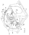
- Table saw 10 which is designated generally by the reference numeral 10 incorporating a switched reluctance motor in accordance with the present invention.
- Table saw 10 comprises a base 12 which supports a generally rectangular work table 14 defining a working surface 16.
- Work table 14 includes a throat plate 18 which includes an elongated slot 23 through which a circular saw blade 22 protrudes.
- Saw blade 22 is capable to being adjusted for angularity with respect to working surface 16 by an angular bevel adjustment mechanism 24 as well as being capable for being adjusted for depth of cut by a height adjustment mechanism 26.
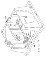
- table saw 10 is illustrated with working surface 16 of work table 14 partially removed and a portion of base 12 cutaway.
- Circular saw blade 22 is rotated by a motor 28 which power saw blade 22 through a gear case 30.
- Bevel adjustment mechanism 24 adjusts the angular position of saw blade 22 by pivoting saw blade 22, motor 28 and gear case 30.
- Height adjustment mechanism 26 adjusts the cutting depth of saw blade 22 by longitudinal movement of saw blade 22, motor 28 and gear case 30.
- the motor 28 has typically been a universal motor that is connected to a belt or gear reduction drive for driving the rotatably mounted saw blade 22.
- the present invention employs a switched reluctance motor as the motor 28 in the table saw 10.
- bevel adjustment mechanism 24 comprises a pair of pivot quadrants 32, a support plate 34, and a locking system 36.
- Each pivot quadrant 32 is attached to a plurality of bosses 38 extending from the bottom of work table 14 using a plurality of bolts 40.
- Each pivot quadrant 32 is designed to pivot around a centre which is located on working surface 16 of work table 14 coincident with the plane of saw blade 22.
- the axis for pivoting support plate 34 lies on working surface 16 and extends through the plane of saw blade 22 when saw blade 22 is generally perpendicular with working surface 16.
- pivot quadrant 32 is comprised of a support bracket 42, a pivot bracket 44 and a retaining strap 46.
- Support bracket 42 is an L-shaped bracket which defines a plurality of holes 48 to facilitate the attachment of pivot quadrant 32 to work table 14 on one leg of the L.
- the opposite leg of the L defines an arcuate slot 50 which controls the pivotal movement of pivot bracket 44 and locates the centre of the pivoting at working surface 16 of work table 14.
- Pivot bracket 44 extends between support bracket 42 and support plate 34 and defines a plurality of holes 52 at one end to facilitate the attachment of support plate 34.
- the opposite end of pivot bracket 44 defines a stamped arcuate protrusion 54 which mates with slot 50 to control the pivoting of pivot bracket 44.
- Protrusion 54 is formed out of the material of pivot bracket 44 and this forming operation defines an arcuate slot 56 once protrusion 54 has been formed.
- Retaining strap 46 extends across pivot bracket 44 and is attached to support bracket 42 to maintain the engagement of protrusion 54 with slot 50.
- Retaining strap 46 defines a formed protrusion 58 which extends into slot 56 to both guide the pivotal movement of pivot bracket 44 and to act as a stop to limit the pivotal movement of pivot bracket 44.
- support plate 34 is a shallow drawn plate which is attached to pivot quadrants 32.
- Support plate 34 is designed to support both height adjustment mechanism 26 and locking system 36.
- Locking system 36 comprises a bearing block 60, a locking rod 62, a locking arm 64, a bearing block cam 66, a locking arm cam 68 and a return spring 70.
- Bearing block 60 is a curved member which is attached to a bracket 72 which is in turn attached to support plate 34. Bearing block 60 thus pivots with support plate 34 and bearing block 60 extends through an arcuate slot 74 in the front face of base 12. While the pivotal movement of support plate 34 moves bearing block 60 within slot 74, it should be understood that the movement of support plate 34 is controlled by pivot quadrants 32 and that a clearance will always exist between bearing block 60 and slot 74.
- Locking rod 62 extends across support plate 34 and through bracket 72 and bearing block 60 in the front of support plate 34 and through a bracket 76 and a bracket 78 located at the rear of support plate 34.
- Bracket 76 is attached to support plate 34 and defines an aperture for accepting and guiding locking rod 62.
- Bracket 78 is attached to work table 14 and it defines an arcuate slot 80 which accepts locking rod 62 and allows for the pivotal movement of support plate 34. While the pivotal movement of support plate 34 moves locking rod 62 within slot 80, it should be understood that the movement of support plate 34 is controlled by pivot quadrants 32 and that a clearance will always exist between locking rod 62 and slot 80.
- locking rod 62 has been inserted through brackets 76 and 78, a washer 82 and a nut 84 are assembled to locking rod 62 to provide adjustment for locking system 34.
- the front end of locking rod 62 extends through bearing block 60 and through a D-shaped embossment 86 which is an integral part of bearing block 60.
- Locking arm 64 is assembled over the end of locking rod 62 and secured to locking rod 62 using a hardened washer 88, a thrust bearing 90, a hardened washer 92 and a nut 94 threadingly received on locking rod 62 as shown in Figure 4.
- Bearing block cam 66 and locking arm cam 68 are disposed between locking arm 64 and bearing block 60.
- D-shaped embossment 86 extends from bearing block 60 through slot 74 in the front face of base 12.
- Bearing block cam 66 includes a D-shaped aperture which mates with embossment 86 and cam 66 is positioned such that the front face of base 12 is sandwiched between bearing block 60 and bearing block cam 66.
- the engagement of the D-shaped aperture of cam 66 with D-shaped embossment 86 prohibits the rotational movement of cam 66 with respect to bearing block 60.
- the face of cam 66 opposite to the front surface of base 12 defines a camming surface 96 which reacts with locking arm cam 68 to activate locking system 34.
- Locking arm 64 defines a D-shaped embossment 98 which mates with a D-shaped aperture extending through locking arm cam 68 such that locking arm cam 68 pivots with locking arm 64 when locking arm 64 pivots on locking rod 62.
- the face of cam 68 opposite to locking arm 64 defines a camming surface 100 which mates with camming surface 96 on cam 66 such that pivoting motion of locking arm 64 with respect to locking rod 62 will cause longitudinal movement of locking rod 62 to activate locking system 36.
- Return spring 70 is disposed on locking rod 62 between an ear 102 formed on locking rod 62 and bearing block 60 in order to urge locking rod 62 towards the rear of base 12 or towards bracket 78.
- Locking rod 62 is shown with an additional ear 102 on the opposite side of return spring 70 to capture spring 70 in the unassembled condition of locking rod 62.
- the additional ear 102 requires that the aperture in bearing block 60 which accepts locking rod 62 be provided with a slot (not shown) to accept the additional ear 102. In this arrangement, the engagement of the additional ear 102 with the slot in bearing block 60 will prohibit any rotational movement of locking rod 62.
- locking system 36 is activated by pivoting locking arm 64 on locking rod 62 which rotates cam 68 with respect to cam 66.
- Camming surface 100 is cammed away from camming surface 96 causing longitudinal movement of locking rod 62.
- the longitudinal movement of locking rod 62 compresses support plate 34 between bracket 78 and the front face of base 12 due to washer 82 and nut 84 engaging bracket 78 and bearing block cam 66 engaging the front surface of base 12.
- the flexibility of locking rod 62 due to a centre off-set area 104 and the flexibility of bracket 78 permit the compression of support plate 34.
- the adjustment for locking system 36 is provided for by nut 84.
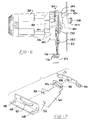
- height adjustment mechanism 26 comprises a pivot link 110, a biasing spring 112, a follower nut 114, a height adjustment screw 116 and a crank handle 118 which function to move saw blade 22, motor 28 and gear case 30 longitudinally with respect to support plate 34.
- Support plate 34 defines a generally rectangular opening 120 within which gear case 30 is located. Located adjacent to and extending generally the entire length of opening 120 are a pair of formed ribs 122 which provide stiffness to support plate 34.
- Gear case 30 includes a housing 124 disposed on one side of support plate 34 and a cover 126 disposed on the opposite side of support plate 34. Cover 126 is secured to housing 124 by a plurality of bolts 128 such that support plate 34 is sandwiched between cover 126 and housing 124.
- Gear case 30 includes a pair of longitudinally extending surfaces 130 which engage the opposing sides of opening 120 to guide the movement of gear case 30 within opening 120.
- Motor 28 is attached to housing 124 and includes an armature shaft 132 having a pinion 134 which meshes with an output gear 136 which is rotatably supported within gear case 30.
- the output gear includes an arbor shaft 138 which provides for the attachment of saw blade 22.
- a prior art solution includes using a double "D" to lock washer 180 or washer 182 to the arbor shaft 138 to prevent dragging, and self-tightening, of the arbor nut 184. This solution requires additional hardware parts or additional machining operations, thus raising manufacturing costs.
- the arbor shaft 138 have a twin lead thread, or double thread.
- the angle of the threads relative to a plane perpendicular to the shaft axis, or alpha angle, in the double thread shaft is larger than the alpha angle in the single thread shaft.
- the larger alpha angle helps reduce the torque applied on the arbor nut 184, diminishing its self-tightening.
- the double thread shaft's alpha angle is twice that of a single thread shaft's alpha angle
- the torque applied on the double-threaded arbor nut would be about half of the torque applied on the single-threaded arbor nut.
- Such reduction of torque minimises the arbor nut's self-tightening.
- this result can also be achieved so long as multiple threads, i.e., triple, quadruple, etc., threads, are used on the arbor shaft.
- the alpha angle should be at least 3° and preferably in a range between 5° and 5.4°. Such range provides a small screw pitch that prevents a thin blade from falling into the space between the threads. Otherwise, the blade would fall into the space between the threads, making the blade eccentric relative to the shaft, causing excess vibration and poor cut characteristics, especially at the normal operating speeds of about 4000 RPM.
- the increased alpha angle solution is also advantageous as it can be implemented with any kind of thread shape.
- the thread cross-sectional shape can be triangular (V-shaped), round (arcuate), trapezoidal, square, etc.
- the thread used in the arbor shaft 138 substantially square and is commonly known as the "ACME thread”.
- cover 126 is provided with a plurality of accurately machines pads 140 which accurately position cover 126 and thus saw blade 22 with respect to support plate 34.
- Machine pads 140 are biased against the datum face on support plate 34 by a plurality of elastomeric springs 142 each of which is disposed within an aperture 144 defined by housing 124.
- a low friction wear pad 146 is disposed between each elastomeric spring 142 and support plate 34 to facilitate the movement of gear case 30 within opening 120.
- cover 126 includes an extension 148 which can be utilised for supporting a splitter and/or guard mechanism for table saw 10 if desired The mounting of the splitter and/or guard mechanism on cover 126 allows the components to travel with saw blade 22 during cutting depth and/or angular adjustments.
- pivot link 110 is pivotably secured to support plate 34 by an appropriate fastener 150.
- One arm of pivot link 110 defines a slot 152 which engages a pin 154 attached to gear case 30.
- the second arm of pivot link 110 defines a slot 156 which engages follower nut 114.
- Biasing spring 112 is a tension spring positioned around fastener 150 and is disposed between pivot link 110 and a retainer 158. Retainer 158 is attached to follower nut 114 and biasing spring 112 is positioned such that its spring force biases gear case 30 towards a downward position.
- Height adjustment screw 116 is rotatably secured at one end by a bracket 160 which is a separate component or bracket 160 can be formed out of support plate 34.
- a nylon bushing 162 is disposed between screw 116 and bracket 160 to facilitate the rotation of screw 116 and provide a smoothness of operation. The loading and thus the wear between screw 116, bushing 162 and bracket 160 is significantly reduced due to the reaction of spring 112 occurring through follower nut 114 and not through screw 116.
- the opposite end of adjustment screw 116 extends through and is rotatably supported by bearing block 60. The portion of adjustment screw 116 which extends beyond bearing block 60 is adapted for securing crank handle 118 to adjustment screw 116 such that rotation of crank handle 118 causes rotation of adjustment screw 116.
- a hardened washer 164 Disposed between bearing block 60 and bracket 72 of support plate 34 is a hardened washer 164, a powdered metal washer 166, a spring thrust washer 168 and a hardened washer 170.
- Powdered metal washer 166 is secured to adjustment screw 116 by press fitting or other means known in the art.
- the biasing of spring thrust washer 168 produces frictional resistance to the rotation of adjustment screw 116 allowing for the accurate positioning of saw blade 22 and the ability of height adjustment mechanism 26 to maintain the position of saw blade 22 during the cutting operation.
- the frictional resistance or drag produced by spring thrust washer 168 maintains the position of adjustment screw 116 and is not affected by the vibration produced by motor 28 and/or the cutting operation.
- the biasing produced by spring thrust washer 168 removes any play which may exist between the various components of height adjustment 26.
- Follower nut 114 is threadingly received on a threaded portion 172 of screw 116 which is located between bracket 160 and bearing block 60.
- follower nut 114 includes a cylindrical finger 174 which extends into retainer 158, into slot 156 of pivot link 110 and into a slot 176 located in support plate 34 to cause the pivoting of pivot link 110 by follower nut 114.
- Slot 176 in support plate 34 prohibits rotation of follower nut 114 and tends to guide follower nut 114 as it moves along screw 116.
- the contact between finger 174 and the edge of slot 176 provides the reaction point for spring 112.
- crank handle 118 when crank handle 118 is rotated, adjustment screw 116 is rotated which causes follower nut 114 to move longitudinally along threaded portion 172 of adjustment screw 116.
- the direction of movement of follower nut 114 will be determined by the design of threaded portion 172 and the direction of rotation of crank handle 118.
- the longitudinal movement of follower nut 114 causes pivotal movement of pivot link 110 due to the engagement of finger 174 which engages slot 156.
- the pivotal movement of pivot link 110 causes the longitudinal movement of gear case 30, motor 28 and saw blade 22 due to the engagement of slot 152 with pin 154.
- the longitudinal movement of gear case 30, motor 28 and saw blade 22 sets the height of saw blade 22 extending through work table 14 and thus the depth of cut.
- cover 126 of gear case 30 supports another unique feature for machine tool 10.
- One of the problems associated with machine tools is the changing of the cutting tool.
- Saw blade 22 is assembled to arbor shaft 138 and is frictionally held in position by a pair of washers 180, 182 and an arbor nut 184.
- Arbor shaft 138 includes a pair of flats 186 which accept a wrench (not shown) in order to stop arbor shaft 138 from rotating when arbor nut 184 is to be loosened or tightened during the changing of saw blade 22.
- the wrench for engaging flats 186 is normally a separate piece which is easily misplaced which then leads to the wedging of a block of wood or other material against saw blade 22 to hold arbor shaft 138.
- the wedging of the block against saw blade 22 is both dangerous and leads to unnecessary loading of the bearings supporting arbor shaft 138.
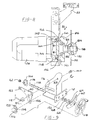
- the present invention includes a lever 188 which is pivotably secured to cover 126.
- a wrench 190 is pivotably secured to lever 188 and moves within a pocket 192 formed by a ridge 194 which is an integral part of cover 126 between an unlocked position shown in Figure 10 and a locked position shown in Figure 11.
- a spring 196 biases wrench 190 into its unlocked position.
- the unlocked position of wrench 190 is shown in Figure 10 where wrench 190 is disconnected from flats 186 and arbor shaft 138 is free to rotate.
- the locked position is shown in Figure 11 where wrench 190 engages flats 186 to prohibit rotation of arbor shaft 138.
- the end of wrench 190 engages ridge 194 at both the front of wrench 190 adjacent arbor shaft 138 to provide support for wrench 190 in the locked position and at the rear of wrench 190 adjacent to lever 188 to provide support to counteract the torque being allied to arbor nut 184.
- Lever 188 is accessible to the operator of table saw 10 through the opening in work table 14 which accepts throat plate 18.
- Lever 188 is designed to extend into the throat plate opening of work table 14 when wrench 190 is in the locked position and saw blade 22 is in its full upward position as shown in Figure 11 to prohibit the assembly of throat plate 18 with work table 14 while wrench 190 is in the locked position. Once wrench 190 is moved to its unlocked position, lever 188 will be removed from the throat plate opening in work table 14 and throat plate 18 can be assembled to work table 14.
- Figure 12 illustrates a bevel angle stop system for bevel adjustment mechanism 24.
- An adjustment cam 200 is attached to the front panel of work table 14 at opposite ends of slot 74.
- a protrusion 202 is formed at both ends of bearing block 60.
- Adjustment cam 200 is tightened in position using a bolt 204 to set the zero degree position of saw blade 22. The tightening of bolt 204 has a tendency to rotate cam 200 in a clockwise direction.
- cam 200 urges cam 200 into contact with protrusion 202 due to the external spiral shape of cam 200 to provide an accurate positioning of the bevel angle for saw blade 22.
- the perpendicularity of saw blade 22 can be set by a square or other means known well in the art.
- the 45o position of saw blade 22 with respect to working surface 16 can be set by a similar adjustment and locking of adjustment cam 200 located on the opposite side of slot 74.
- a schematic control circuit is illustrated showing the switched reluctance motor 28 electrically connected to the electronic motor drive 29 and operated by the switch 300 in the base 12 of the table saw 10.
- Switched reluctance motors rely upon semiconductor switches and complex logic for operation. Such motors are also capable of braking, again relying upon those same semiconductor switches and logic.
- the switch 300 may include first and second contacts.
- the switched reluctance motor 28 upon depression of the switch 300, the switched reluctance motor 28 is energised to drive the rotatably mounted saw blade 22.
- the second contact can be electrically connected to the electronic motor drive 370 to brake the switched reluctance motor 28.
- switched reluctance motors can be controlled to provide braking down to near zero speed, thus reducing total stopping time.
- the electronic motor drive 370 can be configured to sense that the switch 300 is open, in other words, released, and then automatically brake the switched reluctance motor 28.
- the electronic motor drive 370 can be configured in any desired manner to work in conjunction with the switch 30 to brake the switched reluctance motor 28.
- variable speed control to the switched reluctance motor 28.
- Another variation can include a soft start, i.e., relatively slow ramp up of motor speed, in the electronic motor drive 370 in order to reduce the strain on a gear reduction drive as well as reduce the starting in rush current to the switched reluctance motor 28. This is an advantage when long extension cords are used.
- the table saw with switched reluctance motor eliminates wear and tear on brushes and commutators as in prior art universal motors as well as regenerative or dynamic braking associated with the universal motor. Wear and tear is substantially eliminated because switched reluctance motors rely upon semiconductor switches and complex logic to operate. Because switched reluctance motors are capable of braking, as a result of the semiconductor switches and logic, they can be controlled to provide braking down to near zero speed, thus reducing the total stopping time.
Landscapes
- Engineering & Computer Science (AREA)
- Mechanical Engineering (AREA)
- Sawing (AREA)
Applications Claiming Priority (4)
| Application Number | Priority Date | Filing Date | Title |
|---|---|---|---|
| US4445997P | 1997-04-29 | 1997-04-29 | |
| US44459P | 1997-04-29 | ||
| US5852197P | 1997-09-11 | 1997-09-11 | |
| US58521P | 1997-09-11 |
Publications (3)
| Publication Number | Publication Date |
|---|---|
| EP0875324A2 true EP0875324A2 (fr) | 1998-11-04 |
| EP0875324A3 EP0875324A3 (fr) | 2002-06-19 |
| EP0875324B1 EP0875324B1 (fr) | 2006-09-27 |
Family
ID=26721585
Family Applications (1)
| Application Number | Title | Priority Date | Filing Date |
|---|---|---|---|
| EP19980303126 Expired - Lifetime EP0875324B1 (fr) | 1997-04-29 | 1998-04-23 | Scie à table |
Country Status (2)
| Country | Link |
|---|---|
| EP (1) | EP0875324B1 (fr) |
| DE (1) | DE69835973T2 (fr) |
Cited By (3)
| Publication number | Priority date | Publication date | Assignee | Title |
|---|---|---|---|---|
| CN101733472B (zh) * | 2008-11-18 | 2013-04-03 | 苏州宝时得电动工具有限公司 | 一种台式工具 |
| EP3268184A4 (fr) * | 2015-03-12 | 2019-03-20 | Robert Bosch GmbH | Moteur d'outil électrique a bruit électrique réduit |
| CN110076914A (zh) * | 2019-04-29 | 2019-08-02 | 锐奇控股股份有限公司 | 可调节底板装置及包含其的云石机 |
Family Cites Families (16)
| Publication number | Priority date | Publication date | Assignee | Title |
|---|---|---|---|---|
| US74749A (en) * | 1868-02-25 | Ela galley | ||
| US2313617A (en) * | 1941-06-26 | 1943-03-09 | O M Mitchell | Saw bench |
| US2788812A (en) * | 1955-05-24 | 1957-04-16 | John W Jacobs | Adjustable multi-blade dado cutter |
| US2852047A (en) * | 1956-04-16 | 1958-09-16 | Duro Metal Products Co | Tilting and elevating mechanism for a disc type table saw |
| US3177977A (en) * | 1962-06-26 | 1965-04-13 | Rockwell Mfg Co | Brake for radial arm saws or like machine tools |
| SE385806B (sv) * | 1973-07-09 | 1976-07-26 | Partner Ab | Portabelt kapredskap |
| DE2646515A1 (de) * | 1976-10-15 | 1978-04-20 | Leopold Jaegers | Fuehrung fuer ein saegeblatt |
| US4549455A (en) * | 1981-12-02 | 1985-10-29 | Perilloux Jr Milton | Combination table saw |
| US4516612A (en) * | 1982-09-03 | 1985-05-14 | Wiley Edward R | Multipurpose table saw |
| IT8223584U1 (it) * | 1982-11-30 | 1984-05-30 | Black & Decker Inc | Macchina utensile portatile con unità operatrice montata su una colonna abbattibile e posizionabile lateralmente al piano di lavoro |
| US4657428A (en) * | 1985-09-10 | 1987-04-14 | Wiley Edward R | Quick change mechanism for circular saw blades and other spinning disc devices |
| DE8605687U1 (de) * | 1986-03-01 | 1986-06-12 | Josef Scheppach Maschinenfabrik Gmbh & Co, 8873 Ichenhausen | Holzbearbeitungsmaschine |
| CA2145210A1 (fr) * | 1994-10-31 | 1996-05-01 | David E. Beth | Scie a onglets a position variable equipee d'un moteur a reluctance |
| GB9425391D0 (en) * | 1994-12-12 | 1995-02-15 | Black & Decker Inc | Bevel table saw adjustment |
| US5875698A (en) * | 1996-06-17 | 1999-03-02 | Black & Decker Inc. | Blade and motor carrier with height/angle adjustment mechanism |
| US5857507A (en) * | 1996-09-20 | 1999-01-12 | Black & Decker Inc. | Table saw |
-
1998
- 1998-04-23 DE DE69835973T patent/DE69835973T2/de not_active Expired - Lifetime
- 1998-04-23 EP EP19980303126 patent/EP0875324B1/fr not_active Expired - Lifetime
Cited By (5)
| Publication number | Priority date | Publication date | Assignee | Title |
|---|---|---|---|---|
| CN101733472B (zh) * | 2008-11-18 | 2013-04-03 | 苏州宝时得电动工具有限公司 | 一种台式工具 |
| EP3268184A4 (fr) * | 2015-03-12 | 2019-03-20 | Robert Bosch GmbH | Moteur d'outil électrique a bruit électrique réduit |
| US10493543B2 (en) | 2015-03-12 | 2019-12-03 | Robert Bosch Tool Corporation | Power tool motor with reduced electrical noise |
| CN110076914A (zh) * | 2019-04-29 | 2019-08-02 | 锐奇控股股份有限公司 | 可调节底板装置及包含其的云石机 |
| CN110076914B (zh) * | 2019-04-29 | 2024-02-09 | 锐奇控股股份有限公司 | 可调节底板装置及包含其的云石机 |
Also Published As
| Publication number | Publication date |
|---|---|
| DE69835973T2 (de) | 2007-08-30 |
| EP0875324A3 (fr) | 2002-06-19 |
| DE69835973D1 (de) | 2006-11-09 |
| EP0875324B1 (fr) | 2006-09-27 |
Similar Documents
| Publication | Publication Date | Title |
|---|---|---|
| US20010032534A1 (en) | Table saw with switched reluctance motor | |
| EP1616677B1 (fr) | Lame de coupe et support moteur à mécanisme de réglage de hauteur et angle | |
| EP0860250B1 (fr) | Dispositif de serrage du palier pivotable pour scie à onglets | |
| US5957021A (en) | Guard and control apparatuses for sliding compound miter saw | |
| US6035754A (en) | Bevel locking system for a sliding compound miter saw | |
| US6971297B1 (en) | Guard and control apparatuses for sliding compound miter saw | |
| US6631661B2 (en) | Bevel locking system for a sliding compound miter saw | |
| EP1211032B1 (fr) | Capot de protection et appareils de commande pour une scie à onglet du type combiné | |
| EP0875324B1 (fr) | Scie à table | |
| JPS6234725Y2 (fr) | ||
| JPH0535204U (ja) | 電気丸のこの切込み量調整機構 |
Legal Events
| Date | Code | Title | Description |
|---|---|---|---|
| PUAI | Public reference made under article 153(3) epc to a published international application that has entered the european phase |
Free format text: ORIGINAL CODE: 0009012 |
|
| AK | Designated contracting states |
Kind code of ref document: A2 Designated state(s): AT BE CH CY DE DK ES FI FR GB GR IE IT LI LU MC NL PT SE |
|
| AX | Request for extension of the european patent |
Free format text: AL;LT;LV;MK;RO;SI |
|
| 17P | Request for examination filed |
Effective date: 19990206 |
|
| PUAL | Search report despatched |
Free format text: ORIGINAL CODE: 0009013 |
|
| RIC1 | Information provided on ipc code assigned before grant |
Free format text: 7B 23D 45/06 A, 7B 27B 5/24 B, 7B 27B 5/29 B, 7B 27B 5/32 B |
|
| AK | Designated contracting states |
Kind code of ref document: A3 Designated state(s): AT BE CH CY DE DK ES FI FR GB GR IE IT LI LU MC NL PT SE |
|
| AX | Request for extension of the european patent |
Free format text: AL;LT;LV;MK;RO;SI |
|
| 17Q | First examination report despatched |
Effective date: 20021014 |
|
| AKX | Designation fees paid |
Designated state(s): DE GB IT |
|
| GRAP | Despatch of communication of intention to grant a patent |
Free format text: ORIGINAL CODE: EPIDOSNIGR1 |
|
| RTI1 | Title (correction) |
Free format text: TABLE SAW |
|
| GRAS | Grant fee paid |
Free format text: ORIGINAL CODE: EPIDOSNIGR3 |
|
| GRAA | (expected) grant |
Free format text: ORIGINAL CODE: 0009210 |
|
| AK | Designated contracting states |
Kind code of ref document: B1 Designated state(s): DE GB IT |
|
| PG25 | Lapsed in a contracting state [announced via postgrant information from national office to epo] |
Ref country code: IT Free format text: LAPSE BECAUSE OF FAILURE TO SUBMIT A TRANSLATION OF THE DESCRIPTION OR TO PAY THE FEE WITHIN THE PRESCRIBED TIME-LIMIT;WARNING: LAPSES OF ITALIAN PATENTS WITH EFFECTIVE DATE BEFORE 2007 MAY HAVE OCCURRED AT ANY TIME BEFORE 2007. THE CORRECT EFFECTIVE DATE MAY BE DIFFERENT FROM THE ONE RECORDED. Effective date: 20060927 |
|
| REG | Reference to a national code |
Ref country code: GB Ref legal event code: FG4D |
|
| REF | Corresponds to: |
Ref document number: 69835973 Country of ref document: DE Date of ref document: 20061109 Kind code of ref document: P |
|
| PLBE | No opposition filed within time limit |
Free format text: ORIGINAL CODE: 0009261 |
|
| STAA | Information on the status of an ep patent application or granted ep patent |
Free format text: STATUS: NO OPPOSITION FILED WITHIN TIME LIMIT |
|
| 26N | No opposition filed |
Effective date: 20070628 |
|
| PGFP | Annual fee paid to national office [announced via postgrant information from national office to epo] |
Ref country code: GB Payment date: 20120425 Year of fee payment: 15 |
|
| PGFP | Annual fee paid to national office [announced via postgrant information from national office to epo] |
Ref country code: IT Payment date: 20120424 Year of fee payment: 15 |
|
| PGFP | Annual fee paid to national office [announced via postgrant information from national office to epo] |
Ref country code: DE Payment date: 20130429 Year of fee payment: 16 |
|
| GBPC | Gb: european patent ceased through non-payment of renewal fee |
Effective date: 20130423 |
|
| PG25 | Lapsed in a contracting state [announced via postgrant information from national office to epo] |
Ref country code: GB Free format text: LAPSE BECAUSE OF NON-PAYMENT OF DUE FEES Effective date: 20130423 |
|
| PG25 | Lapsed in a contracting state [announced via postgrant information from national office to epo] |
Ref country code: IT Free format text: LAPSE BECAUSE OF NON-PAYMENT OF DUE FEES Effective date: 20130423 |
|
| REG | Reference to a national code |
Ref country code: DE Ref legal event code: R119 Ref document number: 69835973 Country of ref document: DE |
|
| REG | Reference to a national code |
Ref country code: DE Ref legal event code: R119 Ref document number: 69835973 Country of ref document: DE Effective date: 20141101 |
|
| PG25 | Lapsed in a contracting state [announced via postgrant information from national office to epo] |
Ref country code: DE Free format text: LAPSE BECAUSE OF NON-PAYMENT OF DUE FEES Effective date: 20141101 |