EP0875332A2 - Method of machining for a cutting die, photo-eched from a carrier base, and cylindrical cutting die manufactured by this method - Google Patents
Method of machining for a cutting die, photo-eched from a carrier base, and cylindrical cutting die manufactured by this method Download PDFInfo
- Publication number
- EP0875332A2 EP0875332A2 EP98110376A EP98110376A EP0875332A2 EP 0875332 A2 EP0875332 A2 EP 0875332A2 EP 98110376 A EP98110376 A EP 98110376A EP 98110376 A EP98110376 A EP 98110376A EP 0875332 A2 EP0875332 A2 EP 0875332A2
- Authority
- EP
- European Patent Office
- Prior art keywords
- webs
- punch
- roller
- punch webs
- label material
- Prior art date
- Legal status (The legal status is an assumption and is not a legal conclusion. Google has not performed a legal analysis and makes no representation as to the accuracy of the status listed.)
- Withdrawn
Links
Images



Classifications
-
- B—PERFORMING OPERATIONS; TRANSPORTING
- B31—MAKING ARTICLES OF PAPER, CARDBOARD OR MATERIAL WORKED IN A MANNER ANALOGOUS TO PAPER; WORKING PAPER, CARDBOARD OR MATERIAL WORKED IN A MANNER ANALOGOUS TO PAPER
- B31D—MAKING ARTICLES OF PAPER, CARDBOARD OR MATERIAL WORKED IN A MANNER ANALOGOUS TO PAPER, NOT PROVIDED FOR IN SUBCLASSES B31B OR B31C
- B31D1/00—Multiple-step processes for making flat articles ; Making flat articles
- B31D1/02—Multiple-step processes for making flat articles ; Making flat articles the articles being labels or tags
- B31D1/021—Making adhesive labels having a multilayered structure, e.g. provided on carrier webs
-
- B—PERFORMING OPERATIONS; TRANSPORTING
- B23—MACHINE TOOLS; METAL-WORKING NOT OTHERWISE PROVIDED FOR
- B23P—METAL-WORKING NOT OTHERWISE PROVIDED FOR; COMBINED OPERATIONS; UNIVERSAL MACHINE TOOLS
- B23P15/00—Making specific metal objects by operations not covered by a single other subclass or a group in this subclass
- B23P15/28—Making specific metal objects by operations not covered by a single other subclass or a group in this subclass cutting tools
- B23P15/40—Making specific metal objects by operations not covered by a single other subclass or a group in this subclass cutting tools shearing tools
- B23P15/406—Making specific metal objects by operations not covered by a single other subclass or a group in this subclass cutting tools shearing tools rotary or plane die cutters
-
- B—PERFORMING OPERATIONS; TRANSPORTING
- B26—HAND CUTTING TOOLS; CUTTING; SEVERING
- B26F—PERFORATING; PUNCHING; CUTTING-OUT; STAMPING-OUT; SEVERING BY MEANS OTHER THAN CUTTING
- B26F1/00—Perforating; Punching; Cutting-out; Stamping-out; Apparatus therefor
- B26F1/38—Cutting-out; Stamping-out
- B26F1/44—Cutters therefor; Dies therefor
-
- B—PERFORMING OPERATIONS; TRANSPORTING
- B31—MAKING ARTICLES OF PAPER, CARDBOARD OR MATERIAL WORKED IN A MANNER ANALOGOUS TO PAPER; WORKING PAPER, CARDBOARD OR MATERIAL WORKED IN A MANNER ANALOGOUS TO PAPER
- B31D—MAKING ARTICLES OF PAPER, CARDBOARD OR MATERIAL WORKED IN A MANNER ANALOGOUS TO PAPER, NOT PROVIDED FOR IN SUBCLASSES B31B OR B31C
- B31D1/00—Multiple-step processes for making flat articles ; Making flat articles
- B31D1/02—Multiple-step processes for making flat articles ; Making flat articles the articles being labels or tags
- B31D1/026—Cutting or perforating
-
- B—PERFORMING OPERATIONS; TRANSPORTING
- B26—HAND CUTTING TOOLS; CUTTING; SEVERING
- B26F—PERFORATING; PUNCHING; CUTTING-OUT; STAMPING-OUT; SEVERING BY MEANS OTHER THAN CUTTING
- B26F1/00—Perforating; Punching; Cutting-out; Stamping-out; Apparatus therefor
- B26F1/38—Cutting-out; Stamping-out
- B26F1/384—Cutting-out; Stamping-out using rotating drums
-
- B—PERFORMING OPERATIONS; TRANSPORTING
- B26—HAND CUTTING TOOLS; CUTTING; SEVERING
- B26F—PERFORATING; PUNCHING; CUTTING-OUT; STAMPING-OUT; SEVERING BY MEANS OTHER THAN CUTTING
- B26F1/00—Perforating; Punching; Cutting-out; Stamping-out; Apparatus therefor
- B26F1/38—Cutting-out; Stamping-out
- B26F1/44—Cutters therefor; Dies therefor
- B26F2001/4472—Cutting edge section features
-
- B—PERFORMING OPERATIONS; TRANSPORTING
- B26—HAND CUTTING TOOLS; CUTTING; SEVERING
- B26F—PERFORATING; PUNCHING; CUTTING-OUT; STAMPING-OUT; SEVERING BY MEANS OTHER THAN CUTTING
- B26F1/00—Perforating; Punching; Cutting-out; Stamping-out; Apparatus therefor
- B26F1/38—Cutting-out; Stamping-out
- B26F1/44—Cutters therefor; Dies therefor
- B26F2001/4481—Cutters therefor; Dies therefor having special lateral or edge outlines or special surface shapes, e.g. apertures
-
- Y—GENERAL TAGGING OF NEW TECHNOLOGICAL DEVELOPMENTS; GENERAL TAGGING OF CROSS-SECTIONAL TECHNOLOGIES SPANNING OVER SEVERAL SECTIONS OF THE IPC; TECHNICAL SUBJECTS COVERED BY FORMER USPC CROSS-REFERENCE ART COLLECTIONS [XRACs] AND DIGESTS
- Y10—TECHNICAL SUBJECTS COVERED BY FORMER USPC
- Y10T—TECHNICAL SUBJECTS COVERED BY FORMER US CLASSIFICATION
- Y10T29/00—Metal working
- Y10T29/49—Method of mechanical manufacture
- Y10T29/49995—Shaping one-piece blank by removing material
-
- Y—GENERAL TAGGING OF NEW TECHNOLOGICAL DEVELOPMENTS; GENERAL TAGGING OF CROSS-SECTIONAL TECHNOLOGIES SPANNING OVER SEVERAL SECTIONS OF THE IPC; TECHNICAL SUBJECTS COVERED BY FORMER USPC CROSS-REFERENCE ART COLLECTIONS [XRACs] AND DIGESTS
- Y10—TECHNICAL SUBJECTS COVERED BY FORMER USPC
- Y10T—TECHNICAL SUBJECTS COVERED BY FORMER US CLASSIFICATION
- Y10T83/00—Cutting
- Y10T83/929—Tool or tool with support
- Y10T83/9372—Rotatable type
Definitions
- the invention relates to a method for processing from photochemically etched out of a substrate Diecuts, by means of which labels are made on a backing tape releasably adhering label material by rolling the punch webs over the label material to be punched.
- the support base can be the body of a roller be, but also a sleeve-shaped on a roller attached sheet metal.
- EP-A-0 321 590 describes a method for making a punch with sharp Cutting edges for label cutters concerns.
- a punch body there in a first Process step provided with a burr by etching, which is then carried out in a second process step Hammering and / or scraping into a sharp Cutting edge is converted, the punch body is placed on a horizontal worktop.
- the object of the invention is a method Specify the type mentioned at the beginning, to punch webs long service life with precise punching properties leads.
- the procedure is to solve this problem characterized in that the punch webs by Milling by means of a truncated cone, the long sides the punch stays attacking around its axis rotating cutter with a triangular cross section flute-shaped sides is given.
- the method is preferably characterized in that that the milled punch bars with a Tool can be reworked by hand.
- the carrier pad is one Roller or a sleeve-like to be attached to a roller Sheet.
- the Roll has a central portion on which the Punch webs, and on both sides at a distance from the Midsection has support sections, the Radius around the thickness of the backing tape - preferably by 0.08 to 0.25 mm - larger than the radius of the Middle section including the punch webs.
- the service life of the roller or sheet and the punching precision is increased by the fact that the roller is turned from a steel blank roller, which before the Turn at least superficially to about 35 to 45 HRC has been cured, or that the roll is made from a steel blank roll is rotated, which after rotating at least superficially hardened to about 35 to 65 HRC or that the sheet is made of a steel that at least superficially hardened to 45 to 55 HRC is.
- the width of the feet of the punch webs is preferred 0.5 to 1.0 mm.
- the height of the punch webs is preferably somewhat larger than the thickness of the label stock and is preferably 0.4 to 1.0 mm.
- the width of the upper boundary surfaces of the etched out photochemically - not yet through Machined milling - punch webs is 0.1 to 0.8 mm.
- a particularly long service life of the punch webs is obtained if the process is characterized by it is that the height of the in the rolling direction (direction L) running punch webs - at most, except for end sections this punch webs - preferably by 0.007 to 0.011 mm - is lower than the height of the cross to Punching webs (direction Q) running - again, at most, except for end sections of this Punch bars.
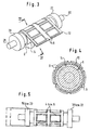
- Fig. 1 shows a first embodiment of a Punching roller in the finished state.
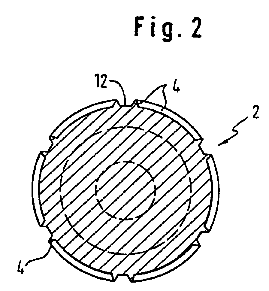
- Fig. 2 shows a section along II-II in fig. 1.
- Fig. 3 shows a second embodiment of a Roll one when folding and sleeve-shaped bending the sheet metal provided on the punch webs.
- Fig. 4 shows a section along IV-IV in fig. 3rd
- Fig. 5 shows a side view of a finished Punching roller according to fig. 1 or fig. 3rd
- the fig. 6a to 6d explain different ones Processing steps of the punch webs.
- Fig. 7 shows a rectangularly closed punch web (In principle, the punch bars do not need to be closed).
- FIG. 8 shows a milling machine for milling photochemically from a cylinder body or from an um etched a cylinder body bent sheet metal Punch bars.
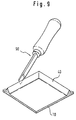
- Fig. 9 shows schematically a manual processing of the Punch bars.
- the fig. 1 and 2 show a roller 2, from the Body punch lands 4 photochemically etched out and are then machined by milling.
- Figures 3 and 4 show a roller 6 to the one with photochemically etched out and then milled punch webs 8 provided sheet 10 sleeve-shaped is bent around.
- the punch webs 4 on a central section 12 or 14 the roller 2 or 6, on both sides at a distance Support sections 16, 18 and 20, 22 are provided, whose radius is about the thickness of the underlay Label material - preferably 0.8 to 0.25 mm - larger than the radius of the central section 12 or 14 including the punch webs 4 and 8 respectively.
- the former Radius in Fig. 5 is D, the latter Radius in fig. 5 labeled d.
- To the support sections 16, 18 and 20, 22 close trunnions 24, 26 or 28, 30.
- the rollers 2 and 6 are off an originally cylindrical steel blank roller, which at least superficially hardened to about 60 HRC was turned.
- FIG. 6a shows a punch web 40 as it passes through Photochemical etching arises.
- the width of his foot 42 is 0.5 to 1.0 mm, the width of its upper Boundary surface 44 0.1 to 0.8 mm, its height 46 (Etching depth) about 0.4 to 1.0 mm.
- Its side faces 48, 50 are, as is inevitable with photo etching, in the shape of a groove because the upper boundary surface is used for photoetching through an etch-resistant material (photoresist) is covered.
- the punch web 40 is given a triangular shape Cross section with 42 in the area of his foot remaining fillet-shaped sections 54, 56 of the flute-shaped side surfaces 48, 50.
- the height 58 of the milled punch web 40 depends on how far the cutter 52 towards the center line 60 of the Stamping webs 40 is moved. This movement is in the program the machine tool used. 6d shows a milled punch web 40.
- Fig. 7 shows closed to a rectangle Stamping webs 62, 64, 66, 68. Die in the rolling direction (direction of rotation) the rollers 2 and 6 extending punch webs 62, 66 are over most of their length (except for their end portions 70) preferably by 0.007 to 0.011 mm lower than the height of the cross to the direction of rolling running punch webs 64, 68. The difference in height is marked with ⁇ . Such differences in height are also by programming the to achieve each machine tool used.
- Fig. 8 shows a side view of a machine tool 84, in which a roller 2, optionally with a she bent sheet metal, between a work spindle 86 and a tailstock 88 is clamped.
- the work spindle 86 is programmed when milling. Of the Milling cutter 52 is up and down, to the left and right, in front and back programmed to move (coordinate direction x, y and z).
- Fig. 9 shows a scraper 90 with which a milled Punching post is reworked by hand.
Landscapes
- Engineering & Computer Science (AREA)
- Mechanical Engineering (AREA)
- Life Sciences & Earth Sciences (AREA)
- Forests & Forestry (AREA)
- Perforating, Stamping-Out Or Severing By Means Other Than Cutting (AREA)
- Making Paper Articles (AREA)
- Polishing Bodies And Polishing Tools (AREA)
- Printing Plates And Materials Therefor (AREA)
- Mechanical Treatment Of Semiconductor (AREA)
Abstract
Die Erfindung betrifft ein Verfahren zum Bearbeiten von
aus einer Trägerunterlage (2) fotochemisch herausgeätzten
Stanzstegen (4), mittels denen Etiketten aus auf
einem Unterlagsband lösbar haftendem Etikettenmaterial
durch Wälzen der Stanzstege (4) über das Etikettenmaterial
zu stanzen sind, wobei den Stanzstegen (4) durch
Fräsen mittels eines kegelstumpfförmigen, die Längsseiten
der Stanzstege (4) angreifenden, um seine Achse
rotierenden Fräsers ein dreieckförmiger Querschnitt mit
hohlkehlenförmigen Seiten gegeben wird, und die Trägerunterlage
(2) eine Walze (2) oder ein währen des
Fräsens auf einer Walze hülsenförmig befestigte Blech
ist.
Description
Die Erfindung betrifft ein Verfahren zum Bearbeiten von aus einer Trägerunterlage fotochemisch herausgeätzten Stanzstegen, mittels denen Etiketten aus auf einem Unterlagsband lösbar haftendem Etikettenmaterial durch Wälzen der Stanzstege über das Etikettenmaterial zu stanzen sind.The invention relates to a method for processing from photochemically etched out of a substrate Diecuts, by means of which labels are made on a backing tape releasably adhering label material by rolling the punch webs over the label material to be punched.
Die Trägerunterlage kann der Körper einer Walze sein, aber auch ein hülsenförmig auf einer Walze befestigtes Blech.The support base can be the body of a roller be, but also a sleeve-shaped on a roller attached sheet metal.
Es hat sich erweisen, daß nur fotochemisch herausgeätzten Stanzstege, da sie notwendigerweise verhältnismäßig breite obere Begrenzungsflächen haben, nicht ohne weiters zum Herausstanzen von Etiketten geeignet sind.It has been shown that only photochemically etched out Punchers as they are necessarily proportionate have wide upper boundary surfaces, not without further ado for punching out labels are suitable.
Ein Verfahren der in der Einleitung erwähnten Art ist aus der EP-A-0 321 590 bekannt, die ein Verfahren zum Herstellen eines Stanzwerkzeugs mit scharfen Schneidkanten für Etikettenschneidgeräte betrifft. Um zu erreichen daß die Schneidkanten eine konstante Höhe aufweisen, wird ein Stanzkörper dort in einem ersten Verfahrensschritt durch Ätzen mit einem Grat versehen, der dann in einem zweiten Verfahrensschritt durch Hämmern und/oder spanabhebendes Schaben in eine scharfe Schneidkante umgewandelt wird, wobei der Stanzkörper auf einer horizontalen Arbeitsplatte aufgelegt ist.A procedure of the kind mentioned in the introduction is known from EP-A-0 321 590 which describes a method for making a punch with sharp Cutting edges for label cutters concerns. Around to achieve that the cutting edges have a constant height have a punch body there in a first Process step provided with a burr by etching, which is then carried out in a second process step Hammering and / or scraping into a sharp Cutting edge is converted, the punch body is placed on a horizontal worktop.
Aufgabe der Erfindung ist es, ein Verfahren eingangs genannter Art anzugeben, das zu Stanzstegen hoher Lebensdauer mit präzisen Stanzeigenschaften führt.The object of the invention is a method Specify the type mentioned at the beginning, to punch webs long service life with precise punching properties leads.
Zur Lösung dieser Aufgabe ist das Verfahren dadurch gekennzeichnet, daß den Stanzstegen durch Fräsen mittels eines kegelstumpfförmigen, die Längsseiten der Stanzstege angreifenden, um seine Achse rotierenden Fräsers ein dreieckförmiger Querschnitt mit hohlkehlenförmigen Seiten gegeben wird. The procedure is to solve this problem characterized in that the punch webs by Milling by means of a truncated cone, the long sides the punch stays attacking around its axis rotating cutter with a triangular cross section flute-shaped sides is given.
Um eine weitere Präzisierung der Stanzstege zu erhalten, ist das Verfahren bevorzugt dadurch gekennzeichnet, daß die gefrästen Stanzstege mit einem Werkzeug von Hand nachgearbeitet werden.To further clarify the punch bars received, the method is preferably characterized in that that the milled punch bars with a Tool can be reworked by hand.
Wie schon angeführt, ist die Trägerunterlage einer Walze oder ein auf einer Walze hülsenförmig zu befestigendes Blech.As already mentioned, the carrier pad is one Roller or a sleeve-like to be attached to a roller Sheet.
Um die Stanzstege beim Stanzen in einem vorgegebenen Abstand von einer Stanzunterlage zu halten, so daß die Stanzstege möglichst nur das Etikettenmaterial durchstanzen, nicht aber deren Unterlagsband, ist das Verfahren bevorzugt dadurch gekennzeichnet, daß die Walze einen Mittelabschnitt aufweist, auf dem sich die Stanzstege befinden, und beidseitig in Abstand von dem Mittelabschnitt Abstützabschnitte aufweist, deren Radius um etwa die Dicke des Unterlagsbands - vorzugsweise um 0,08 bis 0,25 mm - größer als der Radius des Mittelabschnitts einschließlich der Stanzstege ist.To the punch bars when punching in a predetermined Keep a distance from a cutting pad so that the punch bars, if possible, only the label material punching through, but not their underlay, that's it Process preferably characterized in that the Roll has a central portion on which the Punch webs, and on both sides at a distance from the Midsection has support sections, the Radius around the thickness of the backing tape - preferably by 0.08 to 0.25 mm - larger than the radius of the Middle section including the punch webs.
Die Lebensdauer der Walze bzw. des Blechs und deren Stanzpräzision wird dadurch erhöht, daß die Walze aus einer Stahl-Rohlingswalze gedreht wird, die vor dem Drehen wenigstens oberflächlig auf etwa 35 bis 45 HRC gehärtet wurde, oder daß die Walze aus einer Stahl-Rohlingswalze gedreht wird, die nach dem Drehen wenigstens oberflächlich auf etwa 35 bis 65 HRC gehärtet wird, oder daß das Blech aus einem Stahl besteht, der wenigstens oberflächlich auf 45 bis 55 HRC gehärtet ist.The service life of the roller or sheet and the punching precision is increased by the fact that the roller is turned from a steel blank roller, which before the Turn at least superficially to about 35 to 45 HRC has been cured, or that the roll is made from a steel blank roll is rotated, which after rotating at least superficially hardened to about 35 to 65 HRC or that the sheet is made of a steel that at least superficially hardened to 45 to 55 HRC is.
Folgende Bemessungsangaben haben sich als besonders vorteilhaft erwiesen:The following design information has proven to be special proven to be advantageous:
Die Breite der Füße der Stanzstege beträgt bevorzugt 0,5 bis 1,0 mm.The width of the feet of the punch webs is preferred 0.5 to 1.0 mm.
Die Höhe der Stanzstege ist bevorzugt etwas größer als die Dicke des Etikettenmaterials und beträgt bevorzugt 0,4 bis 1,0 mm. The height of the punch webs is preferably somewhat larger than the thickness of the label stock and is preferably 0.4 to 1.0 mm.
Die Breite der oberen Begrenzungsflächen der fotochemisch herausgeätzten - also noch nicht durch Fräsen bearbeiteten - Stanzstege beträgt 0,1 bis 0,8 mm.The width of the upper boundary surfaces of the etched out photochemically - not yet through Machined milling - punch webs is 0.1 to 0.8 mm.
Eine besonders hohe Lebensdauer der Stanzstege erhält man, wenn das Verfahren dadurch gekennzeichnet ist, daß die Höhe der in Wälzrichtung (Richtung L) verlaufenden Stanzstege - allenfalls bis auf Endabscnitte dieser Stanzstege - vorzugsweise um 0,007 bis 0,011 mm - niedriger ist, als die Höhe der quer zur Wälzrichtung (Richtung Q) verlaufenden Stanzstege - wiederum allenfalls bis auf Endabschnitte dieser Stanzstege.A particularly long service life of the punch webs is obtained if the process is characterized by it is that the height of the in the rolling direction (direction L) running punch webs - at most, except for end sections this punch webs - preferably by 0.007 to 0.011 mm - is lower than the height of the cross to Punching webs (direction Q) running - again, at most, except for end sections of this Punch bars.
Im folgenden wird die Erfindung an Ausführungsbeispielen unter Hinweis auf die beigefügten Zeichnungen beschrieben.In the following the invention is based on exemplary embodiments with reference to the attached drawings described.
Fig. 1 zeigt eine erste Ausführungsform einer Stanzwalze im Fertigzustand.Fig. 1 shows a first embodiment of a Punching roller in the finished state.
Fig. 2 zeigt einen Schnitt längs II-II in fig. 1.Fig. 2 shows a section along II-II in fig. 1.
Fig. 3 zeigt eine zweite Ausführungsform einer Walze beim Umlegen und hülsenförmigen Biegen eines mit den Stanzstegen versehenen Blechs.Fig. 3 shows a second embodiment of a Roll one when folding and sleeve-shaped bending the sheet metal provided on the punch webs.
Fig. 4 zeigt einen Schnitt längs IV-IV in fig. 3.Fig. 4 shows a section along IV-IV in fig. 3rd
Fig. 5 zeigt eine Seitenansicht einer fertigen Stanzwalze nach fig. 1 oder fig. 3.Fig. 5 shows a side view of a finished Punching roller according to fig. 1 or fig. 3rd
Die fig. 6a bis 6d erläutern unterschiedliche Bearbeitungsschritte der Stanzstege.The fig. 6a to 6d explain different ones Processing steps of the punch webs.
Fig. 7 zeigt einen rechteckig geschlossenen Stanzsteg (grundsätzlich brauchen die Stanzstege nicht geschlossen zu sein).Fig. 7 shows a rectangularly closed punch web (In principle, the punch bars do not need to be closed).
Fig. 8 zeigt eine Fräsmaschine zum Fräsen von fotochemisch aus einem Zylinderkörper oder aus einem um einen Zylinderkörper gebogenen Blech herausgeätzten Stanzstegen.8 shows a milling machine for milling photochemically from a cylinder body or from an um etched a cylinder body bent sheet metal Punch bars.
Fig. 9 zeigt schematisch eine Handbearbeitung der Stanzstege.Fig. 9 shows schematically a manual processing of the Punch bars.
Die fig. 1 und 2 zeigen eine Walze 2, aus deren
Körper Stanzstege 4 fotochemisch herausgeätzt und
anschließend durch Fräsen bearbeitet sind.The fig. 1 and 2 show a
Die figuren 3 und 4 zeigen eine Walze 6, um das
ein mit fotochemisch herausgeätzten und anschließend
gefrästen Stanzstegen 8 versehenes Blech 10 hülsenförmig
herumgebogen ist. In beiden Fällen befinden sich
die Stanzstege 4, auf einem Mittelabschnitt 12 bzw. 14
der Walze 2 bzw. 6, beidseitig von dem in Abstand
Abstützabscnitte 16, 18 bzw. 20, 22 vorgesehen sind,
deren Radius um etwa die Dicke des Unterlagsbands der
Etikettenmaterials - vorzugsweise 0,8 bis 0,25 mm -
größer als der Radius des Mittelabschnitts 12 bzw. 14
einschließlich der Stanzstege 4 bzw. 8 ist. Der erstgenannte
Radius ist in Fig. 5 mit D, der letztgenannte
Radius in fig. 5 mit d bezeichnet. An die Abstützabschnitte
16, 18 bzw. 20, 22 schließen sich Lagerzapfen
24, 26 bzw. 28, 30 an. Die Walzen 2 bzw. 6 sind aus
einer ursprünglich zylindrischen Stahl-Rohlingswalze,
die wenigstens oberflächlich auf etwa 60 HRC gehärtet
wurde, gedreht.Figures 3 and 4 show a
Fig. 6a zeigt einen Stanzsteg 40, wie er durch
fotochemisches Ätzen entsteht. Die Breite seines Fußes
42 beträgt 0,5 bis 1,0 mm, die Breite seiner oberen
Begrenzungsfläche 44 0,1 bis 0,8 mm, seine Höhe 46
(Ätztiefe) etwa 0,4 bis 1,0 mm. Seine Seitenflächen 48,
50 sind, wie dies beim Fotoätzen zwangsläufig ist,
hohlkehlenförmig, da beim Fotoätzen die obere Begrenzungsfläche
durch ein ätzfestes Material (Fotoresist)
abgedeckt ist.6a shows a
Mittels eines kegelstumpfförmigen, um seine Achse
rotierenden Fräsers 52 werden nun die eine Seite und
die andere Seite des fotochemisch herausgeätzten
Stanzstegs gefräst. By means of a truncated cone, around its
Der Stanzsteg 40 erhält dadurch einen dreieckförmigen
Querschnitt mit im Bereich seines Fußes 42 noch
verbleibenden hohlkehlenförmigen Abschnitten 54, 56 der
hohlkehlenförmigen Seitenflächen 48, 50. Die Höhe 58
des gefrästen Stanzstegs 40 hängt davon ab, wie weit
der Fräser 52 in Richtung zur Mittellinie 60 der
Stanzstege 40 bewegt wird. Diese Bewegung ist in die
jeweils verwendete Werkzeugmaschine einzuprogrammieren.
Fig. 6d zeigt einen fertig gefrästen Stanzsteg 40.The
Fig. 7 zeigt zu einem Rechteck geschlossene
Stanzstege 62, 64, 66, 68. Die in Wälzrichtung (Drehrichtung)
der Walzen 2 bzw. 6 verlaufenden Stanzstege
62, 66 sind über den größten Teil ihrer Länge (bis auf
ihre Endabschnitte 70) bevorzugt um 0,007 bis 0,011 mm
niedriger als die Höhe der quer zur Wälzrichtung
verlaufenden Stanzstege 64, 68. Der Höhenunterschied
ist mit δ gekennzeichnet. Solche Höhenunterschiede sind
ebenfalls durch entsprechendes Programmieren der
jeweils verwendeten Werkzeugmaschinen zu erreichen.Fig. 7 shows closed to a
Fig. 8 zeigt in Seitenansicht eine Werkzeugmaschine
84, in die eine Walze 2, gegebenenfalls mit einem um
sie gebogenen Blech, zwischen einer Arbeitsspindel 86
und einem Reitstock 88 eingespannt ist. Die Arbeitsspindel
86 wird beim Fräsen programmiert gedreht. Der
Fräser 52 ist auf und ab, nach links und rechts, vor
und zurück programmiert bewegbar (Koordinatenrichtung
x, y und z).Fig. 8 shows a side view of a
Fig. 9 zeigt einen Schaber 90, mit dem ein gefräster
Stanzsteg von Hand nachbearbeitet wird.Fig. 9 shows a
Claims (11)
dadurch gekennzeichnet,
daß den Stanzstegen (4; 8; 40; 62, 66, 68) durch Fräsen mittels eines kegelstumpfförmigen, die Längsseiten der Stanzstege (4; 8; 40; 62, 66, 68) angreifenden, um seine Achse rotierenden Fräsers (52) ein dreieckförmiger Querschnitt mit hohlkehlenförmigen Seiten (54, 56) gegeben wird, und daß die Trägerunterlage (2; 10) eine Walze (2) oder ein während des Fräsens auf einer Walze (6) hülsenförmig befestigte Blech (10) ist.Method for processing punch webs (4; 8; 40; 62, 66, 68), which are etched out photochemically from a carrier base (2; 10), by means of which labels made of label material releasably adhering to a backing tape are obtained by rolling the punch webs (4; 8; 40; 62, 66, 68) are to be punched over the label material,
characterized by
that the punch webs (4; 8; 40; 62, 66, 68) by milling by means of a truncated cone, which engage the long sides of the punch webs (4; 8; 40; 62, 66, 68) and which rotate around its axis (52) triangular cross section with flute-shaped sides (54, 56) is given, and that the support base (2; 10) is a roller (2) or a sheet-like (10) attached to the sleeve during milling on a roller (6).
dadurch gekennzeichnet, daß die gefrästen Stanzstege (4; 8; 40; 62, 66, 68) mit einem Werkzeug (90) von Hand nachgearbeitet werden.Method according to claim 1,
characterized in that the milled punch webs (4; 8; 40; 62, 66, 68) are reworked by hand with a tool (90).
dadurch gekennzeichnet,
daß die Stanzstege (4; 40) fotochemisch aus der Walze (2) herausgeätzt sind und daß den geätzten Stanzstegen (40) ein dreieckförmiger Querschnitt mit hohlkehlenförmigen Seiten (54, 56) durch Fräsen der Stege (40) mittels eines kegelstumpfförmigen, an die Längsseiten der Stanzstege (4; 40) angreifenden und sich um seine eigene Achse drehenden Fräsers (52) gegeben ist, wobei die Oberflächen der Längsseiten der Stanzstegen (4; 40) spuren des kegelstumpfförmigen Fräsers aufweisen und die Oberfläche der Walze (2) zwischen der Stanzstegen (4; 40) Ätzspur aufweist.Punching roller (2) with machined punching webs (4), by means of which labels from label material releasably adhering to a backing tape can be punched by rolling the roller (2) with the punching webs (4) over the label material,
characterized by
that the punch webs (4; 40) are photochemically etched out of the roller (2) and that the etched punch webs (40) have a triangular cross section with flute-shaped sides (54, 56) by milling the webs (40) by means of a truncated cone on the long sides the punch webs (4; 40) engaging and rotating around its own axis milling cutter (52) is given, the surfaces of the long sides of the punch webs (4; 40) have traces of the frustoconical cutter and the surface of the roller (2) between the punch webs (4; 40) has an etching trace.
Applications Claiming Priority (3)
| Application Number | Priority Date | Filing Date | Title |
|---|---|---|---|
| DE4400106 | 1994-01-04 | ||
| DE4400106A DE4400106A1 (en) | 1994-01-04 | 1994-01-04 | Process for processing stamped parts which have been photochemically etched out of a substrate |
| EP94117292A EP0665081B1 (en) | 1994-01-04 | 1994-11-02 | Method of machining for a cutting die, photoeched from a carrier base |
Related Parent Applications (1)
| Application Number | Title | Priority Date | Filing Date |
|---|---|---|---|
| EP94117292A Division EP0665081B1 (en) | 1994-01-04 | 1994-11-02 | Method of machining for a cutting die, photoeched from a carrier base |
Publications (2)
| Publication Number | Publication Date |
|---|---|
| EP0875332A2 true EP0875332A2 (en) | 1998-11-04 |
| EP0875332A3 EP0875332A3 (en) | 1999-12-08 |
Family
ID=6507449
Family Applications (2)
| Application Number | Title | Priority Date | Filing Date |
|---|---|---|---|
| EP94117292A Expired - Lifetime EP0665081B1 (en) | 1994-01-04 | 1994-11-02 | Method of machining for a cutting die, photoeched from a carrier base |
| EP98110376A Withdrawn EP0875332A3 (en) | 1994-01-04 | 1994-11-02 | Method of machining for a cutting die, photo-eched from a carrier base, and cylindrical cutting die manufactured by this method |
Family Applications Before (1)
| Application Number | Title | Priority Date | Filing Date |
|---|---|---|---|
| EP94117292A Expired - Lifetime EP0665081B1 (en) | 1994-01-04 | 1994-11-02 | Method of machining for a cutting die, photoeched from a carrier base |
Country Status (8)
| Country | Link |
|---|---|
| US (2) | US5916335A (en) |
| EP (2) | EP0665081B1 (en) |
| AT (1) | ATE174832T1 (en) |
| AU (1) | AU661237B1 (en) |
| CA (1) | CA2132228C (en) |
| DE (2) | DE4400106A1 (en) |
| DK (1) | DK0665081T3 (en) |
| ES (1) | ES2128488T3 (en) |
Families Citing this family (33)
| Publication number | Priority date | Publication date | Assignee | Title |
|---|---|---|---|---|
| US6601297B1 (en) * | 1998-08-28 | 2003-08-05 | Dyconex Patente Ag | Method for producing micro-openings |
| US6311601B1 (en) * | 1999-02-08 | 2001-11-06 | Marc C. Love | Method of manufacturing dies used in cutting and creasing paperboard |
| US6401740B2 (en) | 2000-02-29 | 2002-06-11 | Inovo, Inc. | Permanent label for gas flow devices |
| CN1264660C (en) * | 2000-12-28 | 2006-07-19 | 株式会社塚谷刃物制作所 | Flexible die and method of manufacturing the flexible die |
| US20030145697A1 (en) * | 2001-05-23 | 2003-08-07 | Hixon Natasha P. | Die cutting system, components thereof, and methods |
| JP2005537829A (en) * | 2002-07-16 | 2005-12-15 | エヴァレディ バッテリー カンパニー インク | Fine replica shaving element |
| US20040020328A1 (en) * | 2002-07-30 | 2004-02-05 | Chin-Tu Wang | Method for manufacturing cutter mold |
| NL1021274C2 (en) * | 2002-08-14 | 2004-02-17 | Cemtex B V | Production of rotary tool for cutting or printing, e.g., paper comprises covering workpiece and etching to form raised edge relief pattern |
| KR20060035760A (en) * | 2003-07-17 | 2006-04-26 | 엘리슨 에듀케이셔널 이큅먼트, 인코포레이티드 | Thin film dies used in press |
| US20050235796A1 (en) * | 2004-04-26 | 2005-10-27 | Willits Steven F | Apparatus and method for making articles from flat stock material |
| US20050274695A1 (en) * | 2004-05-25 | 2005-12-15 | Tamko Roofing Products, Inc. | Method of forming a molding surface for a shingle mold |
| SE527838C2 (en) * | 2004-07-02 | 2006-06-20 | Sandvik Intellectual Property | A rotary knife and a rotary knife device provided with such a rotary knife |
| CN2761435Y (en) * | 2004-07-16 | 2006-03-01 | 邓业清 | pattern cutter |
| US7718027B2 (en) | 2005-05-11 | 2010-05-18 | Cardiac Pacemakers, Inc. | Method and apparatus for concurrent welding and excise of battery separator |
| US7565856B2 (en) * | 2005-07-01 | 2009-07-28 | Eagle Rotary Systems, Inc. | Rotary cutting tool |
| US7901808B2 (en) | 2005-11-02 | 2011-03-08 | Cardiac Pacemakers, Inc. | System and method for sealing battery separator |
| CA2636551A1 (en) * | 2006-01-10 | 2007-07-19 | Eagle Rotary Systems, Inc. | Roll formed flexible die plate for rotary cutting tool |
| FR2920578B1 (en) * | 2007-09-04 | 2012-08-03 | Pascal Quadriga | HANGING DEVICE FOR MULTI-PAGE ADHESIVE LABEL AND METHOD FOR MANUFACTURING THE SAME |
| US8522680B2 (en) * | 2008-10-07 | 2013-09-03 | Faye Angevine | Apparatus for forming embossed and printed images |
| EP2186612A1 (en) | 2008-11-12 | 2010-05-19 | Gerhardt Ltd. | A thin plate cutting die and a cylinder for magnetically holding the cutting die |
| JP2010131785A (en) * | 2008-12-02 | 2010-06-17 | Fujifilm Corp | Method for inkjet recording |
| DE102009005436A1 (en) * | 2009-01-19 | 2010-07-22 | Wink Stanzwerkzeuge Gmbh & Co. Kg | Punching sheet and method for producing such |
| DE102009034437A1 (en) | 2009-07-23 | 2011-02-17 | Giesecke & Devrient Gmbh | Contour formation device i.e. individual card punching machine, for formation of contour in body of chip card, has sheet metals and magnet bed that are pressed against each other, where body is grooved between metals and magnet bed |
| US8789461B2 (en) | 2011-01-03 | 2014-07-29 | Bai Win Mercantile Corp (H.K.) Ltd. | Double-sided paper embossing apparatus |
| US8910547B2 (en) * | 2011-04-25 | 2014-12-16 | Xerox Corporation | Computerized, segmented steel rule type die making system and method |
| US9079325B2 (en) * | 2011-07-15 | 2015-07-14 | Ellison Educational Equipment, Inc. | Chemical-etched die having improved registration means |
| CN103538107B (en) * | 2011-07-15 | 2016-04-06 | 埃里森教育器材公司 | There is the chemical etched dies of the alignment device of improvement |
| JP2017094451A (en) * | 2015-11-25 | 2017-06-01 | キヤノン株式会社 | Processing device and method |
| ITUB20160810A1 (en) * | 2016-02-17 | 2017-08-17 | Fotomeccanica Srl | IMPROVED METHOD TO PRODUCE AN OBJECT VIA PHOTO-CHEMISTRY |
| DE102017106780A1 (en) * | 2017-03-29 | 2018-10-04 | Wink Stanzwerkzeuge Gmbh & Co. Kg | Punching sheet for punching labels or labels and method for its production |
| EP3482894B1 (en) * | 2017-11-14 | 2024-05-08 | UPM Raflatac Oy | A cutting die for rotary die-cutting of label laminates |
| CN117226438A (en) * | 2023-10-30 | 2023-12-15 | 广东智目科技有限公司 | A kind of camera mounting plate production technology |
| DE102023132700A1 (en) * | 2023-11-23 | 2025-05-28 | Koenig & Bauer Ag | Method for rotary punching of a substrate in a workstation and method for producing a punching tool |
Family Cites Families (20)
| Publication number | Priority date | Publication date | Assignee | Title |
|---|---|---|---|---|
| GB203993A (en) * | 1923-03-19 | 1923-09-20 | Charles Rivage | Process and apparatus for the production of paper and cards in imitation of hand-made paper and cards |
| US2349336A (en) * | 1940-04-23 | 1944-05-23 | Fred Goat Co Inc | Cutting blade and method of cutting therewith |
| US2349366A (en) * | 1942-03-12 | 1944-05-23 | Socony Vacuum Oil Co Inc | Method for geophysical prospecting |
| US3618438A (en) * | 1968-11-06 | 1971-11-09 | Walter A Simson | Cutting |
| US3758350A (en) * | 1971-05-21 | 1973-09-11 | Jerobee Ind Inc | Method of making a die for stamping out circuit boards |
| US3789715A (en) * | 1972-01-04 | 1974-02-05 | R Schuchardt | Rotary cutting apparatus |
| US3850059A (en) * | 1973-01-08 | 1974-11-26 | Chempar Corp | Die and method for cutting labels and the like |
| US4294649A (en) * | 1979-11-05 | 1981-10-13 | Sarka Albert J | Method of making die plates |
| DE3047886A1 (en) * | 1979-12-20 | 1981-10-29 | The Fujikura Cable Works, Ltd., Tokyo | METHOD FOR PRODUCING A PUNCHING TOOL AND PUNCHING TOOL PRODUCED BY THIS METHOD |
| DE8422002U1 (en) * | 1984-07-24 | 1985-10-24 | Bayerische Motoren Werke AG, 8000 München | Device for milling of unevenness lying in the area of a guide surface of a workpiece, such as burrs, cast warts or the like. |
| US4625592A (en) * | 1985-02-06 | 1986-12-02 | Bayens Harold J | Die for cutting paper, cloth and the like and method of making same |
| US4848190A (en) * | 1986-07-09 | 1989-07-18 | Kocher & Beck Ohg Gravieranstalt Und Rotationsstanzenbau | Apparatus for the automatic manufacture of a punch having a sharp cutting edge |
| DE3623036A1 (en) * | 1986-07-09 | 1988-02-04 | Kocher & Beck Gravieranstalt | Apparatus for the automatic production of a stamping tool with a sharp cutting edge |
| DE3623035C1 (en) * | 1986-07-09 | 1987-12-03 | Kocher & Beck Gravieranstalt | Method and device for producing a punch having a sharp cutting edge |
| CH680842A5 (en) * | 1989-09-22 | 1992-11-30 | Electro Optic Ag | |
| AU7859691A (en) * | 1990-04-30 | 1991-11-27 | Grant, Paul Ainsworth | Electronic system for classifying objects |
| GB2252743B (en) * | 1991-02-14 | 1994-06-29 | Lanfor Limited | A method of producing a rotary cutting die |
| DE4125931A1 (en) * | 1991-08-05 | 1993-02-11 | Gerhardt Int As | METHOD FOR PRODUCING A ROLL-SHAPED IMPRESSION TOOL |
| DE4132120A1 (en) * | 1991-09-26 | 1993-04-01 | Gerhardt Int As | DEVICE FOR CUTTING, CUTTING, PERFORATING OR PERFORATING PLANT MATERIAL AND METHOD FOR THE PRODUCTION THEREOF |
| DE9202391U1 (en) * | 1992-02-25 | 1992-06-11 | Kocher + Beck Gmbh + Co. Rotationsstanztechnik Kg, 72124 Pliezhausen | Punching tool |
-
1994
- 1994-01-04 DE DE4400106A patent/DE4400106A1/en not_active Ceased
- 1994-09-16 CA CA002132228A patent/CA2132228C/en not_active Expired - Fee Related
- 1994-11-02 DK DK94117292T patent/DK0665081T3/en active
- 1994-11-02 ES ES94117292T patent/ES2128488T3/en not_active Expired - Lifetime
- 1994-11-02 EP EP94117292A patent/EP0665081B1/en not_active Expired - Lifetime
- 1994-11-02 EP EP98110376A patent/EP0875332A3/en not_active Withdrawn
- 1994-11-02 DE DE59407535T patent/DE59407535D1/en not_active Expired - Fee Related
- 1994-11-02 AT AT94117292T patent/ATE174832T1/en not_active IP Right Cessation
- 1994-11-16 AU AU78873/94A patent/AU661237B1/en not_active Ceased
-
1996
- 1996-03-25 US US08/621,492 patent/US5916335A/en not_active Expired - Fee Related
- 1996-06-25 US US08/671,811 patent/US5687622A/en not_active Expired - Fee Related
Also Published As
| Publication number | Publication date |
|---|---|
| DE59407535D1 (en) | 1999-02-04 |
| CA2132228A1 (en) | 1995-07-05 |
| ATE174832T1 (en) | 1999-01-15 |
| DK0665081T3 (en) | 1999-08-23 |
| ES2128488T3 (en) | 1999-05-16 |
| US5916335A (en) | 1999-06-29 |
| EP0665081B1 (en) | 1998-12-23 |
| EP0875332A3 (en) | 1999-12-08 |
| US5687622A (en) | 1997-11-18 |
| DE4400106A1 (en) | 1995-07-06 |
| EP0665081A1 (en) | 1995-08-02 |
| AU661237B1 (en) | 1995-07-13 |
| CA2132228C (en) | 1998-02-17 |
Similar Documents
| Publication | Publication Date | Title |
|---|---|---|
| EP0665081B1 (en) | Method of machining for a cutting die, photoeched from a carrier base | |
| EP0178640B1 (en) | Punching machine and method of application of this punching machine | |
| DE2710855C2 (en) | Device for punching out workpiece blanks | |
| DE3623035C1 (en) | Method and device for producing a punch having a sharp cutting edge | |
| DE3104752A1 (en) | Method of cooling a milling tool, in particular at its cutting edges, and milling tool suitable for this method | |
| DE102004020483A1 (en) | Tool, machine and method for deburring cutting edges on workpieces | |
| AT406944B (en) | ROTATION TOOL AND METHOD FOR ITS PRODUCTION AND METHOD FOR ITS APPLICATION ON A CYLINDER | |
| DE2520346A1 (en) | ROTARY PUNCHING TOOL AND METHOD FOR MANUFACTURING IT | |
| DE3240155A1 (en) | METHOD AND DEVICE FOR CHANGING THE CROSS-SECTION OF A STRIP OF PARTICULARLY COPPER | |
| DE2320901C3 (en) | Punching device | |
| EP0546392A1 (en) | Cutting blade and apparatus therewith | |
| DE3208209A1 (en) | Device for fastening a cylindrical piece, e.g. a tube or a shaft, for machining | |
| DE3529603C2 (en) | ||
| CH644286A5 (en) | METHOD FOR FORMING SHEET METAL PARTS, DEVICE FOR ITS IMPLEMENTATION AND APPLICATION OF THE METHOD. | |
| DE3144397A1 (en) | Device for embossing individual characters | |
| DE1552344A1 (en) | Method and device for setting the stop turret for cutting depths and cutting lengths of a lathe for series machining | |
| DE1928333A1 (en) | Bending and straightening machine for - shaped sections | |
| EP0549821A1 (en) | Procedure for honing bore holes and honing tool for carrying out the procedure | |
| DE69927393T2 (en) | PUNCH UNIT | |
| DE2727287A1 (en) | Sheet bending machine with corrugated gripping elements - employs swinging action for elements until required bend angle is obtained (SW 11.7.77) | |
| AT406129B (en) | DEVICE FOR MACHINING A STRIP-SHAPED WORKPIECE SURFACE | |
| DE900926C (en) | Process and device for rolling gears, corrugations or notches on cylindrical workpieces | |
| DE1511047B2 (en) | Process for punching parts out of a material web | |
| DE3317026C1 (en) | Copy-milling device for milling fitting recesses in door and window sections | |
| AT370321B (en) | DEVICE FOR PROCESSING SKIS WITH A RUNNING SURFACE |
Legal Events
| Date | Code | Title | Description |
|---|---|---|---|
| PUAI | Public reference made under article 153(3) epc to a published international application that has entered the european phase |
Free format text: ORIGINAL CODE: 0009012 |
|
| AC | Divisional application: reference to earlier application |
Ref document number: 665081 Country of ref document: EP |
|
| AK | Designated contracting states |
Kind code of ref document: A2 Designated state(s): AT BE CH DE DK ES FR GB IE IT LI LU MC NL PT SE |
|
| PUAL | Search report despatched |
Free format text: ORIGINAL CODE: 0009013 |
|
| AK | Designated contracting states |
Kind code of ref document: A3 Designated state(s): AT BE CH DE DK ES FR GB IE IT LI LU MC NL PT SE |
|
| STAA | Information on the status of an ep patent application or granted ep patent |
Free format text: STATUS: THE APPLICATION IS DEEMED TO BE WITHDRAWN |
|
| 18D | Application deemed to be withdrawn |
Effective date: 20000609 |