EP0875357A1 - Filtre pour extrudeuses et presses d'injection - Google Patents
Filtre pour extrudeuses et presses d'injection Download PDFInfo
- Publication number
- EP0875357A1 EP0875357A1 EP98101672A EP98101672A EP0875357A1 EP 0875357 A1 EP0875357 A1 EP 0875357A1 EP 98101672 A EP98101672 A EP 98101672A EP 98101672 A EP98101672 A EP 98101672A EP 0875357 A1 EP0875357 A1 EP 0875357A1
- Authority
- EP
- European Patent Office
- Prior art keywords
- bolt
- filter device
- main
- main inlet
- channel
- Prior art date
- Legal status (The legal status is an assumption and is not a legal conclusion. Google has not performed a legal analysis and makes no representation as to the accuracy of the status listed.)
- Granted
Links
- 238000002347 injection Methods 0.000 title 1
- 239000007924 injection Substances 0.000 title 1
- 230000000903 blocking effect Effects 0.000 claims abstract description 8
- 238000001746 injection moulding Methods 0.000 claims abstract 2
- 239000004033 plastic Substances 0.000 claims description 12
- 230000007704 transition Effects 0.000 claims description 4
- 238000001125 extrusion Methods 0.000 claims 1
- 239000012815 thermoplastic material Substances 0.000 claims 1
- 239000000969 carrier Substances 0.000 abstract 3
- 229920001169 thermoplastic Polymers 0.000 abstract 2
- 239000004416 thermosoftening plastic Substances 0.000 abstract 2
- 239000000463 material Substances 0.000 description 10
- 238000004519 manufacturing process Methods 0.000 description 8
- 238000011001 backwashing Methods 0.000 description 4
- 238000004891 communication Methods 0.000 description 2
- 239000012530 fluid Substances 0.000 description 2
- 239000002245 particle Substances 0.000 description 2
- 208000012886 Vertigo Diseases 0.000 description 1
- 238000006073 displacement reaction Methods 0.000 description 1
- 238000010438 heat treatment Methods 0.000 description 1
- 238000000034 method Methods 0.000 description 1
- 230000000717 retained effect Effects 0.000 description 1
- 238000012216 screening Methods 0.000 description 1
- 238000007789 sealing Methods 0.000 description 1
- 238000007873 sieving Methods 0.000 description 1
Images




Classifications
-
- B—PERFORMING OPERATIONS; TRANSPORTING
- B29—WORKING OF PLASTICS; WORKING OF SUBSTANCES IN A PLASTIC STATE IN GENERAL
- B29C—SHAPING OR JOINING OF PLASTICS; SHAPING OF MATERIAL IN A PLASTIC STATE, NOT OTHERWISE PROVIDED FOR; AFTER-TREATMENT OF THE SHAPED PRODUCTS, e.g. REPAIRING
- B29C45/00—Injection moulding, i.e. forcing the required volume of moulding material through a nozzle into a closed mould; Apparatus therefor
- B29C45/17—Component parts, details or accessories; Auxiliary operations
- B29C45/20—Injection nozzles
- B29C45/24—Cleaning equipment
-
- B—PERFORMING OPERATIONS; TRANSPORTING
- B29—WORKING OF PLASTICS; WORKING OF SUBSTANCES IN A PLASTIC STATE IN GENERAL
- B29C—SHAPING OR JOINING OF PLASTICS; SHAPING OF MATERIAL IN A PLASTIC STATE, NOT OTHERWISE PROVIDED FOR; AFTER-TREATMENT OF THE SHAPED PRODUCTS, e.g. REPAIRING
- B29C48/00—Extrusion moulding, i.e. expressing the moulding material through a die or nozzle which imparts the desired form; Apparatus therefor
- B29C48/25—Component parts, details or accessories; Auxiliary operations
- B29C48/36—Means for plasticising or homogenising the moulding material or forcing it through the nozzle or die
- B29C48/50—Details of extruders
- B29C48/69—Filters or screens for the moulding material
- B29C48/691—Arrangements for replacing filters, e.g. with two parallel filters for alternate use
- B29C48/6912—Arrangements for replacing filters, e.g. with two parallel filters for alternate use the filters being fitted on a single rectilinearly reciprocating slide
-
- B—PERFORMING OPERATIONS; TRANSPORTING
- B29—WORKING OF PLASTICS; WORKING OF SUBSTANCES IN A PLASTIC STATE IN GENERAL
- B29B—PREPARATION OR PRETREATMENT OF THE MATERIAL TO BE SHAPED; MAKING GRANULES OR PREFORMS; RECOVERY OF PLASTICS OR OTHER CONSTITUENTS OF WASTE MATERIAL CONTAINING PLASTICS
- B29B7/00—Mixing; Kneading
- B29B7/30—Mixing; Kneading continuous, with mechanical mixing or kneading devices
- B29B7/58—Component parts, details or accessories; Auxiliary operations
-
- B—PERFORMING OPERATIONS; TRANSPORTING
- B29—WORKING OF PLASTICS; WORKING OF SUBSTANCES IN A PLASTIC STATE IN GENERAL
- B29C—SHAPING OR JOINING OF PLASTICS; SHAPING OF MATERIAL IN A PLASTIC STATE, NOT OTHERWISE PROVIDED FOR; AFTER-TREATMENT OF THE SHAPED PRODUCTS, e.g. REPAIRING
- B29C48/00—Extrusion moulding, i.e. expressing the moulding material through a die or nozzle which imparts the desired form; Apparatus therefor
- B29C48/03—Extrusion moulding, i.e. expressing the moulding material through a die or nozzle which imparts the desired form; Apparatus therefor characterised by the shape of the extruded material at extrusion
Definitions
- the invention relates to a filter device according to the preamble of the main claim.
- a generic filter device is in the DE 42 18 756 C1 describes and creates the possibility with the filter devices used to date on a large scale to carry out a backwashing without having to buy new ones Filter devices are necessary.
- the present invention has for its object a propose additional equipment that is as simple as possible, which can be connected to existing filter devices and which enables easy backwashing.
- an additional housing is proposed the one transverse to the flow direction of the plastic stream Movable locking means, this Additional housing between the main inlet duct and the partial inlet ducts is switched on in the actual filter housing.
- the locking means is preferably designed as a bolt and the Bolt in this front housing has a flow opening for the plasticized plastic stream, whereby according to a essential feature of the invention this flow opening is formed in that the bolt is preferably a circumferential Has constriction by the plastic stream can be flowed through. This constriction leads to the Mouth of the two inlet subchannels.
- the bolt is across Plastic flow is displaceable and additionally has a main discharge duct and discharge subchannels connected to the main discharge duct connect.
- the additional housing is heated and thus enables one easy drainage of the plasticized plastic material.
- the locking positions of the locking means designed as bolts are such that when a discharge duct with an inlet duct the actual filter housing is connected to the Flow cross-section in the transition area between the partial inlet duct and discharge duct is reduced, so that a sufficient Pressure build-up reached in the sieve intended for production and thereby the loading of the filter housing subsequent tool is ensured.
- start-up valves which serve the plasticized plastic during the To redirect the starting phase out of the extruder before moving in enters a screen changer or into a nozzle head. task Such so-called start-up valves is keeping the Overall system during the start of the extruder. Such start-up valves can also be used to discharge superfluous material to avoid clogging the Nozzle head are used and they can be avoided unnecessary soiling of the sieves Redirect material in front of the screen changer.
- the present invention is further based on the object train the additional device so that it simultaneously can also be used as a starting valve.
- the bolt on the main inlet channel facing side has a bypass channel, a connection depending on the position of the bolt between the main entrance duct and the outside atmosphere is able to manufacture.
- the mouth of the bypass channel is arranged in the main entry channel such that the main entry channel both with the constriction and with the Bypass channel can be brought into flow connection, but by adjusting of the bolt the connection between the main entrance channel and the constriction is lockable during the connection open between the main inlet duct and the bypass duct is. As a result, the actual transition becomes a slow one Approach position in the production position of the bolt possible.
- the invention proposes that the actual bolt of the locking means can be rotated and in its longitudinal axis can be moved so that a replacement of the Sieving is also possible when a large sieve area and a small sealing surface is provided between the sieve pin and the housing is.
- a housing 1 is provided, one main inlet channel 6 and one main outlet channel 7, wherein in front of the main inlet channel 6 in the Drawing, not shown, can be provided, through which the plasticized plastic material enters the main entrance channel 6 fed under the correspondingly high pressure becomes.
- the main inlet channel 6 is divided into two partial inlet channels 8a and 8b. Furthermore, arranged within the housing 1 transversely to the orientation of the inlet subchannels 8a and 8b, sieve bolts 2 and 3 designed as sieve support elements, in which sieve spaces designed as filter elements are provided, in which sieves 4, 5 are provided, so that a dirt sieve side is provided in the sieve spaces S and a clean screen side R is formed.
- housing 17 An additional housing is located in front of the actual housing 1 of the filter device provided that hereinafter referred to as housing 17 becomes.
- This housing 17 has a locking means trained bolt 11 on the hydraulic, pneumatic or other means transverse to the flow direction of the Plastic flow is displaceable. Open into the housing 17 Extensions of the inlet sub-channels 8a and 8b on the one Side and opposite on the other side of the bolt 11 opens the main inlet channel 6.
- the flow connection between the main inlet channel 6 and the inlet subchannels 8a and 8b is constricted 12 reached in the bolt 11, wherein in the illustrated embodiment the bolt 11 is cylindrical, d. H. in the Cross-section round and the constriction 12 over the whole
- the outer circumference of the bolt 11 is provided. That through that Housing 17 and the pin 11 formed the main inlet channel 6 Device is referred to below as locking means 10, wherein the bolt 11 can also be polygonal.
- the bolt 11 also has a main discharge duct 16, which is centered in the illustrated embodiment Viewed along the longitudinal axis of the bolt 11 and one end flows freely to the atmosphere.
- Two discharge duct 14 and 15 extend transversely to the longitudinal axis of the main discharge duct 16 and open one end into the main discharge duct 16 and the other end on the outside of the pin 11.
- Of course can also other configurations of the or the discharge channels be provided.
- heating cartridges 18 are arranged, which is also for a sufficient temperature of the pin 11 and thus a ensure sufficient temperature in the main discharge duct 16.
- 3 and 4 show the operation of the invention Facility.
- the constriction 12 is only partially connected to the inlet subchannel 8b, but on the other hand the discharge subchannel 14 is brought into flow connection with the inlet subchannel 8a.
- the pin 11 is in the other Direction shifted, d. H. the constriction 12 is now in fluid communication with the inlet subchannel 8a and Partial inlet duct 8b now acts as a backwashing duct and stands with the discharge duct 15 in flow connection and this in turn with the main discharge duct 16 which carries the material to the outside atmosphere dissipates.
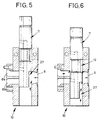
- FIGS. 1 to 4 show the supplemented embodiment of the bolt 11, whereby the previously described with reference to FIGS. 1 to 4 Arrangement can also be used as a starting valve.
- FIG. 5 and 6 are the same components according to FIG. 1st to 4 with the same reference numerals.
- the bolt 11 is equipped with a bypass duct 27, which is arranged so that it is in fluid communication with the Main entry channel 6 can be brought, so that from the main entry channel 6 material coming not to the entry channels 8a or 8b is led, but led away to the atmosphere becomes.
- a bypass duct 27 which is arranged so that it is in fluid communication with the Main entry channel 6 can be brought, so that from the main entry channel 6 material coming not to the entry channels 8a or 8b is led, but led away to the atmosphere becomes.
- Fig. 9 is intended to illustrate that in this rotated position vertical displacement of the bolt 11 is possible, so that for example the connection from the main inlet channel 6 via the Partial inlet channel 8a to the sieve not shown in FIG. 9 is possible but the connection between the main inlet channel 6 is too the inlet sub-channel 8b is blocked.
- FIG. 10 shows that it is possible to do a simple formed locking means 10a with vertically movable Arrange bolts 11a on both sides of the housing 1 so that thus the sieve bolts 2 and 3 arranged in the housing 1 after are lockable on both sides.
Landscapes
- Engineering & Computer Science (AREA)
- Mechanical Engineering (AREA)
- Manufacturing & Machinery (AREA)
- Extrusion Moulding Of Plastics Or The Like (AREA)
Applications Claiming Priority (4)
| Application Number | Priority Date | Filing Date | Title |
|---|---|---|---|
| DE19718598 | 1997-05-02 | ||
| DE19718598 | 1997-05-02 | ||
| DE19730574A DE19730574C1 (de) | 1997-05-02 | 1997-07-17 | Filtereinrichtung für Strangpressen und Spritzgießmaschinen |
| DE19730574 | 1997-07-17 |
Publications (2)
| Publication Number | Publication Date |
|---|---|
| EP0875357A1 true EP0875357A1 (fr) | 1998-11-04 |
| EP0875357B1 EP0875357B1 (fr) | 2001-11-07 |
Family
ID=26036288
Family Applications (1)
| Application Number | Title | Priority Date | Filing Date |
|---|---|---|---|
| EP98101672A Expired - Lifetime EP0875357B1 (fr) | 1997-05-02 | 1998-01-31 | Filtre pour extrudeuses et presses d'injection |
Country Status (2)
| Country | Link |
|---|---|
| EP (1) | EP0875357B1 (fr) |
| AT (1) | ATE208262T1 (fr) |
Cited By (9)
| Publication number | Priority date | Publication date | Assignee | Title |
|---|---|---|---|---|
| EP1245366A3 (fr) * | 1998-04-30 | 2002-10-09 | Kreyenborg Verwaltungen und Beteiligungen GmbH & Co. KG | Mécanisme de blocage pour le contrôle du flux d'un milieu coulant |
| CN102320121A (zh) * | 2011-06-30 | 2012-01-18 | 常州市创信知识产权代理有限公司 | 挤出机用自清洗不停机长效过滤器 |
| EP2065160A3 (fr) * | 2007-11-30 | 2014-10-08 | Kreyenborg Verwaltungen und Beteiligungen GmbH & Co. KG | Dispositif de filtration |
| CN107738431A (zh) * | 2017-11-29 | 2018-02-27 | 河南安吉塑料机械有限公司 | 一种反冲洗网带换网器 |
| WO2020232322A1 (fr) * | 2019-05-15 | 2020-11-19 | Nordson Corporation | Système de filtration de fluide avec vanne de rétrolavage et méthodes de fonctionnement associées |
| CN115674627A (zh) * | 2022-11-02 | 2023-02-03 | 归中智能装备(南通)有限公司 | 一种极性成膜设备及成膜方法 |
| CN116619684A (zh) * | 2023-07-25 | 2023-08-22 | 复星科技集团有限公司 | 一种用于橡胶注射机的胶料过滤结构 |
| US20240009901A1 (en) * | 2022-07-11 | 2024-01-11 | Engel Austria Gmbh | Filter device |
| CN117382031A (zh) * | 2022-07-11 | 2024-01-12 | 恩格尔奥地利有限公司 | 过滤装置 |
Families Citing this family (1)
| Publication number | Priority date | Publication date | Assignee | Title |
|---|---|---|---|---|
| DE102024114848A1 (de) * | 2024-05-27 | 2025-11-27 | Nordson Corporation | Filtriervorrichtung zum Filtrieren eines Fluids sowie betreffende Betriebsverfahren |
Citations (2)
| Publication number | Priority date | Publication date | Assignee | Title |
|---|---|---|---|---|
| US3503096A (en) * | 1945-04-07 | 1970-03-31 | Luigi Marianelli | Continuous-flow filter for extruders and similar machines for processing plastic materials |
| US4096069A (en) * | 1977-02-02 | 1978-06-20 | Postavnichev Vladimir Konstant | Filter for polymer melts and solutions |
-
1998
- 1998-01-31 AT AT98101672T patent/ATE208262T1/de active
- 1998-01-31 EP EP98101672A patent/EP0875357B1/fr not_active Expired - Lifetime
Patent Citations (2)
| Publication number | Priority date | Publication date | Assignee | Title |
|---|---|---|---|---|
| US3503096A (en) * | 1945-04-07 | 1970-03-31 | Luigi Marianelli | Continuous-flow filter for extruders and similar machines for processing plastic materials |
| US4096069A (en) * | 1977-02-02 | 1978-06-20 | Postavnichev Vladimir Konstant | Filter for polymer melts and solutions |
Cited By (14)
| Publication number | Priority date | Publication date | Assignee | Title |
|---|---|---|---|---|
| EP1245366A3 (fr) * | 1998-04-30 | 2002-10-09 | Kreyenborg Verwaltungen und Beteiligungen GmbH & Co. KG | Mécanisme de blocage pour le contrôle du flux d'un milieu coulant |
| EP2065160A3 (fr) * | 2007-11-30 | 2014-10-08 | Kreyenborg Verwaltungen und Beteiligungen GmbH & Co. KG | Dispositif de filtration |
| CN102320121A (zh) * | 2011-06-30 | 2012-01-18 | 常州市创信知识产权代理有限公司 | 挤出机用自清洗不停机长效过滤器 |
| CN102320121B (zh) * | 2011-06-30 | 2014-06-04 | 常州市创信知识产权代理有限公司 | 挤出机用自清洗不停机长效过滤器 |
| CN107738431A (zh) * | 2017-11-29 | 2018-02-27 | 河南安吉塑料机械有限公司 | 一种反冲洗网带换网器 |
| JP2022533123A (ja) * | 2019-05-15 | 2022-07-21 | ノードソン コーポレーション | 逆流洗浄弁を備える流体濾過システム及びその操作方法 |
| WO2020232322A1 (fr) * | 2019-05-15 | 2020-11-19 | Nordson Corporation | Système de filtration de fluide avec vanne de rétrolavage et méthodes de fonctionnement associées |
| US12151187B2 (en) | 2019-05-15 | 2024-11-26 | Nordson Corporation | Fluid filtering system with backflush valve and methods of operating the same |
| US20240009901A1 (en) * | 2022-07-11 | 2024-01-11 | Engel Austria Gmbh | Filter device |
| CN117382031A (zh) * | 2022-07-11 | 2024-01-12 | 恩格尔奥地利有限公司 | 过滤装置 |
| US11992985B2 (en) * | 2022-07-11 | 2024-05-28 | Engel Austria Gmbh | Filter device |
| CN115674627A (zh) * | 2022-11-02 | 2023-02-03 | 归中智能装备(南通)有限公司 | 一种极性成膜设备及成膜方法 |
| CN116619684A (zh) * | 2023-07-25 | 2023-08-22 | 复星科技集团有限公司 | 一种用于橡胶注射机的胶料过滤结构 |
| CN116619684B (zh) * | 2023-07-25 | 2023-10-10 | 复星科技集团有限公司 | 一种用于橡胶注射机的胶料过滤结构 |
Also Published As
| Publication number | Publication date |
|---|---|
| EP0875357B1 (fr) | 2001-11-07 |
| ATE208262T1 (de) | 2001-11-15 |
Similar Documents
| Publication | Publication Date | Title |
|---|---|---|
| EP0577680B1 (fr) | Dispositif de filtrage de fluides a nettoyer | |
| EP0672443B1 (fr) | Dispositif de contrÔle et de filtration d' au moins deux courants partiels de fluide | |
| EP1423178A1 (fr) | Dispositif pour filtrer un fluide, notamment dans des installations de transformation de matieres plastiques | |
| EP0875357B1 (fr) | Filtre pour extrudeuses et presses d'injection | |
| EP0433587A2 (fr) | Dispositif de remplacement de tamis cylindrique | |
| EP0536359B1 (fr) | Module de changement de tamis | |
| EP1082205B1 (fr) | Dispositif de filtration pour extrudeuses et machines a mouler par injection | |
| EP0680815B1 (fr) | Dispositif de filtration pour presses à extruder | |
| DE4218756C1 (en) | Injection moulding machine and extrusion press filter appts. for thermoplastics - comprises barrier member in inlet channel prior to sieve bolt and housing for unimpeded plastic flow in open barrier position, for efficient continual working | |
| EP0798098B1 (fr) | Dispositif de filtrage pour matières plastiques fondues | |
| EP0919353B1 (fr) | Appareil de filtration d'un courant de fluide et un module de filtration à utiliser avec ledit appareil | |
| DE19730574C1 (de) | Filtereinrichtung für Strangpressen und Spritzgießmaschinen | |
| EP1245366B1 (fr) | Mécanisme de blocage pour le contrôle du flux d'un milieu coulant | |
| DE10254022A1 (de) | Vorrichtung zum Filtrieren eines Fluids, insbesondere für kunststoffverarbeitende Anlagen | |
| CH593786A5 (en) | Continuously cleaned filter for extrusion moulder - rotates eccentrically to main feed passage and is cleaned by reverse flow | |
| DE19500060C1 (de) | Filtereinrichtung für Strangpreß- und Spritzgießmaschinen | |
| DE4130002C1 (en) | Distribution point for extrusion press and injection, moulding machine - includes housing, supply unit, vertical bolt unit and inlet connection channel | |
| DE4125181C1 (en) | Filter appts. for extrusion presses, injection moulding machine etc. - includes sieve unit contg. plate(s) having filter candle-cartridges on dirty side | |
| EP1524022B1 (fr) | Dispositif de filtration de liquide, notamment pour des installations de transformation de matières plastiques | |
| DE4408803C1 (de) | Steuereinrichtung für zwei Fluidteilströme | |
| DE4420119C1 (de) | Filtereinrichtung für Strangpressen | |
| DE102004010968B4 (de) | Vorrichtung zum Filtrieren eines Fluids, insbesondere eines verflüssigten Kunststoffes | |
| DE4126261C1 (en) | Simple and reliable filter arrangement for extrusion presses, etc. - including separate channel sectors between inlet and outlet channels and exchangeable sieve carrier, etc. | |
| WO2002016113A2 (fr) | Dispositif pour filtrer des substances liquides, corps support et procede permettant d'actionner ledit dispositif | |
| DE10317170A1 (de) | Vorrichtung zum Filtrieren eines Fluids, insbesondere für kunststoffverarbeitende Anlagen |
Legal Events
| Date | Code | Title | Description |
|---|---|---|---|
| PUAI | Public reference made under article 153(3) epc to a published international application that has entered the european phase |
Free format text: ORIGINAL CODE: 0009012 |
|
| AK | Designated contracting states |
Kind code of ref document: A1 Designated state(s): AT CH DE FR GB IT LI NL |
|
| AX | Request for extension of the european patent |
Free format text: AL;LT;LV;MK;RO;SI |
|
| 17P | Request for examination filed |
Effective date: 19981111 |
|
| AKX | Designation fees paid |
Free format text: AT CH DE FR GB IT LI NL |
|
| GRAG | Despatch of communication of intention to grant |
Free format text: ORIGINAL CODE: EPIDOS AGRA |
|
| 17Q | First examination report despatched |
Effective date: 20010126 |
|
| GRAG | Despatch of communication of intention to grant |
Free format text: ORIGINAL CODE: EPIDOS AGRA |
|
| GRAH | Despatch of communication of intention to grant a patent |
Free format text: ORIGINAL CODE: EPIDOS IGRA |
|
| GRAH | Despatch of communication of intention to grant a patent |
Free format text: ORIGINAL CODE: EPIDOS IGRA |
|
| GRAA | (expected) grant |
Free format text: ORIGINAL CODE: 0009210 |
|
| AK | Designated contracting states |
Kind code of ref document: B1 Designated state(s): AT CH DE FR GB IT LI NL |
|
| REF | Corresponds to: |
Ref document number: 208262 Country of ref document: AT Date of ref document: 20011115 Kind code of ref document: T |
|
| REG | Reference to a national code |
Ref country code: CH Ref legal event code: EP |
|
| REF | Corresponds to: |
Ref document number: 59802020 Country of ref document: DE Date of ref document: 20011213 |
|
| REG | Reference to a national code |
Ref country code: CH Ref legal event code: NV Representative=s name: PATENTANWALTSBUERO EDER AG |
|
| REG | Reference to a national code |
Ref country code: GB Ref legal event code: IF02 |
|
| GBT | Gb: translation of ep patent filed (gb section 77(6)(a)/1977) |
Effective date: 20020114 |
|
| ET | Fr: translation filed | ||
| PLBE | No opposition filed within time limit |
Free format text: ORIGINAL CODE: 0009261 |
|
| STAA | Information on the status of an ep patent application or granted ep patent |
Free format text: STATUS: NO OPPOSITION FILED WITHIN TIME LIMIT |
|
| 26N | No opposition filed | ||
| PGFP | Annual fee paid to national office [announced via postgrant information from national office to epo] |
Ref country code: NL Payment date: 20060119 Year of fee payment: 9 Ref country code: FR Payment date: 20060119 Year of fee payment: 9 |
|
| GBPC | Gb: european patent ceased through non-payment of renewal fee |
Effective date: 20070131 |
|
| NLV4 | Nl: lapsed or anulled due to non-payment of the annual fee |
Effective date: 20070801 |
|
| REG | Reference to a national code |
Ref country code: FR Ref legal event code: ST Effective date: 20070930 |
|
| PG25 | Lapsed in a contracting state [announced via postgrant information from national office to epo] |
Ref country code: GB Free format text: LAPSE BECAUSE OF NON-PAYMENT OF DUE FEES Effective date: 20070131 |
|
| PG25 | Lapsed in a contracting state [announced via postgrant information from national office to epo] |
Ref country code: NL Free format text: LAPSE BECAUSE OF NON-PAYMENT OF DUE FEES Effective date: 20070801 |
|
| PG25 | Lapsed in a contracting state [announced via postgrant information from national office to epo] |
Ref country code: FR Free format text: LAPSE BECAUSE OF NON-PAYMENT OF DUE FEES Effective date: 20070131 |
|
| PGFP | Annual fee paid to national office [announced via postgrant information from national office to epo] |
Ref country code: GB Payment date: 20060123 Year of fee payment: 9 |
|
| PGFP | Annual fee paid to national office [announced via postgrant information from national office to epo] |
Ref country code: CH Payment date: 20110125 Year of fee payment: 14 Ref country code: AT Payment date: 20110120 Year of fee payment: 14 Ref country code: DE Payment date: 20101126 Year of fee payment: 14 Ref country code: IT Payment date: 20110126 Year of fee payment: 14 |
|
| REG | Reference to a national code |
Ref country code: CH Ref legal event code: PL |
|
| PG25 | Lapsed in a contracting state [announced via postgrant information from national office to epo] |
Ref country code: DE Free format text: LAPSE BECAUSE OF NON-PAYMENT OF DUE FEES Effective date: 20120801 Ref country code: LI Free format text: LAPSE BECAUSE OF NON-PAYMENT OF DUE FEES Effective date: 20120131 Ref country code: CH Free format text: LAPSE BECAUSE OF NON-PAYMENT OF DUE FEES Effective date: 20120131 |
|
| REG | Reference to a national code |
Ref country code: DE Ref legal event code: R119 Ref document number: 59802020 Country of ref document: DE Effective date: 20120801 |
|
| PG25 | Lapsed in a contracting state [announced via postgrant information from national office to epo] |
Ref country code: IT Free format text: LAPSE BECAUSE OF NON-PAYMENT OF DUE FEES Effective date: 20120131 |
|
| REG | Reference to a national code |
Ref country code: AT Ref legal event code: MM01 Ref document number: 208262 Country of ref document: AT Kind code of ref document: T Effective date: 20120131 |
|
| PG25 | Lapsed in a contracting state [announced via postgrant information from national office to epo] |
Ref country code: AT Free format text: LAPSE BECAUSE OF NON-PAYMENT OF DUE FEES Effective date: 20120131 |