EP0875436A2 - Betätigungsvorrichtung für Federspeicherfeststellbremse mit hülsenartigem Spielnachsteller - Google Patents
Betätigungsvorrichtung für Federspeicherfeststellbremse mit hülsenartigem Spielnachsteller Download PDFInfo
- Publication number
- EP0875436A2 EP0875436A2 EP98101664A EP98101664A EP0875436A2 EP 0875436 A2 EP0875436 A2 EP 0875436A2 EP 98101664 A EP98101664 A EP 98101664A EP 98101664 A EP98101664 A EP 98101664A EP 0875436 A2 EP0875436 A2 EP 0875436A2
- Authority
- EP
- European Patent Office
- Prior art keywords
- sleeve
- piston
- stem
- hollow stem
- parking brake
- Prior art date
- Legal status (The legal status is an assumption and is not a legal conclusion. Google has not performed a legal analysis and makes no representation as to the accuracy of the status listed.)
- Granted
Links
- 244000273618 Sphenoclea zeylanica Species 0.000 claims abstract description 21
- 239000012530 fluid Substances 0.000 claims abstract description 19
- 238000005192 partition Methods 0.000 description 2
- 230000006978 adaptation Effects 0.000 description 1
- 230000007246 mechanism Effects 0.000 description 1
- 230000004048 modification Effects 0.000 description 1
- 238000012986 modification Methods 0.000 description 1
- 230000004044 response Effects 0.000 description 1
Images


Classifications
-
- B—PERFORMING OPERATIONS; TRANSPORTING
- B61—RAILWAYS
- B61H—BRAKES OR OTHER RETARDING DEVICES SPECIALLY ADAPTED FOR RAIL VEHICLES; ARRANGEMENT OR DISPOSITION THEREOF IN RAIL VEHICLES
- B61H15/00—Wear-compensating mechanisms, e.g. slack adjusters
-
- B—PERFORMING OPERATIONS; TRANSPORTING
- B60—VEHICLES IN GENERAL
- B60T—VEHICLE BRAKE CONTROL SYSTEMS OR PARTS THEREOF; BRAKE CONTROL SYSTEMS OR PARTS THEREOF, IN GENERAL; ARRANGEMENT OF BRAKING ELEMENTS ON VEHICLES IN GENERAL; PORTABLE DEVICES FOR PREVENTING UNWANTED MOVEMENT OF VEHICLES; VEHICLE MODIFICATIONS TO FACILITATE COOLING OF BRAKES
- B60T17/00—Component parts, details, or accessories of power brake systems not covered by groups B60T8/00, B60T13/00 or B60T15/00, or presenting other characteristic features
- B60T17/08—Brake cylinders other than ultimate actuators
- B60T17/083—Combination of service brake actuators with spring loaded brake actuators
-
- F—MECHANICAL ENGINEERING; LIGHTING; HEATING; WEAPONS; BLASTING
- F16—ENGINEERING ELEMENTS AND UNITS; GENERAL MEASURES FOR PRODUCING AND MAINTAINING EFFECTIVE FUNCTIONING OF MACHINES OR INSTALLATIONS; THERMAL INSULATION IN GENERAL
- F16D—COUPLINGS FOR TRANSMITTING ROTATION; CLUTCHES; BRAKES
- F16D65/00—Parts or details
- F16D65/14—Actuating mechanisms for brakes; Means for initiating operation at a predetermined position
Definitions
- the present invention relates to a novel parking brake actuator that can be incorporated in the service brake actuator disclosed in U.S. Patent 5,423,412 to Lewis Arthur et al., which patent is assigned to the assignee of the present application.
- the Arthur et al. patent discloses a pneumatic actuator having a single service piston that applies the braking mechanisms of passenger railway transit vehicles and the like.
- the service piston of Arthur et al. has a hollow stem located around a threaded shaft provided with power and brake adjusting collets threaded on the shaft.
- the brake adjusting collet provides adjustment for excess wear of brake shoe and other components of the transit vehicle.
- the disclosure of the Arthur patent is incorporated herein by reference.
- the present invention adds a pneumatic parking brake feature to the brake actuator and service piston of the Essen et al. patent. This is accomplished by locating a second piston in front of the service piston and around the hollow stem of the service piston.
- a coil spring is located between a forward wall of a housing portion containing the second piston and a locking ring seated in a circumferential groove provided in a forward sleeve. When pressurized fluid is removed from the housing portion containing the second piston, the piston and forward sleeve move forward to engage the hollow stem of the service piston thereby forwardly translating the hollow stem.
- Such forward translation of the hollow stem causes a conical bearing surface on the stem to engage the power collet located on the threaded shaft that, when thrust forwardly, operates braking means located on the railway vehicle, i.e., the conical surface acting upon the collet thrusts the threaded rod forwardly to apply the brakes of the vehicle.
- a primary objective of the present invention is to provide a pneumatic dynamic braking system with a parking brake application.
- Another objective of the invention is to provide the above parking brake application in combination with an adjustable collet that allows adjustment to the brake actuator in response to wear of braking components.
- FIG. 1 shows a fluid operated actuator 10 of the invention in longitudinal section.
- Actuator 10 includes hollow cylindrical housing portions 12 and 13 containing respectively a service piston 14 and a parking brake piston 16. Housing portions 12 and 13 can be secured together by bolts (not visible in the drawings) to provide a generally unitary housing structure. Between the pistons is a wall portion 17 that separates the housing portions into sealed compartments 18 and 19 which house respectfully pistons 14 and 16.
- Service piston 14 is connected to an inner hollow stem 20 while parking brake piston 16 is connected to an outer hollow sleeve 21 surrounding stem 20.
- At the forward end of actuator 10 and inside of the forward end of sleeve 21 is an additional sleeve 22.
- Sleeve 22 is disposed about an adjustable collet 24.
- Collet 24 is seated on an internally located threaded rod 26 that operates the braking apparatus (not shown) of a railway type vehicle when rod 26 is thrust outwardly from the actuator by service piston 14 or by a relatively large coil spring 28 located about outer sleeve 21.
- the spring has a right hand end (in the drawings) seated in a recess 29 provided in a forward wall 30 of housing 13.
- the spring is held between the forward wall 30 of housing 13 and a circular spring seat 31 held in place by a retaining ring 32 located on outer sleeve 21.
- a locking ring 34 is situated in front of the forward end of outer sleeve 21 and seats in a circumferential groove 35 provided in the external surface of forward sleeve 22.
- the forward end of sleeve 21 is shown abutting against a circular housing structure 37 surrounding ring 34.
- Housing 37and spring seat 31 are secured together in a manner no visible in the Figure.
- the housing and seat can, for example, be bolted
- a second, power collet 36 is also located onto rod 26 at a location behind adjustable collet 24.
- Collet 36 has a conical bearing surface 38 that faces outwardly toward corresponding conical bearing surface 40 of stem 20.
- collet 36 and stem 20 have respective abutting ledges 44 and 45 at a location behind conical surfaces 38 and 40.
- An intermediate sleeve 42 is located between outer sleeve 21 and hollow stem 20. Intermediate sleeve 42 is provided with an inwardly directed boss 46 that seats behind a retaining ring 47 located on inner stem 20.
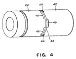
- the forward end of the intermediate sleeve and the rearward end of forward sleeve 22 are respectively provided with integral longitudinal teeth 49 sized to mate together, as shown in Figure 4.
- the teeth are provided with circumferential grooves that are aligned when the teeth are suitably mated such that a second retaining ring 48 is seatable in the circumferential groove, as shown in Figure 4, which locks the sleeves together.
- a second coil spring 50 is located in compartment 18, between partition 17 and a closed end wall of 52 cylindrical housing 12, for returning piston 14 to the end wall when fluid pressure is removed from compartment 18.
- the parking brake portion of actuator 10 operates in the following manner.
- fluid pressure is removed from service piston 14 such that spring 50 maintains the piston against end wall 52.
- An appropriate pressurized fluid such as air, is sent to compartment 19 of actuator 10 through a port 54 provided in forward wall 30 of cylinder 13 from a source of pressurized fluid (not shown). The fluid pressure is applied to the forward face of piston 16 forcing the piston to the rear of compartment 19 and toward partition 17, as shown further in Figure 2.
- Spring 28 maintains parking brake application until fluid pressure is reapplied to piston 16 via port 54.
- piston 16 is returned to the rear of housing 13 and outer sleeve is moved with the piston to compress spring 28 and return center rod 26 to a non-parking brake application in the manner described above in reference Figure 2 of the drawings.
- the service brake operates with the application of fluid pressure to compartment 18 via port 58 in housing 12.
- the fluid pressure is directed between the piston and rearwall 52 of the housing to drive the piston in a forward direction, as seen in Figure 3.
- Forward movement of the piston translates inner stem 20 forwardly such that its conical surface 40 engage conical surface 38 of collet 36 to drive threaded rod 26 into engagement with braking components of the vehicle.
- the service brakes remain applied until fluid pressure is removed from compartment 18 and return spring 50 expands to move piston 14 to the rear of housing 12.
Landscapes
- Engineering & Computer Science (AREA)
- Mechanical Engineering (AREA)
- General Engineering & Computer Science (AREA)
- Transportation (AREA)
- Braking Arrangements (AREA)
- Transmission Of Braking Force In Braking Systems (AREA)
- Braking Systems And Boosters (AREA)
Applications Claiming Priority (2)
| Application Number | Priority Date | Filing Date | Title |
|---|---|---|---|
| US08/850,599 US5937974A (en) | 1997-05-02 | 1997-05-02 | Spring applied parking brake actuator having a collet style slack adjuster |
| US850599 | 2001-05-07 |
Publications (3)
| Publication Number | Publication Date |
|---|---|
| EP0875436A2 true EP0875436A2 (de) | 1998-11-04 |
| EP0875436A3 EP0875436A3 (de) | 1999-04-14 |
| EP0875436B1 EP0875436B1 (de) | 2003-05-28 |
Family
ID=25308600
Family Applications (1)
| Application Number | Title | Priority Date | Filing Date |
|---|---|---|---|
| EP98101664A Expired - Lifetime EP0875436B1 (de) | 1997-05-02 | 1998-01-31 | Betätigungsvorrichtung für Federspeicherfeststellbremse mit hülsenartigem Spielnachsteller |
Country Status (6)
| Country | Link |
|---|---|
| US (1) | US5937974A (de) |
| EP (1) | EP0875436B1 (de) |
| JP (1) | JP3088699B2 (de) |
| AU (1) | AU720387B2 (de) |
| CA (1) | CA2217245C (de) |
| DE (1) | DE69814980T2 (de) |
Cited By (4)
| Publication number | Priority date | Publication date | Assignee | Title |
|---|---|---|---|---|
| CN103717935A (zh) * | 2011-07-26 | 2014-04-09 | 纳博特斯克有限公司 | 单元制动器 |
| CN105465239A (zh) * | 2014-09-19 | 2016-04-06 | 鞍钢股份有限公司 | 一种制动器制动装置及方法 |
| CN108006112A (zh) * | 2018-01-02 | 2018-05-08 | 中车株洲电力机车有限公司 | 一种制动系统 |
| WO2020237775A1 (zh) * | 2019-05-30 | 2020-12-03 | 眉山中车制动科技股份有限公司 | 车辆制动停放装置 |
Families Citing this family (22)
| Publication number | Priority date | Publication date | Assignee | Title |
|---|---|---|---|---|
| AUPO478597A0 (en) * | 1997-01-24 | 1997-02-20 | Woollams, John | Automatic adjuster for spring applied mechanisms |
| US6397986B2 (en) * | 1999-09-23 | 2002-06-04 | Westinghouse Air Brake Technologies Corporation | Collet style tread brake unit |
| US6378668B1 (en) * | 2000-02-24 | 2002-04-30 | Westinghouse Air Brake Company | Spring applied parking brake assembly having a manual quick release feature |
| US6702072B2 (en) * | 2002-04-18 | 2004-03-09 | Westinghouse Air Brake Technologies Corporation | Brake cylinder unit |
| JP3794485B2 (ja) | 2002-06-26 | 2006-07-05 | 三菱電機株式会社 | 内燃機関の気筒判別装置 |
| SE523553C2 (sv) * | 2002-07-04 | 2004-04-27 | Haldex Brake Prod Ab | Fluidaktiverad parkeringsbroms |
| US6902043B2 (en) | 2002-12-13 | 2005-06-07 | Indian Head Industries, Inc. | Driveline vehicle parking brake actuator |
| US7249659B2 (en) * | 2004-01-08 | 2007-07-31 | New York Air Brake Corporation | Fluid actuator |
| US9623855B2 (en) * | 2004-01-08 | 2017-04-18 | New York Air Brake Llc | Parking brake system including a brake cylinder |
| US7493994B2 (en) * | 2004-12-16 | 2009-02-24 | Bendix Spicer Foundation Brake Llc | Spring brake actuator with mid-located spring |
| SE529112C2 (sv) * | 2005-09-30 | 2007-05-02 | Faiveley Transport Nordic Ab | Bromsenhet för ett rälsfordon |
| WO2007067199A1 (en) * | 2005-12-05 | 2007-06-14 | Wabtec Holding Corporation | Collet controlled slack adjuster |
| JP4809282B2 (ja) * | 2007-04-12 | 2011-11-09 | ナブテスコ株式会社 | ブレーキシリンダ装置及びブレーキキャリパ装置 |
| US7926628B2 (en) * | 2008-06-12 | 2011-04-19 | Wabtec Holding Corp. | Spring-applied parking brake with manual release and reapply |
| DE102008051679B4 (de) * | 2008-10-15 | 2016-07-07 | Knorr-Bremse Systeme für Schienenfahrzeuge GmbH | Pneumatischer Bremszylinder |
| US8082645B2 (en) * | 2008-12-08 | 2011-12-27 | Wabtec Holding Corp. | Rotary manual release |
| US8360214B2 (en) * | 2009-04-09 | 2013-01-29 | Wabtec Holding Corp. | Brake shoe support assembly and method |
| RU2510343C1 (ru) * | 2012-08-09 | 2014-03-27 | Зао Научно-Проектный Центр "Тормоз" (Зао Нпц "Тормоз") | Тормозной цилиндр единицы подвижного состава |
| US9889833B2 (en) * | 2012-10-18 | 2018-02-13 | Performance Friction Corporation | Integrated parking brake for disk brake |
| CN112879474B (zh) * | 2021-01-04 | 2022-08-16 | 中车青岛四方车辆研究所有限公司 | 气动制动缸及制动夹钳单元 |
| EP4086127A1 (de) | 2021-05-06 | 2022-11-09 | ZF CV Systems Europe BV | Federspeicherbremszylinder |
| CN115217869B (zh) * | 2022-07-18 | 2023-09-08 | 广州大学 | 一种新型停放制动装置 |
Citations (1)
| Publication number | Priority date | Publication date | Assignee | Title |
|---|---|---|---|---|
| US5423412A (en) | 1994-02-08 | 1995-06-13 | Tsubakimoto Chain Co. | Rubber tire separation and transport apparatus |
Family Cites Families (12)
| Publication number | Priority date | Publication date | Assignee | Title |
|---|---|---|---|---|
| DE2800449C3 (de) | 1978-01-05 | 1980-12-04 | Knorr-Bremse Gmbh, 8000 Muenchen | Schneilösevorrichtung für Federspeicherbremszylinder mit Dämpfungseinrichtung |
| FR2472496A1 (fr) * | 1979-12-28 | 1981-07-03 | Wabco Westinghouse | Cylindre de frein a deux pistons |
| US4364305A (en) * | 1980-06-09 | 1982-12-21 | Wabco Westinghouse, S.A. | Brake cylinder device combining a pneumatically-applied service brake and a spring-applied parking brake |
| FR2492330A1 (fr) * | 1980-10-21 | 1982-04-23 | Wabco Westinghouse | Cylindre de frein a deux pistons |
| US4361078A (en) * | 1981-03-16 | 1982-11-30 | Wabco Ltd. | Hydraulic brake actuator having spring-applied back-up brake with manual release means |
| US4478319A (en) * | 1983-01-28 | 1984-10-23 | Wabco Westinghouse Compagnia Freni S.P.A. | Spring-applied brake unit for railway vehicle with manual release arrangement |
| DE3411054A1 (de) * | 1984-03-26 | 1985-10-03 | Wabco Westinghouse Steuerungstechnik GmbH & Co, 3000 Hannover | Mechanische loeseeinrichtung fuer einen federspeicherbremszylinder |
| SE451008B (sv) | 1985-12-03 | 1987-08-24 | Sab Nife Ab | Fjederbromsaktuator for en bromsenhet |
| JPH0348933Y2 (de) * | 1986-03-28 | 1991-10-18 | ||
| SE454428B (sv) | 1986-09-08 | 1988-05-02 | Sab Nife Ab | Lasringsanordning i fjederbromsaktuator for att avbryta och automatiskt ateruppretta arbetsfunktionen |
| US5423401A (en) * | 1994-04-07 | 1995-06-13 | Westinghouse Air Brake Company | Brake actuator having collet style slack adjuster |
| DE4445960C1 (de) * | 1994-12-22 | 1996-07-11 | Grau Gmbh | Bremszylinder für eine druckluftbetätigte Fahrzeugbremse |
-
1997
- 1997-05-02 US US08/850,599 patent/US5937974A/en not_active Expired - Lifetime
- 1997-10-02 CA CA002217245A patent/CA2217245C/en not_active Expired - Fee Related
-
1998
- 1998-01-28 AU AU52825/98A patent/AU720387B2/en not_active Expired
- 1998-01-31 DE DE69814980T patent/DE69814980T2/de not_active Expired - Lifetime
- 1998-01-31 EP EP98101664A patent/EP0875436B1/de not_active Expired - Lifetime
- 1998-05-01 JP JP10122335A patent/JP3088699B2/ja not_active Expired - Fee Related
Patent Citations (1)
| Publication number | Priority date | Publication date | Assignee | Title |
|---|---|---|---|---|
| US5423412A (en) | 1994-02-08 | 1995-06-13 | Tsubakimoto Chain Co. | Rubber tire separation and transport apparatus |
Cited By (6)
| Publication number | Priority date | Publication date | Assignee | Title |
|---|---|---|---|---|
| CN103717935A (zh) * | 2011-07-26 | 2014-04-09 | 纳博特斯克有限公司 | 单元制动器 |
| CN103717935B (zh) * | 2011-07-26 | 2016-03-30 | 纳博特斯克有限公司 | 单元制动器 |
| CN105465239A (zh) * | 2014-09-19 | 2016-04-06 | 鞍钢股份有限公司 | 一种制动器制动装置及方法 |
| CN108006112A (zh) * | 2018-01-02 | 2018-05-08 | 中车株洲电力机车有限公司 | 一种制动系统 |
| CN108006112B (zh) * | 2018-01-02 | 2020-02-11 | 中车株洲电力机车有限公司 | 一种制动系统 |
| WO2020237775A1 (zh) * | 2019-05-30 | 2020-12-03 | 眉山中车制动科技股份有限公司 | 车辆制动停放装置 |
Also Published As
| Publication number | Publication date |
|---|---|
| EP0875436B1 (de) | 2003-05-28 |
| DE69814980D1 (de) | 2003-07-03 |
| DE69814980T2 (de) | 2004-05-19 |
| CA2217245A1 (en) | 1998-11-02 |
| AU720387B2 (en) | 2000-06-01 |
| JP3088699B2 (ja) | 2000-09-18 |
| EP0875436A3 (de) | 1999-04-14 |
| AU5282598A (en) | 1998-11-05 |
| US5937974A (en) | 1999-08-17 |
| CA2217245C (en) | 2001-05-29 |
| JPH1159391A (ja) | 1999-03-02 |
Similar Documents
| Publication | Publication Date | Title |
|---|---|---|
| US5937974A (en) | Spring applied parking brake actuator having a collet style slack adjuster | |
| US4364305A (en) | Brake cylinder device combining a pneumatically-applied service brake and a spring-applied parking brake | |
| CA2188107C (en) | Pneumatic pressure operated parking brake for a railway vehicle brake system | |
| EP1127766A3 (de) | Federkraftbetätigte Feststellbremse | |
| US3782251A (en) | Spring brake with manual release mechanism | |
| US3371753A (en) | Hydraulic quick-slack-take-up pulsator for disk brakes | |
| US3896706A (en) | Brake actuator units | |
| US4631924A (en) | Dual-circuit master cylinder having auxiliary piston and yoke with equalization chambers for hydraulic equalization | |
| US4412603A (en) | Dual pressure, dual piston actuator | |
| US4945728A (en) | Center compensating tandem master cylinder with seals in cylinder wall | |
| CA2332666A1 (en) | Spring applied parking brake assembly | |
| EP0676557B1 (de) | Bremsbetätiger mit hülsenartigem Spielnachsteller | |
| US3490565A (en) | Piston assembly for dual-network disk-brake system | |
| US7168536B2 (en) | Brake master cylinder comprising plunger pistons and radial grooves inserted into the housing in order to receive sealing joints | |
| US3601233A (en) | Piston assembly for dual-network disk-brake system | |
| US4263784A (en) | Power brake unit for automotive vehicles | |
| US5099965A (en) | Rail braking actuation device | |
| US3406522A (en) | Master piston actuator | |
| US20070039787A1 (en) | Static/dynamic pressure-energized seal for a brake actuator | |
| US5713261A (en) | Slack adjustable force transmitting cylinder | |
| US6325181B1 (en) | Piston assembly for use in a wheel cylinder of a drum brake assembly | |
| GB2082678A (en) | An hydraulic actuator for a vehicle internal shoe-drum brake | |
| US3336597A (en) | Master piston actuator | |
| US3669226A (en) | Piston assembly for dual-network disk-brake system | |
| US5878574A (en) | Master cylinder having nested concentric pistons |
Legal Events
| Date | Code | Title | Description |
|---|---|---|---|
| PUAI | Public reference made under article 153(3) epc to a published international application that has entered the european phase |
Free format text: ORIGINAL CODE: 0009012 |
|
| AK | Designated contracting states |
Kind code of ref document: A2 Designated state(s): DE FR GB SE |
|
| AX | Request for extension of the european patent |
Free format text: AL;LT;LV;MK;RO;SI |
|
| PUAL | Search report despatched |
Free format text: ORIGINAL CODE: 0009013 |
|
| AK | Designated contracting states |
Kind code of ref document: A3 Designated state(s): AT BE CH DE DK ES FI FR GB GR IE IT LI LU MC NL PT SE |
|
| AX | Request for extension of the european patent |
Free format text: AL;LT;LV;MK;RO;SI |
|
| 17P | Request for examination filed |
Effective date: 19990525 |
|
| AKX | Designation fees paid |
Free format text: DE FR GB SE |
|
| 17Q | First examination report despatched |
Effective date: 20020326 |
|
| GRAH | Despatch of communication of intention to grant a patent |
Free format text: ORIGINAL CODE: EPIDOS IGRA |
|
| RIN1 | Information on inventor provided before grant (corrected) |
Inventor name: MOORE, ROLAND S. Inventor name: CATHCART, CHRISTOPHER A. |
|
| GRAH | Despatch of communication of intention to grant a patent |
Free format text: ORIGINAL CODE: EPIDOS IGRA |
|
| GRAA | (expected) grant |
Free format text: ORIGINAL CODE: 0009210 |
|
| AK | Designated contracting states |
Designated state(s): DE FR GB SE |
|
| REG | Reference to a national code |
Ref country code: GB Ref legal event code: FG4D |
|
| REF | Corresponds to: |
Ref document number: 69814980 Country of ref document: DE Date of ref document: 20030703 Kind code of ref document: P |
|
| REG | Reference to a national code |
Ref country code: SE Ref legal event code: TRGR |
|
| ET | Fr: translation filed | ||
| PLBE | No opposition filed within time limit |
Free format text: ORIGINAL CODE: 0009261 |
|
| STAA | Information on the status of an ep patent application or granted ep patent |
Free format text: STATUS: NO OPPOSITION FILED WITHIN TIME LIMIT |
|
| 26N | No opposition filed |
Effective date: 20040302 |
|
| REG | Reference to a national code |
Ref country code: FR Ref legal event code: PLFP Year of fee payment: 19 |
|
| REG | Reference to a national code |
Ref country code: FR Ref legal event code: PLFP Year of fee payment: 20 |
|
| PGFP | Annual fee paid to national office [announced via postgrant information from national office to epo] |
Ref country code: FR Payment date: 20161229 Year of fee payment: 20 |
|
| PGFP | Annual fee paid to national office [announced via postgrant information from national office to epo] |
Ref country code: DE Payment date: 20170125 Year of fee payment: 20 Ref country code: SE Payment date: 20170111 Year of fee payment: 20 |
|
| PGFP | Annual fee paid to national office [announced via postgrant information from national office to epo] |
Ref country code: GB Payment date: 20170125 Year of fee payment: 20 |
|
| REG | Reference to a national code |
Ref country code: DE Ref legal event code: R071 Ref document number: 69814980 Country of ref document: DE |
|
| REG | Reference to a national code |
Ref country code: GB Ref legal event code: PE20 Expiry date: 20180130 |
|
| PG25 | Lapsed in a contracting state [announced via postgrant information from national office to epo] |
Ref country code: GB Free format text: LAPSE BECAUSE OF EXPIRATION OF PROTECTION Effective date: 20180130 |