EP0875437A2 - Zugsensor zur Warnung von Personen im Gleisbereich - Google Patents
Zugsensor zur Warnung von Personen im Gleisbereich Download PDFInfo
- Publication number
- EP0875437A2 EP0875437A2 EP98107174A EP98107174A EP0875437A2 EP 0875437 A2 EP0875437 A2 EP 0875437A2 EP 98107174 A EP98107174 A EP 98107174A EP 98107174 A EP98107174 A EP 98107174A EP 0875437 A2 EP0875437 A2 EP 0875437A2
- Authority
- EP
- European Patent Office
- Prior art keywords
- pressure
- evaluator
- pressure chamber
- train
- tension sensor
- Prior art date
- Legal status (The legal status is an assumption and is not a legal conclusion. Google has not performed a legal analysis and makes no representation as to the accuracy of the status listed.)
- Withdrawn
Links
Images
Classifications
-
- B—PERFORMING OPERATIONS; TRANSPORTING
- B61—RAILWAYS
- B61L—GUIDING RAILWAY TRAFFIC; ENSURING THE SAFETY OF RAILWAY TRAFFIC
- B61L1/00—Devices along the route controlled by interaction with the vehicle or train
- B61L1/02—Electric devices associated with track, e.g. rail contacts
- B61L1/04—Electric devices associated with track, e.g. rail contacts mechanically actuated by a part of the vehicle
-
- B—PERFORMING OPERATIONS; TRANSPORTING
- B61—RAILWAYS
- B61L—GUIDING RAILWAY TRAFFIC; ENSURING THE SAFETY OF RAILWAY TRAFFIC
- B61L23/00—Control, warning or like safety means along the route or between vehicles or trains
- B61L23/06—Control, warning or like safety means along the route or between vehicles or trains for warning men working on the route
Definitions
- the invention relates to a train sensor for warning people in the track area.
- Train sensors for warning people in the track area against approaching trains are known, the signals of which are used for warning purposes are routed via a message channel to warning stations located in the work area of people and which issue a warning in accordance with the signals (LENGEMANN, From detection to alarm - the future rot warning at the Deutsche Bureaubahn "in electric railways, 1983, H.6, p.204-209; DE-AS 1 755 589).
- Inductive sensors or vibration sensors are called.
- Vibration sensors are unsuitable
- a mechanic has to laboriously adapt the inductive sensors to the type of rail, mount them on the rail and adjust them, and the mechanic himself has to warn of the approaching trains In the case of slowly moving construction sites, this necessary safeguard no longer provides the benefit of a warning system, and inductive sensors are also susceptible to magnetic fields from brakes and drive currents, and it is not possible to detect wheels made of non-ferrous metal.
- a pneumatic train sensor is known (SIEMENS: Elektrotechnik im railway operation, S44 rail current closer, SH 3226 / 2561.5 T ES), one has 4 pressure claws attached to the rail pressure chamber, with Driving over a pulling wheel creates a pressure in the pressure chamber via a The hose is electrically isolated from a membrane contact that detects the tension becomes. Installation and time-consuming adjustment must be carried out in the danger area will. There are no means to control the fall of the tension sensor from the rail called.
- Measuring devices for determining the weight of railway vehicles are known from DE-PS 822 019, the deflection of the rail being measured as a result of the weight on the train wheel with a pressure chamber screwed to the rail foot.
- the pressure changes can act directly on control devices.
- the nearest sleepers are fixed and stiffened for the correct functioning of the pressure chamber. But the scripture does not address what is known from it Weight measurement principle "to apply to a device for warning people. Safety principles are not specified.
- the object of the invention is to provide a tension sensor, the signals of which it it is possible to warn people in the track area of approaching trains, whereby the Train sensor has the required security and can be installed safely and quickly can be.
- the tension sensor is simply constructed. To assemble you do not have to Keep the danger zone open, as there is no need to screw it onto the rail. A Adjustment in the danger zone is not necessary.
- the Monitoring the pressure ensures detection of failure or failure dangerous removal of the tension sensor.
- Guides on the top of the train sensor prevent slipping sideways.
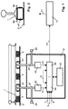
- a travel rail 1 is supported by sleepers 3 on a substructure 2.
- both the running rail 1 and the sleepers 3 and the substructure 2 under the sleepers 3 are loaded.
- the distance of the rail foot to the substructure 2 changes most in the middle between the sleepers 3 and is significantly greater than the deflection of the running rail 1 alone.
- This property is used in the tension sensor for obtaining trouble-free, large pressure changes in pressure chambers 21, 41 by pushing the pressure chambers 21, 41 in at this point.
- the pushing in of the pressure chamber 21, 41 under the rail foot can be done with a handle in a depressurized cylinder and without exposing itself to any danger.
- the pressure chamber 21, 41 is then filled until the desired pressure is established, or the pressure chamber 21, 41 is clamped non-positively between the foot of the travel rail 1 and the substructure 2. An attachment to the rail is not necessary. An adjustment to the rail type and an adjustment is not necessary.
- the remaining components 13 of the train sensor are expediently combined in a housing located away from the track; they are not electrically connected to the running rail 1 and are therefore not exposed to disturbances from drive currents and magnetic fields.
- the pressure chamber 21, 41 is connected to a pressure sensor 23, 43 via a pressure hose 27, 47. Electrical signals 31, 51 are present at the pressure sensor in proportion to the pressure in the pressure chamber 21, 41, which are fed to an evaluator 5 a, 5 b.
- the pressure signals 31, 51 change positively when the pressure chamber 21, 41 is loaded by a pull wheel. When the load is relieved after driving over, there is a negative change in the pressure signal 31.51. These pressure changes are evaluated as a wheel signal by the evaluator 5a, 5b if the pressure change exceeds a value of a pressure change 7 given to the evaluator 5a, 5b at its input, either in a positive or negative direction; this protects against disturbances and pediatric interference.
- the positive pressure change is preferred because it also detects stationary traction wheels.
- a wheel signal recognized in this way is passed in a known manner by the evaluator 5a, 5b via a wired or wireless message channel 11 to warning stations 15, which emit a warning 17 directly or indirectly according to the signals of the message channel 11 to the persons to be warned in the track area.
- a train sensor 21, 41, 13 can, for example, announce the train, another train sensor 21, 41, 13, not shown, in the vicinity of the persons to be warned can de-register the train by both train sensors acting on the warning station 15.
- a revolving counter 10 can count the wheel signals and the evaluator 5a, 5b Submit payer status via message channel 11. In this way, trains can be recorded more precisely.
- the direction of pull can also be detected by the evaluator 5a, 5b by the evaluator 5a the wheel signals from the train sensor 21, 23 and the evaluator 5b the bath signals from adjacent tension sensor 41,43 detected.
- the time sequence of the wheel signals is a measure of the direction of the train which the evaluator 5a, 5b delivers directly to the message channel 11 or linked as a sign with the counter reading 10.
- train sensors 21, 41, 13 complex track diagrams during the detection be ruled by trains.
- the safety-relevant parts 23, 5a and 43.5b of the tension sensor are expediently closed double and the results of the evaluator 5a with those of the evaluator 5b over a Compound 6 to compare in time, with a waiting period 8 at the entrance of the Evaluator 5a, 5b is specified.
- the evaluator 5a, 5b determines an inequality after the waiting period 8 and enters Fault signal to the message channel 11.
- a tension sensor can be used in the same way secure with only one pressure chamber 21, this pressure chamber with both Pressure sensors 23 and 43 is connected (not shown).
- the assembly is much easier if the pressure chambers 21, 41 and Pressure sensors 23.43 with closable filling openings 25.45 for a liquid or gaseous medium are connected and the pressure chambers 21, 41 as lifting cylinders, are preferably designed as bellows cylinders.
- FIG. 2 shows a typical arrangement of a pressure chamber 21, 41 between the foot of the running rail 1 and the substructure 2.
- Guides 64 on the upper side of the pressure chamber 21, 41 adapted to the foot of the travel rail 1 prevent the pressure chamber 21, 41 from slipping sideways and further facilitate assembly.
Landscapes
- Engineering & Computer Science (AREA)
- Mechanical Engineering (AREA)
- Automation & Control Theory (AREA)
- Train Traffic Observation, Control, And Security (AREA)
- Force Measurement Appropriate To Specific Purposes (AREA)
Abstract
Description
Claims (7)
- Zugsensor zur Warnung von Personen im Gleisbereich vor herannahenden Zügen, dessen der Warngebung dienende Signale über einen Nachrichtenkanal (11) an im Arbeitsbereich von Personen gelegene Wamstationen (15) geleitet werden, die entsprechend den Signalen eine Warnung (17) abgeben, wobeider Zugsensor eine geschlossene Druckkammer (21,41), einen Drucksensor (23,43) und einen Auswerter (5a,5b) aufweist,die Druckkammer (21,41) zwischen dem Fuß der Fahrschiene (1) und einem Unterbau (2) angeordnet ist,die Druckkammer (21,41) über einen Schlauch (27,47) mit einem Drucksensor (23,43) verbunden und dessen Ausgangssignale (31,51) an den Auswerter (5a,5b) geführt sind,die Änderung des Druckes in der Druckkammer (21,41) infolge der Be- und/oder Entlastung bei dem Überfahren eines Zugrades vom Drucksensor (23,43) erfaßt und an den Auswerter (5a,5b) geleitet wird, undder Auswerter (5a,5b) ein Überschreiten der Druckänderung über einen dem Auswerter (5a,5b) vorgegebenen Wert einer Druckänderung (7) als ein das Rad kennzeichnendes Radsignal wertet und an den Nachrichtenkanal (11) abgibt,die Druckkammer (21,41) nach dem Einschieben zwischen dem Fuß der Fahrschiene (1) und dem Unterbau (2) durch Beaufschlagung der Druckkammer (21,41) mit Überdruck ohne Hilfe von Befestigungsmitteln kraftschlüssig festklemmt.
- Zugsensor nach Anspruch 1, dadurch gekennzeichnet,daß der Auswerter (5a,5b) bei Absinken des Druckes unter einen dem Auswerter (5a,5b) vorgegebenen Druckwert (9) ein Störungssignal an den Nachrichtenkanal (11) abgibt.
- Zugsensor nach einem der vorhergehenden Ansprüche, dadurch gekennzeichnet,daß der Zugsensor eine verschließbare Füllöffung (25,45) aufweist,daß die Druckkammer (21,41) und der Drucksensor (23,43) mit der Füllöffnung (25,45) für ein flüssiges oder gasförmiges Medium verbunden sind, unddaß die Druckkammer (21,41) als Hubzylinder ausgebildet ist.
- Zugsensor nach einem der vorhergehenden Ansprüche, dadurch gekennzeichnet,daß die Druckkammer (21,41) an ihrer Oberseite dem Fuß der Fahrschiene (1) angepaßte Führungen (64) aufweist.
- Zugsensor nach einem der vorhergehenden Ansprüche, dadurch gekennzeichnet,daß der Zugsensor einen umlaufenden Zähler (10) aufweist,daß der Zähler die Radsignale aus dem Auswerter (5a,5b) zählt, unddaß der Auswerter (5a,5b) ein den Zählerstand des Zählers (10) abbildendes Signal an den Nachrichtenkanal (11) abgibt.
- Zugsensor nach einem der vorhergehenden Ansprüche, dadurch gekennzeichnet,daß neben einem Zugsensor (21,23,5a) mindestens ein weiterer gleichartiger Zugsensor (41,43,5b) angeordnet ist, unddaß der Auswerter (5a,5b) durch die zeitliche Abfolge der Radsignale die Fahrtrichtung des Zuges bestimmt und an den Nachrichtenkanal (11) abgibt.
- Zugsensor nach einem der vorhergehenden Ansprüche, dadurch gekennzeichnet,daß die Drucksensoren (23,43) und die Auswerter (5a,5b) doppelt angeordnet sind,daß die Auswerter ihre Ergebnisse (6) gegenseitig vergleichen und bei Abweichungen über eine vorgegebene Zeit (8) hinaus ein Störungssignal an den Nachnichtenkanal (11) abgeben.
Applications Claiming Priority (2)
| Application Number | Priority Date | Filing Date | Title |
|---|---|---|---|
| DE1997117939 DE19717939C2 (de) | 1997-04-29 | 1997-04-29 | Zugsensor zur Warnung von Personen im Gleisbereich |
| DE19717939 | 1997-04-29 |
Publications (2)
| Publication Number | Publication Date |
|---|---|
| EP0875437A2 true EP0875437A2 (de) | 1998-11-04 |
| EP0875437A3 EP0875437A3 (de) | 2000-05-17 |
Family
ID=7828007
Family Applications (1)
| Application Number | Title | Priority Date | Filing Date |
|---|---|---|---|
| EP98107174A Withdrawn EP0875437A3 (de) | 1997-04-29 | 1998-04-20 | Zugsensor zur Warnung von Personen im Gleisbereich |
Country Status (2)
| Country | Link |
|---|---|
| EP (1) | EP0875437A3 (de) |
| DE (1) | DE19717939C2 (de) |
Cited By (2)
| Publication number | Priority date | Publication date | Assignee | Title |
|---|---|---|---|---|
| US7245217B2 (en) * | 2004-03-06 | 2007-07-17 | Fibera, Inc. | Hazard mitigation for railway track intrusions at train station platforms |
| US7268699B2 (en) * | 2004-03-06 | 2007-09-11 | Fibera, Inc. | Highway-rail grade crossing hazard mitigation |
Family Cites Families (4)
| Publication number | Priority date | Publication date | Assignee | Title |
|---|---|---|---|---|
| DE822019C (de) * | 1949-11-10 | 1951-11-22 | Siemens & Halske A G | Messeinrichtung zur Feststellung des Gewichtes von Eisenbahnfahrzeugen |
| DE1755589C3 (de) * | 1968-05-25 | 1974-05-30 | Standard Elektrik Lorenz Ag, 7000 Stuttgart | Verfahren für elektronische Warnanlagen, insbesondere für Rottenwameinrichtungen |
| DE4023745A1 (de) * | 1990-07-26 | 1992-01-30 | Pfister Gmbh | Schwelle zur auflage von eisenbahnschienen |
| DE4428784A1 (de) * | 1994-08-13 | 1996-02-15 | Ee Signals Gmbh & Co Kg | Verfahren zur Erfassung von Gefahrenquellen |
-
1997
- 1997-04-29 DE DE1997117939 patent/DE19717939C2/de not_active Expired - Fee Related
-
1998
- 1998-04-20 EP EP98107174A patent/EP0875437A3/de not_active Withdrawn
Cited By (2)
| Publication number | Priority date | Publication date | Assignee | Title |
|---|---|---|---|---|
| US7245217B2 (en) * | 2004-03-06 | 2007-07-17 | Fibera, Inc. | Hazard mitigation for railway track intrusions at train station platforms |
| US7268699B2 (en) * | 2004-03-06 | 2007-09-11 | Fibera, Inc. | Highway-rail grade crossing hazard mitigation |
Also Published As
| Publication number | Publication date |
|---|---|
| DE19717939C2 (de) | 1999-04-15 |
| DE19717939A1 (de) | 1998-11-26 |
| EP0875437A3 (de) | 2000-05-17 |
Similar Documents
| Publication | Publication Date | Title |
|---|---|---|
| DE4217681C3 (de) | Radsatzdiagnoseeinrichtung zur Überwachung vorbeifahrender Eisenbahnfahrzeuge | |
| EP1622802A1 (de) | Entgleisungsdetektion durch fallgeschwindigkeitsbestimmung | |
| EP3199399A1 (de) | Verfahren und vorrichtung zur überwachung einer entlang einer fahrstrecke verlaufenden fahrleitung | |
| EP1422119A1 (de) | Induktiver Entgleisungsdetektor | |
| EP3914497B1 (de) | Durchfahrtserkennung für eine seilbahn | |
| EP0560262A1 (de) | Verfahren zur Erzeugung belastungsabhängiger Schaltsignale an Eisenbahnschienen | |
| EP3458331A1 (de) | Verfahren und vorrichtung zur überwachung zumindest einer im bahnbau verlegten fahrwegkomponente | |
| DE602004006304T2 (de) | Vorrichtung zur führung und elektrischen energieversorgung eines fahrzeugs durch eine rinne im boden | |
| DE19717939C2 (de) | Zugsensor zur Warnung von Personen im Gleisbereich | |
| DE19852229C2 (de) | Verfahren und Vorrichtung zur Aufdeckung von Schäden an Schienenfahrzeugen | |
| EP3601008B1 (de) | Vorrichtung zum messen von radaufstandskräften eines schienenfahrzeugs | |
| DE102004051865B4 (de) | Elektronische Radsicherung | |
| WO2003029059A1 (de) | Elektronischer entgleisungsdetektor | |
| DE102009015011A1 (de) | Verfahren zur Überwachung der Laufstabilität bei Schienenfahrzeugen | |
| DE2915253A1 (de) | Messeinrichtung fuer reifendruckverlust bei luftbereiften massenverkehrsmitteln | |
| EP1255659B1 (de) | Verfahren zur regelung der kontaktkraft zwischen stromabnehmer und fahrdraht | |
| DE202018105927U1 (de) | Detektionsvorrichtung, Leitungswagen und Schleppleitungssystem | |
| EP3494024A1 (de) | Balkengleisbremsensteuerung | |
| EP1922235B2 (de) | Verfahren und vorrichtung zur detektion von störungen in fahrwerken von durch luftfedereinrichtungen gefederten fahrzeugen | |
| DE4240557C2 (de) | Sicherheitssystem für Fahrzeuge | |
| EP1547898B1 (de) | Vorrichtung zur geführten Bewegung von Wirbelstromsensoren entlang Eisenbahnschienen zum Zwecke der zerstörungsfreien Oberflächenprüfung | |
| DE19911178C2 (de) | Zugeinrichtung zum Heben oder Schleppen von Lasten | |
| DE102004012168B4 (de) | Verfahren zur Kalibrierung einer Messanordnung zur Ermittlung des Durchmessers der Räder von Schienenfahrzeugen, insbesondre von Güterwagen, sowie eine Schwerkraftablaufanlage unter Anwendung des Verfahrens | |
| DE19804566A1 (de) | Vorrichtung zur Flachstellenortung von wenigstens einem rollfähigen Körper | |
| AT501006B1 (de) | Vorrichtung zum anzeigen von zumindest einem entgleisten rad eines schienengeleiteten fahrzeuges |
Legal Events
| Date | Code | Title | Description |
|---|---|---|---|
| PUAI | Public reference made under article 153(3) epc to a published international application that has entered the european phase |
Free format text: ORIGINAL CODE: 0009012 |
|
| AK | Designated contracting states |
Kind code of ref document: A2 Designated state(s): AT BE CH DE DK ES FR GB IT LI NL PT SE |
|
| AX | Request for extension of the european patent |
Free format text: AL;LT;LV;MK;RO;SI |
|
| PUAL | Search report despatched |
Free format text: ORIGINAL CODE: 0009013 |
|
| AK | Designated contracting states |
Kind code of ref document: A3 Designated state(s): AT BE CH CY DE DK ES FI FR GB GR IE IT LI LU MC NL PT SE |
|
| AX | Request for extension of the european patent |
Free format text: AL;LT;LV;MK;RO;SI |
|
| 17P | Request for examination filed |
Effective date: 20001018 |
|
| AKX | Designation fees paid |
Free format text: AT BE CH DE DK ES FR GB IT LI NL PT SE |
|
| RAP1 | Party data changed (applicant data changed or rights of an application transferred) |
Owner name: STEIN, HERMANN |
|
| RIN1 | Information on inventor provided before grant (corrected) |
Inventor name: STEIN, HERMANN |
|
| STAA | Information on the status of an ep patent application or granted ep patent |
Free format text: STATUS: THE APPLICATION IS DEEMED TO BE WITHDRAWN |
|
| 18D | Application deemed to be withdrawn |
Effective date: 20021101 |