EP0875637A2 - Schrägdachbegrünung - Google Patents
Schrägdachbegrünung Download PDFInfo
- Publication number
- EP0875637A2 EP0875637A2 EP98107898A EP98107898A EP0875637A2 EP 0875637 A2 EP0875637 A2 EP 0875637A2 EP 98107898 A EP98107898 A EP 98107898A EP 98107898 A EP98107898 A EP 98107898A EP 0875637 A2 EP0875637 A2 EP 0875637A2
- Authority
- EP
- European Patent Office
- Prior art keywords
- layer
- roof
- cells
- elements
- mat
- Prior art date
- Legal status (The legal status is an assumption and is not a legal conclusion. Google has not performed a legal analysis and makes no representation as to the accuracy of the status listed.)
- Withdrawn
Links
- 241001464837 Viridiplantae Species 0.000 claims abstract description 20
- 244000025254 Cannabis sativa Species 0.000 claims abstract description 17
- 239000004698 Polyethylene Substances 0.000 claims abstract description 9
- 229920000573 polyethylene Polymers 0.000 claims abstract description 9
- -1 polyethylene Polymers 0.000 claims abstract description 8
- 239000004800 polyvinyl chloride Substances 0.000 claims abstract description 3
- 210000004027 cell Anatomy 0.000 claims description 64
- 238000004873 anchoring Methods 0.000 claims description 29
- 239000007788 liquid Substances 0.000 claims description 24
- 239000000758 substrate Substances 0.000 claims description 23
- 244000060011 Cocos nucifera Species 0.000 claims description 12
- 239000000835 fiber Substances 0.000 claims description 12
- 238000003860 storage Methods 0.000 claims description 12
- 235000013162 Cocos nucifera Nutrition 0.000 claims description 10
- 210000002421 cell wall Anatomy 0.000 claims description 6
- 229920005830 Polyurethane Foam Polymers 0.000 claims description 4
- 239000011496 polyurethane foam Substances 0.000 claims description 4
- 239000004952 Polyamide Substances 0.000 claims description 3
- 229920003023 plastic Polymers 0.000 claims description 3
- 239000004033 plastic Substances 0.000 claims description 3
- 229920002647 polyamide Polymers 0.000 claims description 3
- 238000002347 injection Methods 0.000 claims description 2
- 239000007924 injection Substances 0.000 claims description 2
- 238000004519 manufacturing process Methods 0.000 claims 1
- XLYOFNOQVPJJNP-UHFFFAOYSA-N water Substances O XLYOFNOQVPJJNP-UHFFFAOYSA-N 0.000 abstract description 20
- 239000000126 substance Substances 0.000 abstract 1
- 239000010410 layer Substances 0.000 description 111
- 239000003864 humus Substances 0.000 description 6
- 239000000463 material Substances 0.000 description 6
- 238000005253 cladding Methods 0.000 description 5
- 235000015097 nutrients Nutrition 0.000 description 5
- 241000196324 Embryophyta Species 0.000 description 4
- 239000011248 coating agent Substances 0.000 description 4
- 238000000576 coating method Methods 0.000 description 4
- 239000003344 environmental pollutant Substances 0.000 description 4
- 238000003973 irrigation Methods 0.000 description 4
- 230000002262 irrigation Effects 0.000 description 4
- 238000000034 method Methods 0.000 description 4
- 231100000719 pollutant Toxicity 0.000 description 4
- 239000002028 Biomass Substances 0.000 description 3
- 238000010276 construction Methods 0.000 description 3
- 239000012530 fluid Substances 0.000 description 3
- 239000003292 glue Substances 0.000 description 3
- 238000007726 management method Methods 0.000 description 3
- 239000002184 metal Substances 0.000 description 3
- 239000011490 mineral wool Substances 0.000 description 3
- 238000009736 wetting Methods 0.000 description 3
- 206010000496 acne Diseases 0.000 description 2
- 239000011230 binding agent Substances 0.000 description 2
- 230000015572 biosynthetic process Effects 0.000 description 2
- 239000004744 fabric Substances 0.000 description 2
- 239000011888 foil Substances 0.000 description 2
- 239000012528 membrane Substances 0.000 description 2
- 239000000203 mixture Substances 0.000 description 2
- 239000000243 solution Substances 0.000 description 2
- 238000009331 sowing Methods 0.000 description 2
- 241000195940 Bryophyta Species 0.000 description 1
- 229920000049 Carbon (fiber) Polymers 0.000 description 1
- 102100028735 Dachshund homolog 1 Human genes 0.000 description 1
- 101000915055 Homo sapiens Dachshund homolog 1 Proteins 0.000 description 1
- 241000220286 Sedum Species 0.000 description 1
- 229910000831 Steel Inorganic materials 0.000 description 1
- 238000010521 absorption reaction Methods 0.000 description 1
- 230000001154 acute effect Effects 0.000 description 1
- 230000001070 adhesive effect Effects 0.000 description 1
- 239000003463 adsorbent Substances 0.000 description 1
- 239000011449 brick Substances 0.000 description 1
- 239000003610 charcoal Substances 0.000 description 1
- 210000000078 claw Anatomy 0.000 description 1
- 239000002131 composite material Substances 0.000 description 1
- 239000004567 concrete Substances 0.000 description 1
- SSJXIUAHEKJCMH-UHFFFAOYSA-N cyclohexane-1,2-diamine Chemical compound NC1CCCCC1N SSJXIUAHEKJCMH-UHFFFAOYSA-N 0.000 description 1
- 230000000593 degrading effect Effects 0.000 description 1
- 239000003337 fertilizer Substances 0.000 description 1
- 229920002457 flexible plastic Polymers 0.000 description 1
- 239000006260 foam Substances 0.000 description 1
- 238000009415 formwork Methods 0.000 description 1
- 230000006870 function Effects 0.000 description 1
- 239000003630 growth substance Substances 0.000 description 1
- 239000003077 lignite Substances 0.000 description 1
- 244000005700 microbiome Species 0.000 description 1
- 239000004745 nonwoven fabric Substances 0.000 description 1
- 235000016709 nutrition Nutrition 0.000 description 1
- 230000035764 nutrition Effects 0.000 description 1
- 239000002985 plastic film Substances 0.000 description 1
- 229920001296 polysiloxane Polymers 0.000 description 1
- 229920000915 polyvinyl chloride Polymers 0.000 description 1
- 239000011241 protective layer Substances 0.000 description 1
- 238000000275 quality assurance Methods 0.000 description 1
- 239000003566 sealing material Substances 0.000 description 1
- 238000000926 separation method Methods 0.000 description 1
- 239000002689 soil Substances 0.000 description 1
- 239000010959 steel Substances 0.000 description 1
- 210000002105 tongue Anatomy 0.000 description 1
- 238000009423 ventilation Methods 0.000 description 1
Images






Classifications
-
- E—FIXED CONSTRUCTIONS
- E04—BUILDING
- E04D—ROOF COVERINGS; SKY-LIGHTS; GUTTERS; ROOF-WORKING TOOLS
- E04D11/00—Roof covering, as far as not restricted to features covered by only one of groups E04D1/00 - E04D9/00; Roof covering in ways not provided for by groups E04D1/00 - E04D9/00, e.g. built-up roofs, elevated load-supporting roof coverings
- E04D11/002—Roof covering, as far as not restricted to features covered by only one of groups E04D1/00 - E04D9/00; Roof covering in ways not provided for by groups E04D1/00 - E04D9/00, e.g. built-up roofs, elevated load-supporting roof coverings consisting of two or more layers, at least one of the layers permitting turfing of the roof
-
- A—HUMAN NECESSITIES
- A01—AGRICULTURE; FORESTRY; ANIMAL HUSBANDRY; HUNTING; TRAPPING; FISHING
- A01G—HORTICULTURE; CULTIVATION OF VEGETABLES, FLOWERS, RICE, FRUIT, VINES, HOPS OR SEAWEED; FORESTRY; WATERING
- A01G20/00—Cultivation of turf, lawn or the like; Apparatus or methods therefor
- A01G20/20—Cultivation on mats
-
- Y—GENERAL TAGGING OF NEW TECHNOLOGICAL DEVELOPMENTS; GENERAL TAGGING OF CROSS-SECTIONAL TECHNOLOGIES SPANNING OVER SEVERAL SECTIONS OF THE IPC; TECHNICAL SUBJECTS COVERED BY FORMER USPC CROSS-REFERENCE ART COLLECTIONS [XRACs] AND DIGESTS
- Y02—TECHNOLOGIES OR APPLICATIONS FOR MITIGATION OR ADAPTATION AGAINST CLIMATE CHANGE
- Y02A—TECHNOLOGIES FOR ADAPTATION TO CLIMATE CHANGE
- Y02A30/00—Adapting or protecting infrastructure or their operation
- Y02A30/24—Structural elements or technologies for improving thermal insulation
- Y02A30/254—Roof garden systems; Roof coverings with high solar reflectance
-
- Y—GENERAL TAGGING OF NEW TECHNOLOGICAL DEVELOPMENTS; GENERAL TAGGING OF CROSS-SECTIONAL TECHNOLOGIES SPANNING OVER SEVERAL SECTIONS OF THE IPC; TECHNICAL SUBJECTS COVERED BY FORMER USPC CROSS-REFERENCE ART COLLECTIONS [XRACs] AND DIGESTS
- Y02—TECHNOLOGIES OR APPLICATIONS FOR MITIGATION OR ADAPTATION AGAINST CLIMATE CHANGE
- Y02B—CLIMATE CHANGE MITIGATION TECHNOLOGIES RELATED TO BUILDINGS, e.g. HOUSING, HOUSE APPLIANCES OR RELATED END-USER APPLICATIONS
- Y02B80/00—Architectural or constructional elements improving the thermal performance of buildings
- Y02B80/32—Roof garden systems
Definitions
- a facility for greening sloping roofs is from the DE 37 12 867 A1 known.
- a plate-shaped water collecting bowl On an inclined roof surface laid a plate-shaped water collecting bowl.
- the water trap has cup-like, interconnected by channels Chambers that have a clear opening upwards.
- the channel floors are at a distance above the chamber floors.
- a drainage pipe is also provided and between Filling material arranged.
- a claw fabric is over the drainpipe and the water collecting bowl and carries one Substrate layer.
- From DE 40 04 284 C1 is a bio-mass in the form of a dry substrate mixture and a process for greening known from areas.
- the organic mass contains seeds and / or Parts of plants and / or mosses and fertilizers and binders in the form of glue.
- the binder a dry glue that can be mixed with the organic mass which in conjunction with water produces an adhesive effect and that the bio-mass containing the dry glue has a free-flowing texture.
- the DE 44 13 260 A1 (EP 0 677 242 A1) a vegetation substrate and a vegetation system for greening.
- the vegetation substrate contains adsorbent and / or pollutant Pollutant degrading and / or pollutants in harmful Material converting material based on carbon Fabrics.
- the vegetation substrate is targeted added such microorganisms which are suitable break down certain selectable pollutants and / or into harmless ones Convert fabrics.
- the vegetation system includes one lower drainage and ventilation layer with an upper one Separation layer on which there is a vegetation substrate pre-cultivated vegetation layer or vegetation mat located.
- the vegetation layer is marked by a Pearl humus based on lignite and / or charcoal educated.
- the disadvantage is that the vegetation layer is laid on loosely and with a pitched roof greening a plant-like one Stop does not do it justice.
- a vegetation element consisting of several layers for the greening of large roofs is from the DE 195 23 406 C1 known. Here are the individual layers connected by piles.
- As the bottom layer a porous fleece is provided, which can be used as next layer a rock wool layer and one through seed and growth layer formed by living parts of plants connect.
- the top layer is a holding layer or Protective layer provided.
- a turf grid plate is known from EP 0 400 158 A1, which, however, only for fastening lawns on sidewalks and embankments is provided. It consists of cells which are arranged in a honeycomb structure. The cells have an opening in their bottom. The turf grid is formed in one piece and with attachable neighboring Lawn grid plates connectable.
- a riding arena structure is known from DE 44 16 943 A1.
- a grid plate layer is above a building ground made of interconnected grass grid panels. Then in and on this grid plate layer the layers known for riding arena structures applied.
- the invention has for its object a pitched roof of the type mentioned at the beginning, that the vegetation layer is safely preserved becomes.
- Lawn grid panels are designed to withstand high loads absorb non-destructively for yourself and the lawn can. Their special cell shape ensures that the for the components necessary for the vegetation layer be held and cared for.
- the to a grid plate layer composite turf panels are over it also able to withstand loads as a partially load-bearing structure at least partially of the sloping roof elements to be held or evenly distributed.
- the cells ensure that the vegetation layer is not only kept, but can be supplied with specific liquid. Therefor ensure the liquid guide recesses, the water balance to optimally regulate the vegetation layer in the Location.
- the between the sloping roof element and the grid plate layer arranged top layer contributes to control of the fluid balance, supports the species-appropriate Nutrition and also anchoring of the vegetation layer and prevents the sloping roof elements from being destroyed by the Roots of the vegetation layer.
- the grid plate layer can be loaded up to 100 t / m 2 , and that with a weight of only 5 kg / m 2 .
- Each cell of the turf grid is closed with a floor.
- a circular opening Liquid guide recess can be arranged.
- This circular Opening can be enclosed with a bottom ring with a height be. This height can be varied accordingly.
- about that can also be arranged around the middle in the bottom of the cell circular opening at least one additional opening to be appropriate.
- the additional openings are then spaced apart arranged one below the other.
- a recess in each of the top edges of the walls of the cells be introduced. These recesses can be rounded and / or be square. With these measures individually or bundled the water balance in the individual cells to be influenced.
- the pitched green roof will be in very rainy areas are built up in the cell floor in addition to the circular opening, other additional openings brought in. In this way, rain is targeted from the cells, the cell walls of which are approx. 35 mm long or larger, derived so that the vegetation layer is not drowned by the liquid.
- the cutouts in the cell walls ensure that more striking Rain is directed and directed very specifically.
- the floor is continuous locked. Rain falling on the pitched green roof is derived and stored specifically in the individual cells.
- the floor rings ensure that a very specific one Amount of residual moisture recorded and for the water supply the vegetation layer can be used.
- the grass grid panels can have the following dimensions: 33 x 33 x 3.6 cm, 33 x 33 x 3.8 cm or 33 x 64 x 3.8 cm.
- Mat bolts can be used for green roofs will.
- the mat bolts consist of a retaining pin element and two or three clamp foot elements arranged thereon.
- the mat bolt can be used with the clamp foot elements be attached to at least one wall.
- the retaining pin element ensures that the vegetation layer at least is partially held.
- the clamp foot elements can also serve to prevent grass grid panels from getting caught another form of training with each other to the grid plate layer connect to.
- the top layer can be built up as follows: A sub-fleece layer can be placed on the sloping roof element. A root layer can be arranged on this sub-fleece layer and in turn a support layer on which the vegetation layer then rests.
- the sub-fleece layer serves to keep moisture away from the roof skin of the sloping roof element and to conduct it away. This prevents the roof skin from rotting.
- the root-resistant film prevents the roots of the vegetation layer from actively attacking and decomposing the roof membrane.
- the overlay layer ensures that excess moisture that comes out of the grid plate layer is drained away in a targeted manner into a eaves or a similar water drainage system.
- the top fleece layer can be a smooth flow surface exhibit.
- the memory mat can pimples and Stud recesses and the building protection mat at least one have a continuous tunnel recess. This can different amount of liquid that comes from the grid plate layer emerges, are taken into account.
- the vegetation layer can have a greening mat, to put the with vegetation on the grid plate layer is.
- the greening mat can consist of coconut fibers, in which green plants are arranged as vegetation.
- the greening mat is that it like rolled turf only rolled out on the grid plate layer are needed and after completion a ready green Roof is available.
- the cells of the individual lawn grid panels be filled with a roof substrate in which the plants anchor with their roots and moisture and nutrients can pull out.
- the vegetation layer can also be made that the individual cells of the turf grid with the roof substrate are filled and in the roof substrate the green plants, Sedum plants or the like, in a particular Development stage have grown green. This individual Lawn grid panels are then on the individual sloping roof elements designed.
- the turf grid layers of two sloping roof elements can in the ridge of a roof with at least one anchoring element be connected.
- This anchoring element can have an anchoring surface element on which is spaced Anchor elements are arranged one below the other. These anchor elements can at least partially in the openings of the Intervene cells.
- the anchor elements are preferably in arranged in a row so that they fit into the openings of the last row of cells of the turf grid in the ridge area of the grid plate layers intervene. This ensures that the weight of the lawn grid layers with the vegetation layers thereon including Layers in the individual cells and the like is "shouldered" from the ridge of the roof.
- the grid layer can be placed on the Sloping roof element thanks to an eaves anchoring element at least partially held. Together with the already described anchoring element they provide more Anchoring and connecting elements for the individual grass panels represents.
- the anchoring element can consist of a top plate element. This can be done under the Nonwoven fabric on the sloping roof element at least partially be arranged. Can on the top plate element then a drainage body with at least one drainage slot be arranged. The drainage slots can also be different trained recesses, e.g. Holes or the like, be.
- the top plate element then goes behind this drainage body into an eaves element that the respective Sloping roof element of the roof closes on the eaves side.
- the Drainage body can be an attached partial body or but also as a one-piece body made of sheet metal, from which the top plate element and the eaves element are made, be formed.
- the greening mat can be made from coconut fibers.
- the root-resistant film can be a polyvinyl chloride or a Be polyethylene film.
- the fleece layers can be made of polyamide fibers or the like.
- the grass grid panels can be designed as plastic injection molded parts be.
- the memory mats can be made of polyurethane foam and the building protection mats are made of polyethylene. Of the Use of these materials ensures that the system of Sloping roof greening on all weather influences can withstand for a long time.
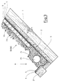
- roof board cladding 2 On roof beams 1 of a sloping roof surface element 35 or 36 of a pointed roof 30, a roof board cladding 2 is applied. It consists of individual roof boards 3 through grooves and tongues arranged one below the other on their outer sides are connected.
- roof board cladding 2 laid out. It consists of a non-woven layer 4, the is placed directly on the board cladding 2. Above the A non-woven film 4 extends through a root-resistant film 5 and over this a support layer 6 (see FIGS. 1 and 3).
- the support layer 6, as shown in FIGS. 12, 13 and 14, be designed differently.
- the overlay layer 6 is an upper nonwoven layer 61. It points towards the root-resistant one below it Film 5 has an essentially smooth non-woven surface 67. The its opposite surface is also smooth.
- the upper fleece layer 61 has the task of adding liquid to save.
- the top fleece layer is just like the bottom fleece layer 4 61 made of polyamide fibers for this purpose.
- the support layer 6 is designed as a storage mat 62, which consists of a polyurethane foam. Characteristic is that the root-resistant film 5 opposite Surface of the storage mat 62 knobs curved forward 64 with intervening nub recesses 65. The surface of the storage mat opposite this nubbed surface 62 is smooth. The polyurethane foam the storage mat 62 ensures that a targeted amount of Moisture depending on the thickness of the storage mat 62 is saved. Support the underlying knobs Storage mat 62 with respect to the root-resistant film 5, see above that superfluous or squeezed out liquid very specifically can flow over the root-proof film.
- the overlay 6 is a building protection mat 60 realized.
- the building protection mat 63 is used for pitched roof greening not building protection in the traditional sense, but also for the targeted steering and management of the Liquid used.
- Highlighting feature of the building protection mat are tunnel recesses on the underside 66, which are arranged at a distance from one another.
- the building protection mat 60 is made of polyethylene. The polyethylene is chopped and put together into a mat. Find use Polyethylene residues that are chopped accordingly.
- On the underside provided with the tunnel recesses 66 opposite smooth surface is a very thin one Fleece arranged.
- the building protection mat 63 When the building protection mat 63 is put on the substantially smooth sheet surface element 51 of root-resistant film 5, drainage channels are created through which Moisture, water and other liquids, targeted be dissipated.
- the root-resistant film 5 takes over Functions in a special water management system. Within the chopped foam components of the building protection mat 63 however, moisture can be stored and stored in a very targeted manner being held.
- the grid plate layer 25 consists of individual grass grid plates 10, 100 shown in Figs. 4 to 10. They have lateral contact surfaces 11, 11 ', 110, 110' on that with an adjacent lawn grid by means of Interlocking elements 12, 12 ', 13, 13' or 112, 112 'or 113, 113 '.
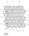
- the lawn grid plate 10 is shown in detail. It consists of honeycomb cells 14, by the side surfaces 11 and 11 'in dimensions 33 x 33 cm is limited. The individual cells have one Wall length of 35 mm and more and are about 36 mm high. At the upper edge of the cell walls 14 are designated by 18 Cutouts introduced. You can, like Figs. 7 and 8 show be semicircular. At the interface 11 'are at an angle of two side by side Walls 17 of the cells T-shaped hooking elements 12 '. The interlocking elements 12 'are in the first and arranged in the last cell angle. towards you are interlocking recesses 13 'which are at an acute angle the walls 17 of the last row of cells in the area of the contact surface 11 'are attached.
- the interlocking recess 13 'and the interlocking element 12 compatible therewith are shown in FIGS 7 and 8 can be seen in detail.
- the top T-bar of the Interlocking elements 12 ' has shoulders that compatible with the angle formed by the cells 14 in Area of the hooking recesses 13 'are.
- On the 11th designated contact surface are on the smooth walls 17th T-shaped interlocking elements 12 arranged. You lie in the walls 17 of the opposite row of cells in the area the contact surface 11 opposite hooking recesses 13.
- the interlocking elements 12 and the interlocking recesses 13 are compatible with each other.
- Each cell 14 of a turf grid 10 is closed with a bottom, in the middle there is a circular opening 16. This is from surrounded a bottom ring 19 which has a height H. The height H can be varied. Depending on requirements, the bottom ring 19 but also eliminated.
- FIG. 5 shows the lawn grid plate 100. It is also honeycomb-shaped formed and consists of cells 114, which by a bottom 115 are closed. Located in the middle there is a circular opening 116. Around the circular opening 116 are a plurality of additional openings spaced from one another 119 grouped. The cell walls 114 close at the top, 6 also shows, with a recess 118. This Recess 118 is angular and not as deep as the recess 18 of the lawn grid plate 10 is formed. On a contact surface 111 'hooking recesses 113 are formed. They correspond to the interlocking recesses 13 (cf. see also Fig. 7).
- the turf grid 100 differs from the turf grid 10 not only through the other training of water management and Steering systems formed by the openings 116 that Recesses 118 and the additional openings 119, but also by being twice as long, d. H. 64 cm like that Lawn grid plate 10 and is called Maxiplatte.
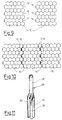
- FIG. 9 there are two grass pavers 10 in front of the Laying opposite. It is clear here that the interlocking elements 12 the hooking recesses 13 exactly opposite lie. The same applies to the interlocking elements 112 or the interlocking recess 113.
- Fig. 10 three grass grid panels 10 are connected to each other. It is clear that the interlocking elements 12 in the compatible interlocking recesses 13 engage. Here come the contact surfaces of the lawn grid plates 10th to lie next to each other and form a hook next to effective and very strong connection among themselves, which for the load on the grid plate layer of great importance are.
- a mat bolt 28 is shown. It exists from three clamp foot elements spaced apart at the same angle 31, 32, 33.
- the distance between the clamp foot elements 31, ... among themselves is so large that they prefer in the area of three converging walls 17 or 117 of three neighboring cells 114 (cf. also FIG. 6) are attachable.
- the distance between the clamp foot elements 31, ... can be designed so that it also serves as a connecting element can be used between two grass panels. Such a possibility is always an advantage if lawn grids are used that only touch each other set and not frictionally connected will.
- a plate anchoring element 40 shown. It consists of a strip-shaped one Surface element 41.
- the anchoring surface element 41 can a flexible plastic film, a flexible metal plate or the like.
- On the anchoring surface element 41 are spaced from each other anchor elements 42 in two Arranged rows. The distance between the anchor elements 42 next to each other is selected so that it fits into the openings 16 or 116 of cells 14 and 114, respectively, which are the last row of the grid plate layer Form 25, get hooked.
- FIG. 17 shows an eaves anchoring element 9.
- a continuous plate that serves as a platen element 91 and which is in a eaves element 94 ends.
- On the top plate element is in front of the eaves element 94 formed a trapezoidal support and drainage body 92 put on. In it are spaced apart and side by side drainage slots 93 are introduced.
- a drainage pipe 26 is arranged in this area, which is positioned in a gravel bed 20.
- Under the Gravel bed is the non-woven layer 4 and the root-resistant Foil 5 to the top of the eaves board 20 continued.
- the differently formed support layer 6, however is used as a boundary mat 24 between the gravel bed 20 and the vegetation layer 23 pulled up.
- 1, 2a, 2b, 3, 19 and 20 are different Embodiments for the form of formation of a vegetation layer 23, which is laid using the grid plate layer 25 will be shown.
- the first embodiment of a vegetation layer 23 is a greening mat 7, as shown in detail in FIG. 20 is. It consists of coconut fibers 44, in which with substrates and nutrients are brought in to the living Knock out plants 8.
- the advantage of the greening mat 7 is that a pre-greening is made regardless of the location can be. In addition, sowing does not need be carried out on site.
- the individual cells 14 and 114 as a growth substrate for extensive green roofs based on a roof substrate 43 filled with lava humus as a growth substance.
- Growth substrate can also include humus, rock wool, broken bricks and / or soil can be used.
- the special advantage this solution is that on the vegetation layer 23 existing green plants were given the opportunity through the coconut fibers 44 of the greening mat to root and anchor itself in the earth or humus layer, those in cells 14 and 114, respectively, of the lawn grid plates 10 or 110 is held. On the green plants and the Greening mat 7 and the underlying earth and humus layer Rain can occur in cells 14 or 114 be directed through cells 14 and 114, respectively. Depending on the place of use, the lawn grid plate 10 can or the lawn grid plate 110 can be selected. The cells 14 or 114 also ensure that the inclination of the Sloping roof surface element 35, 36 in the individual Cells 14, 114 can accumulate moisture. This moisture allows the green plants 8 to last longer Dryness from an existing moisture reservoir pull out the required liquid.
- the green plants 8 given the opportunity for them necessary nutrients from the layers below refer to.
- the lawn grid plates 10, 100 complete the greening mat in such a way that the green plants 8 on the sloping roof the growth and living conditions like those on the flat earth under natural conditions Will be provided. It is particularly advantageous that the humus in the cells or another growth substrate do not slip out due to the inclination can.
- FIG. 2a and 2b A second way of creating the vegetation layer 23 is shown in Figures 2a and 2b.
- Lawn grid mat 10 or 100 on the sloping roof surface element 35, 36 relocated.
- the liquid control and guidance system which passes through openings 16 and 116, the bottom ring 19 and the access openings 119 together is formed with the recesses 18 and 118, the supply the green plants 8 with the necessary water or the necessary nutrients.
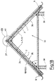
- the pointed roof 18 is due to the sloping roof elements already described 35, 36 formed.
- the sloping roof surface elements 35, 36 are inclined at an angle ⁇ with respect to the substructure. If possible, the angle ⁇ should not exceed 45 °. However, it should be noted at this point that cells 14 or 114 make it possible to realize an angle ⁇ can, which is over 45 °.
- the sloping roof surface elements 35, 36 formed by adjacent roof beams 1 with a roof board cladding 2 from roof boards 3 is constructed.
- Other materials like plastics, Metal or the like are for the construction of the sloping roof surface elements 35, 36 can be used.
- the roof beams 1 made of wooden beams Steel can step and special concrete ceilings and the like can be used.
- the top plate member 91 of the one in FIG eaves anchoring element 9 attached on the top surface of the sloping roof surface elements 35, 36, in this case the roof board cladding 2 with the applied nonwoven layer 4 and the root-resistant film 5, the top plate member 91 of the one in FIG eaves anchoring element 9 attached.
- the Attachment points e.g. Nail holes, with a Sealing material, e.g. Silicone, sealed. It can also an additional film or additionally or alone placed (welded).
- the eaves element 94 protrudes like a well-known gutter over the eaves area out.
- the overlay 6 becomes different Training as a top fleece layer 61, storage mat 62 or building protection mat 63 laid. After that the individual lawn grid plates 10 and 100, as already 9 and 10 explained, hooked together and the grid plate layer 25 is formed.
- the plate anchoring element 40 is designed to cover the entire area.
- the length of the two sloping roof surface elements 35, 36 is chosen from the eaves to the ridge 37 so long that the grass grid plates laid against one another correspond to their length.
- the openings 16 and 116 to be shown at the top in the bottoms 15 and 115 of the last lawn grid plate are plugged onto the anchoring elements designated by 42, as is shown particularly clearly in FIG. 19.
- the mat bolts designated 28 are installed spaced apart. For holding the coconut mat of the greening mat 7 it was found that about five pieces of mat bolts are to be inserted per m 2 .
- the greening mat 7 is laid out with the green plants 8.
- the individual retaining pin elements 29 drill in the process, 1 shows, in particular, in the mat made of coconut fibers 44 and hold the greening mat 7 non-positively firmly on the grid plate layer 25.
- the plate anchoring element 40 in Ridge 37 and through the two eaves anchoring elements 9 (see FIG. 18) the grid plate layers in the eaves area 25 are held.
- the Plate anchor member 40 prevents the entire Load of vegetation layer 23, which consists of the filled grid plate layers 25 and the greening mats on it 7 exists, only in the end point through the eaves anchoring element 9 must be kept. Rather, they are individual forces evenly distributed. Beyond pose the two grid plate layers 25 through each other hooked lawn grids 10 and 100 a stable load-bearing layer, which also the roof substructures Beam 1 and casing 2 relieved.
Landscapes
- Life Sciences & Earth Sciences (AREA)
- Environmental Sciences (AREA)
- Engineering & Computer Science (AREA)
- Architecture (AREA)
- Civil Engineering (AREA)
- Structural Engineering (AREA)
- Cultivation Of Plants (AREA)
- Inorganic Insulating Materials (AREA)
- Ceramic Products (AREA)
- Ceramic Capacitors (AREA)
Abstract
Description
- wenigstens einem Plattenelement, die auf dem Schrägdachelement angeordnet sind, und
- einer Vegetationsschicht, die auf die Plattenelemente aufgelegt wird.
- an einer durch wandparallele Wände der Zellen einer Zellenreihe ausgebildeten Berührungsfläche an wenigstens jeder zweiten Wand ein T-förmig ausgebildetes Verhakungselement mit einer in Richtung Zelle zeigender Schulter angeordnet ist, dem eine in der Wand in der gleichen Zellenreihe der gegenüberliegenden Berührungsfläche eingebrachte kompatible Verhakungsausnehmung gegenüberliegt, und
- an einer durch die schräg zueinander stehenden Wände einer Zellenreihe gebildeten Berührungsfläche in wenigstens jedem zweiten Einschlußwinkel eine Verhakungsausnehmung angebracht ist, der in zwischen zwei abgeschrägten Wänden einer Zellenreihe einer gegenüberliegenden Berührungsfläche gebildeten Winkel ein kompatibles T-förmig ausgebildetes Verhakungselement gegenüberliegt, an dessen Schulter Anschrägungen angeordnet sind.
Auf das Schrägdachelement kann eine Untervliesschicht gelegt werden. Auf diese Untervliesschicht kann eine Wurzelschicht angeordnet werden und auf diese wiederum eine Auflageschicht, auf der dann die Vegetationsschicht ruht. Die Untervliesschicht dient dazu, Feuchtigkeit von der Dachaußenhaut des Schrägdachelements fernzuhalten und abzuleiten. Damit wird ein Vermodern der Dachhaut verhindert. Die wurzelfeste Folie verhindert, daß die Wurzeln der Vegetationsschicht die Dachhaut aktiv angreifen und zersetzen. Die Auflageschicht hingegen sichert ein geregeltes Abführen überflüssiger Feuchtigkeit, die aus der Gitterplattenschicht heraustritt gezielt in eine Traufe oder ein ähnliches Wasserabführsystem abzuführen.
- eine Obervliesschicht,
- eine Speichermatte oder
- eine Bautenschutzmatte
- Fig. 1
- eine Teilansicht einer Schrägdachbegrünung,
- Fig. 2a und 2b
- Teildraufsichten einer Schrägdachbegrünung gemäß Fig. 1 in verschiedenen Aufbauphasen,
- Fig. 3
- einen vergrößerten Ausschnitt aus einer Schrägdachbegrünung gem. Fig. 1 und
- Fig. 4
- eine erste Ausführungsform einer Rasengitterplatte für eine Schrägdachbegrünung gemäß den Fig. 1 bis 3 in einer schematisch dargestellten Draufsicht,
- Fig. 5
- eine zweite Ausführungsform einer Rasengitterplatte für eine Schrägdachbegrünung gemäß den Fig. 1 bis 3 in einer schematisch dargestellten Draufsicht,
- Fig. 6
- einen Ausschnitt VI aus einer Rasengitterplatte gemäß Fig. 5,
- Fig. 7
- einen Schnitt durch eine Rasengitterplatte gemäß Fig. 4 entlang der Linie VII - VII,
- Fig. 8
- einen Schnitt durch eine Rasengitterplatte gemäß Fig. 5 entlang der Linie VIII - VIII,
- Fig. 9
- zwei Rasengitterplatten gemäß Fig. 4, 7 und 8 vor einer Verlegung in einer schematisch dargestellten Draufsicht,
- Fig. 10
- zwei Rasengitterplatten gemäß den Fig. 4, 7 und 8 im verlegten Zustand,
- Fig. 11
- einen Haltebolzen für eine Schrägdachbegrünung gemäß den Fig. 1 bis 3 in einer schematischen, perspektivischen Darstellung,
- Fig. 12
- eine erste Ausführungsform einer Mattenbeschichtung für eine Schrägdachbegrünung gemäß den Fig. 1 bis 3,
- Fig. 13
- eine zweite Ausführungsform einer Mattenbeschichtung für eine Schrägdachbegrünung gemäß den Fig. 1 bis 3,
- Fig. 14
- eine dritte Ausführungsform einer Mattenbeschichtung für eine Schrägdachbegrünung gemäß den Fig. 1 bis 3,
- Fig. 15
- ein Plattenverankerungselement für eine Halterung der Rasengitterplatten gemäß den Fig. 4 bis 10 für eine Schrägdachbegrünung gemäß den Fig. 1 bis 3,
- Fig. 16
- einen Schnitt durch ein Plattenverankerungselement gemäß Fig. 15 entlang der Linie XVI - XVI,
- Fig. 17
- eine weitere Ausführungsform eines Traufenverankerungselements für eine Schrägdachbegrünung gemäß den Fig. 1 bis 3,
- Fig. 18
- auf einem Spitzdach verlegte Rasengitterplatten gemäß den Fig. 4 bis 10 für eine Schrägdachbegrünung gemäß den Fig. 1 bis 3,
- Fig. 19
- einen Ausschnitt XIX aus einem Spitzdach gemäß Fig. 18 in einer vergrößerten Darstellung mit un- und begrünten Rasengitterplatten und
- Fig. 20
- eine Begrünungsmatte für eine Schrägdachbegrünung gemäß den Fig. 1 bis 3.
- 1
- Dachbalken
- 2
- Dachbretterverschalung
- 3
- Dachbretter
- 4
- Untervliesschicht
- 5
- wurzelfeste Folie
- 6
- Auflageschicht
- 7
- Begrünungsmatte
- 8
- Grünpflanzen
- 9
- Traufenverankerungselement
- 10
- Rasengitterplatte
- 11, 11'
- Berührungsfläche
- 12, 12'
- Verhakungselement
- 13, 13'
- Verhakungsausnehmung
- 14
- Zelle
- 15
- Boden
- 16
- Öffnung
- 17
- Wand
- 18
- Aussparung
- 19
- Bodenring
- 20
- Kiesbett
- 21
- Traufenbrett
- 22
- Dachsubstrat
- 23
- Vegetationsschicht
- 24
- Grenzmatte
- 25
- Gitterplattenschicht
- 26
- Drainagerohr
- 28
- Mattenbolzen
- 29
- Haltestiftelement
- 30
- Spitzdach
- 31, 32, 33
- Klammerfußelement
- 35, 36
- Schrägdachflächenelement
- 37
- First
- 38, 39
- Seitenwand
- 40
- Plattenverankerungselement
- 41
- Verankerungsflächenelement
- 42
- Ankerelement
- 43
- Dachsubstrat
- 44
- Kokosfasern
- 45
- Bewässerungsrohr
- 46
- Benetzungsflüssigkeit
- 47
- Flüssigkeitsausnehmung
- 51
- Folienflächenelement
- 61
- Obervliesschicht
- 62
- Speichermatte
- 63
- Bauschutzmatte
- 64
- Noppen
- 65
- Noppenausnehmung
- 66
- Tunnelausnehmung
- 67
- glatte Vliesfläche
- 91
- Aufsetzplattenelement
- 92
- Aufsetz- und Drainagekörper
- 93
- Drainageschlitz
- 94
- Traufenelement
- 100
- Rasengitterplatte
- 111, 111'
- Berührungsfläche
- 112, 112'
- Verhakungselement
- 113, 113'
- Verhakungsausnehmung
- 114
- Zelle
- 115
- Boden
- 116
- Öffnung
- 117
- Wand
- 118
- Aussparung
- 119
- Zusatzöffnung
- H
- Ringhohe
- α
- Dachneigungswinkel
Claims (21)
- Verfahren zur Herstellung einer Schrägdachbegrünung mit einer Vegetationsschicht (23), die auf Plattenelementen (10; 100), die auf einem Schrägdachflächenelement (35, 36) angeordnet sind, ausgelegt wird,
dadurch gekennzeichnet, daß als Plattenelemente zu einer Gitterplattenschicht (25) verlegbare Rasengitterplatten (10; 100) die eine Vielzahl von in einer Wabenstruktur angeordneten Zellen (14) aufweisen, die mit wenigstens einer Flüssigkeitsleitausnehmung (16, 18; 116, 118, 119) versehen sind, verwendet werden. - Einrichtung zur Begrünung von Schrägdächern, die wenigstens ein Schrägdachelement (35, 36) aufweisen, miteinem Plattenelement (10; 100), die auf dem Schrägdachelement (35, 36) angeordnet sind undeiner Vegetationsschicht (23), die auf den Plattenelementen (10; 100) angeordnet ist,
dadurch gekennzeichnet,daß auf dem Schrägdachelement (35, 36) eine Deckschicht (4, 5, 6) angeordnet ist,daß die Plattenelemente Rasengitterplatten (10; 100) sind,die aus einer Vielzahl von in einer Wabenstruktur angeordneten Zellen (14; 114) bestehen, die wenigstens eine Flüssigkeitsleitausnehmung (16, 18; 116, 118, 119) aufweisen unddie mit Verbindungs- und Halteelementen (9, 12, 12', 13, 13', 28, 40; 112, 112', 113, 113') über der Deckschicht (4, 5, 6) als eine Gitterplattenschicht (25) verlegt sind, unddaß mit der Gitterplattenschicht (25) die Vegetationsschicht (23) gehalten und erhaltbar ist. - Einrichtung nach Anspruch 2, dadurch gekennzeichnet, daß jede Rasengitterplatte (10; 100) derart mit Verbindungselementen versehen ist, daßan einer durch wandparallele Wände (17) der Zellen (14) einer Zellenreihe ausgebildeten Berührungsfläche (11; 111) an wenigstens jeder zweiten Wand (17; 117) ein T-förmig ausgebildetes Verhakungselement (12; 112) mit einer in Richtung Zelle (14; 114) zeigender Schulter angeordnet ist, dem eine in der Wand (17; 117) in der gleichen Zellenreihe der gegenüberliegenden Berührungsfläche (11; 111) eingebrachte kompatible Verhakungsausnehmung (13; 113) gegenüberliegt, undan einer durch die schräg zueinander stehenden Wände (17; 117) einer Zellenreihe gebildeten Berührungsfläche (11'; 111') in wenigstens jedem zweiten Einschlußwinkel eine Verhakungsausnehmung (13; 113) angebracht ist, der in zwischen zwei abgeschrägten Wänden (17; 117) einer Zellenreihe einer gegenüberliegenden Berührungsfläche (11'; 111') gebildeten Winkel ein kompatibles T-förmig ausgebildetes Verhakungselement (12'; 112') gegenüberliegt, an dessen Schulter Anschrägungen angeordnet sind.
- Einrichtung nach Anspruch 2 oder 3, dadurch gekennzeichnet, daß jede Zelle (14; 114) mit einem Boden (15; 115) verschlossen ist, der eine kreisrunde Öffnung (16; 116) als Flüssigkeitsleitausnehmung aufweist.
- Einrichtung nach einem der Ansprüche 2 bis 4, dadurch gekennzeichnet, daß der Boden (115) wenigstens einer Zelle (114) wenigstens eine Zusatzöffnung (119) als weitere Flüssigkeitsleitausnehmung aufweist, die um die kreisrunde Öffnung (116) beabstandet untereinander angeordnet sind.
- Einrichtung nach einem der Ansprüche 2 bis 5, dadurch gekennzeichnet, daß die kreisrunde Öffnung (16) mit einem Bodenring (19) mit einer Höhe (H) umgeben ist.
- Einrichtung nach einem der Ansprüche 2 bis 6, dadurch gekennzeichnet, daß die Zellenwände (14; 114) eine Länge von 35 mm oder größer haben.
- Einrichtung nach einem der Ansprüche 2 bis 7, dadurch gekennzeichnet, daß etwa mittig an jedem der oberen Ränder der Wände (14; 114) eine Aussparung (18; 118) als Flüssigkeitsausnehmung eingebracht ist.
- Einrichtung nach Anspruch 8, dadurch gekennzeichnet, daß die Aussparungen (18; 118) gerundet und/oder eckig ausgebildet sind.
- Einrichtung nach einem der Ansprüche 2 bis 9, dadurch gekennzeichnet, daß auf wenigstens eine Zellenwand (14; 114) wenigstens einer Rasengitterplatte (10; 110) der Gitterplattenschicht (25) wenigstens zwei Klammerfußelemente (31, 32, 33) eines Mattenbolzens (28) geschoben sind, mit dessen Haltestiftelement (29) als Halteelement die Vegetationsschicht (23) wenigstens teilweise gehalten ist.
- Einrichtung nach einem der Ansprüche 2 bis 10, dadurch gekennzeichnet, daß die Deckschicht ausbesteht.einer Untervliesschicht (4), die auf dem Schrägdachelement (35, 36) angeordnet ist,einer wurzelfesten Folie (5), die auf der Untervliesschicht (4) angeordnet ist, undeiner Auflageschicht (6), die auf der wurzelfesten Folie (5) angeordnet ist,
- Einrichtung nach Anspruch 11, dadurch gekennzeichnet, daß die Auflageschicht (6) alsausgebildet ist.eine Obervliesschicht (61), die eine wenigstens teilweise glatte Vliesoberfläche (67) aufweist,eine Speichermatte (62), die Noppen (64) und Noppenausnehmungen (65) aufweist, odereine Bautenschutzmatte (63), die wenigstens eine durchlaufende Tunnelausnehmung (66) aufweist,
- Einrichtung nach einem der Ansprüche 2 bis 12, dadurch gekennzeichnet, daß die Vegetationsschicht (23) eine Begrünungsmatte (7) aufweist, die mit einer Vegetation (8) auf der Gitterplattenschicht (25) aufzulegen ist.
- Einrichtung nach einem der Ansprüche 2 bis 13, dadurch gekennzeichnet, daß die Begrünungsmatte (7) aus Kokosfasern (44) besteht, in der Grünpflanzen (8) als Vegetation angeordnet sind.
- Einrichtung nach einem der Ansprüche 2 bis 14, dadurch gekennzeichnet, daß die Zellen (14; 114) der Rasengitterplatten (10; 100) mit einem Dachsubstrat (22) wenigstens teilweise verfüllt sind, in der die Grünpflanzen (8) wenigstens teilweise verwurzelbar sind.
- Einrichtung nach einem der Ansprüche 2 bis 15, dadurch gekennzeichnet, daß die Vegetationsschicht (23) aus vorgegrünten Rasengitterplatten (10; 100) besteht, deren Zellen (14; 114) mit dem Dachsubstrat (22) verfüllt und in der die Grünpflanzen (8) wenigstens teilweise vergegrünt angeordnet sind.
- Einrichtung nach einem der Ansprüche 2 bis 16, dadurch gekennzeichnet, daß die Gitterplattenschichten (23) zweier Schrägdachelemente (35, 36) im First (37) eines Daches (30) mit wenigstens einem Verankerungselement (40) als Verbindungselement verbunden sind.
- Einrichtung nach einem der Ansprüche 2 bis 17, dadurch gekennzeichnet, daß das Verankerungselement (40) ein Verankerungsflächenelement (41) aufweist, auf dem beabstandet untereinander Ankerelemente (42) angeordnet sind, die wenigstens teilweise durch die Öffnungen (16) in die Zellen (14) hineinragen.
- Einrichtung nach einem der Ansprüche 2 bis 18, dadurch gekennzeichnet, daß die Gitterplattenschicht (23) auf den Schrägdachelementen (35, 36) im Traufenbereich des Daches (30) durch ein Traufenverankerungselement (9) als Halteelement wenigstens teilweise gehalten ist.
- Einrichtung nach einem der Ansprüche 2 bis 19, dadurch gekennzeichnet, daß das Verankerungselement (9) ein Aufsatzplattenelement aufweist,daß unter den Untervlies (61) auf dem Schrägdachelement (35, 36) angeordnet ist,auf dem ein Abstütz- und Drainagekörper mit wenigstens einem Drainageschlitz (93) angeordnet ist unddaß mit einem Traufenelement (94) traufenseitig abschließt.
- Einrichtung nach einem der Ansprüche 2 bis 20, dadurch gekennzeichnet,daß die wurzelfeste Folie (5) ein Polyvinylchlorid-(PVC)- oder eine Polyethylen- (PE)-Folie ist,daß die Vliesschichten (4, 61) aus Polyamidfasern hergestellt sind,daß die Rasengitterplatten (10; 110) als Kunststoff-Spritzgußteile ausgebildet sind,daß die Speichermatte (62) aus Polyurethanschaum und die Bautenschutzmatte (63) aus Polyethylen hergestellt sind.
Applications Claiming Priority (2)
| Application Number | Priority Date | Filing Date | Title |
|---|---|---|---|
| DE29707887U | 1997-05-02 | ||
| DE29707887U DE29707887U1 (de) | 1997-05-02 | 1997-05-02 | Schrägdachbegrünung |
Publications (2)
| Publication Number | Publication Date |
|---|---|
| EP0875637A2 true EP0875637A2 (de) | 1998-11-04 |
| EP0875637A3 EP0875637A3 (de) | 1999-09-15 |
Family
ID=8039834
Family Applications (1)
| Application Number | Title | Priority Date | Filing Date |
|---|---|---|---|
| EP98107898A Withdrawn EP0875637A3 (de) | 1997-05-02 | 1998-04-30 | Schrägdachbegrünung |
Country Status (2)
| Country | Link |
|---|---|
| EP (1) | EP0875637A3 (de) |
| DE (1) | DE29707887U1 (de) |
Cited By (9)
| Publication number | Priority date | Publication date | Assignee | Title |
|---|---|---|---|---|
| DE19955753A1 (de) * | 1999-11-19 | 2001-06-21 | Harzmann Optima Marketing Und | Wasserleitprofil |
| DE10008021A1 (de) * | 2000-02-22 | 2001-08-23 | Gummiwerk Kraiburg Relastec Gm | Begrünbares Belagmaterial für horizontale Bauwerksflächen und Verfahren zu dessen Herstellung |
| WO2002012653A1 (en) * | 2000-08-09 | 2002-02-14 | Longlac Wood Industries Inc | Free floating sub-floor panel |
| FR2882076A1 (fr) * | 2005-02-16 | 2006-08-18 | Nidaplast Honeycombs Soc Par A | Revetement pour toiture plate ou inclinee de batiment |
| FR2924572A1 (fr) * | 2007-12-06 | 2009-06-12 | Thierry Jean Christophe Lefillastre | Recuperation, stockage, reutilisation de l'eau pluviale et vegetalisation de toutes surfaces |
| WO2009111995A1 (en) * | 2008-03-10 | 2009-09-17 | Benda Trade S.R.O. | Vegetation roof, especially pitched, and method of its production |
| WO2020018599A3 (en) * | 2018-07-16 | 2020-07-23 | Green Roof Specialty Products Llc | Frictional drainage layer in a green roof, paver, or solar assembly |
| US20210347988A1 (en) * | 2018-09-28 | 2021-11-11 | Dow Global Technologies Llc | Hydrophilic composite |
| US20220033564A1 (en) * | 2018-09-28 | 2022-02-03 | Dow Global Technologies Llc | Hydrophilic polyurethane foam for water retention applications |
Families Citing this family (1)
| Publication number | Priority date | Publication date | Assignee | Title |
|---|---|---|---|---|
| CZ301884B6 (cs) * | 2008-03-10 | 2010-07-21 | Benda Trade S.R.O. | Reklamní plocha vytvorená na svahu a/nebo mající svažitý povrch |
Citations (5)
| Publication number | Priority date | Publication date | Assignee | Title |
|---|---|---|---|---|
| DE3712867A1 (de) | 1987-04-15 | 1988-11-03 | Rieco Begruenungssysteme Gmbh | Wasserfangschale |
| EP0400158A1 (de) | 1989-05-12 | 1990-12-05 | Norbert Funke | Vorrichtung zur Befestigung von Rasenwegen |
| DE4004284C1 (en) | 1990-02-13 | 1991-08-01 | Wolfgang 2833 Gross Ippener De Behrens | Biomass for making roofs and artificial surfaces green - comprises dry pourable mixt. of adhesive powder as binder and seeds, plant parts and/or mosses and fertiliser |
| DE4413260A1 (de) | 1994-04-16 | 1995-11-02 | Wolfgang Behrens | Vegetationssubstrat sowie Vegetationssystem zur Begrünung |
| DE4416943A1 (de) | 1994-05-13 | 1995-12-07 | Funke Kunststoffe Gmbh | Aufbau einer Tragfläche für ein Betreten sich bewegender Pferde, insbesondere Reitplatzaufbau |
Family Cites Families (1)
| Publication number | Priority date | Publication date | Assignee | Title |
|---|---|---|---|---|
| DE9216295U1 (de) * | 1992-12-01 | 1993-01-28 | Zink, Walter, 7440 Nürtingen | Begrünbare Schrägdachdeckung |
-
1997
- 1997-05-02 DE DE29707887U patent/DE29707887U1/de not_active Expired - Lifetime
-
1998
- 1998-04-30 EP EP98107898A patent/EP0875637A3/de not_active Withdrawn
Patent Citations (5)
| Publication number | Priority date | Publication date | Assignee | Title |
|---|---|---|---|---|
| DE3712867A1 (de) | 1987-04-15 | 1988-11-03 | Rieco Begruenungssysteme Gmbh | Wasserfangschale |
| EP0400158A1 (de) | 1989-05-12 | 1990-12-05 | Norbert Funke | Vorrichtung zur Befestigung von Rasenwegen |
| DE4004284C1 (en) | 1990-02-13 | 1991-08-01 | Wolfgang 2833 Gross Ippener De Behrens | Biomass for making roofs and artificial surfaces green - comprises dry pourable mixt. of adhesive powder as binder and seeds, plant parts and/or mosses and fertiliser |
| DE4413260A1 (de) | 1994-04-16 | 1995-11-02 | Wolfgang Behrens | Vegetationssubstrat sowie Vegetationssystem zur Begrünung |
| DE4416943A1 (de) | 1994-05-13 | 1995-12-07 | Funke Kunststoffe Gmbh | Aufbau einer Tragfläche für ein Betreten sich bewegender Pferde, insbesondere Reitplatzaufbau |
Cited By (15)
| Publication number | Priority date | Publication date | Assignee | Title |
|---|---|---|---|---|
| DE19955753A1 (de) * | 1999-11-19 | 2001-06-21 | Harzmann Optima Marketing Und | Wasserleitprofil |
| DE19955753B4 (de) * | 1999-11-19 | 2004-02-12 | Harzmann-Optima Marketing- Und Vertriebs Gmbh | Wasserleitprofil |
| DE10008021A1 (de) * | 2000-02-22 | 2001-08-23 | Gummiwerk Kraiburg Relastec Gm | Begrünbares Belagmaterial für horizontale Bauwerksflächen und Verfahren zu dessen Herstellung |
| WO2002012653A1 (en) * | 2000-08-09 | 2002-02-14 | Longlac Wood Industries Inc | Free floating sub-floor panel |
| US6918215B2 (en) | 2000-08-09 | 2005-07-19 | Longlac Wood Industries Inc. | Free floating sub-floor panel |
| FR2882076A1 (fr) * | 2005-02-16 | 2006-08-18 | Nidaplast Honeycombs Soc Par A | Revetement pour toiture plate ou inclinee de batiment |
| FR2924572A1 (fr) * | 2007-12-06 | 2009-06-12 | Thierry Jean Christophe Lefillastre | Recuperation, stockage, reutilisation de l'eau pluviale et vegetalisation de toutes surfaces |
| WO2009111995A1 (en) * | 2008-03-10 | 2009-09-17 | Benda Trade S.R.O. | Vegetation roof, especially pitched, and method of its production |
| CZ301388B6 (cs) * | 2008-03-10 | 2010-02-10 | Benda Trade S.R.O. | Vegetacní strecha, zejména sklonitá a zpusob její výroby |
| DE212008000114U1 (de) | 2008-03-10 | 2010-12-09 | Benda Trade S.R.O. | Vegationsdach, insbesondere geneigtes Dach |
| WO2020018599A3 (en) * | 2018-07-16 | 2020-07-23 | Green Roof Specialty Products Llc | Frictional drainage layer in a green roof, paver, or solar assembly |
| US11805742B2 (en) | 2018-07-16 | 2023-11-07 | Green Roof Specialty Products, Llc | Frictional drainage layer in a green roof, paver, and/or solar assembly |
| US20210347988A1 (en) * | 2018-09-28 | 2021-11-11 | Dow Global Technologies Llc | Hydrophilic composite |
| US20220033564A1 (en) * | 2018-09-28 | 2022-02-03 | Dow Global Technologies Llc | Hydrophilic polyurethane foam for water retention applications |
| US11814466B2 (en) * | 2018-09-28 | 2023-11-14 | Dow Global Technologies Llc | Hydrophilic polyurethane foam for water |
Also Published As
| Publication number | Publication date |
|---|---|
| EP0875637A3 (de) | 1999-09-15 |
| DE29707887U1 (de) | 1998-09-03 |
Similar Documents
| Publication | Publication Date | Title |
|---|---|---|
| EP0045376B1 (de) | Schrägdachabdeckung | |
| DE20213320U1 (de) | Bepflanzungs- und Begrünungssystem für landschaftsgärtnerische und dekorative Zwecke | |
| DE3805069C2 (de) | ||
| DE60008033T2 (de) | Verfahren zur Flächebegrünung und Behälter mit Wasservorrat zur Verwendung in diesem Verfahren | |
| DE3200869C2 (de) | ||
| DE212008000114U1 (de) | Vegationsdach, insbesondere geneigtes Dach | |
| EP0939585A1 (de) | Bahnförmiger vegetationskörper | |
| EP1594356A1 (de) | Matte für vegetationskörper | |
| DE2438300C2 (de) | Fertigelementensatz für Dachgartenkulturen | |
| DE2248911A1 (de) | Flaechige bodenentwaesserung mit naturbewuchsmoeglichkeit | |
| EP2599916A2 (de) | Reit- oder Sportplatzboden und Verfahren zu seiner Herstellung | |
| DE29707887U1 (de) | Schrägdachbegrünung | |
| DE2253906A1 (de) | Gartenanlage | |
| DE19635480C2 (de) | Dach | |
| DE102010045283A1 (de) | Wasserverteileinrichtung für Dachbegrünungen | |
| EP0575940B1 (de) | Dachbegrünung für Flachdächer | |
| DE3529717A1 (de) | Begruenung von dachflaechen | |
| DE2755958A1 (de) | Gartenanlage | |
| DE202008000025U1 (de) | Begrünbare Außenhaut einer Böschung, bei der Teile der Außenhaut mit einer textilen Gewebe- oder Gewirkeschicht abgedeckt sind | |
| EP0202346B1 (de) | Fertigelement mit Vegetation | |
| EP0617172A2 (de) | Vegetative Lärmschutzwand | |
| EP0971576B1 (de) | Vegetationselement für die begrünung von mit vertiefungen und erhöhungen versehenen dächern | |
| DE19630830C2 (de) | Dachbegrünung und Verfahren zur Herstellung | |
| DE10008021A1 (de) | Begrünbares Belagmaterial für horizontale Bauwerksflächen und Verfahren zu dessen Herstellung | |
| DE3015147A1 (de) | Dachabdeckung |
Legal Events
| Date | Code | Title | Description |
|---|---|---|---|
| PUAI | Public reference made under article 153(3) epc to a published international application that has entered the european phase |
Free format text: ORIGINAL CODE: 0009012 |
|
| AK | Designated contracting states |
Kind code of ref document: A2 Designated state(s): AT BE CH DE DK FR GB LI NL |
|
| AX | Request for extension of the european patent |
Free format text: AL;LT;LV;MK;RO;SI |
|
| PUAL | Search report despatched |
Free format text: ORIGINAL CODE: 0009013 |
|
| AK | Designated contracting states |
Kind code of ref document: A3 Designated state(s): AT BE CH CY DE DK ES FI FR GB GR IE IT LI LU MC NL PT SE |
|
| AX | Request for extension of the european patent |
Free format text: AL;LT;LV;MK;RO;SI |
|
| 17P | Request for examination filed |
Effective date: 19991213 |
|
| AKX | Designation fees paid |
Free format text: AT BE CH DE DK FR GB LI NL |
|
| STAA | Information on the status of an ep patent application or granted ep patent |
Free format text: STATUS: THE APPLICATION IS DEEMED TO BE WITHDRAWN |
|
| 18D | Application deemed to be withdrawn |
Effective date: 20021031 |