EP0875659A2 - Ventil für Tiefbohrungen - Google Patents
Ventil für Tiefbohrungen Download PDFInfo
- Publication number
- EP0875659A2 EP0875659A2 EP19980303452 EP98303452A EP0875659A2 EP 0875659 A2 EP0875659 A2 EP 0875659A2 EP 19980303452 EP19980303452 EP 19980303452 EP 98303452 A EP98303452 A EP 98303452A EP 0875659 A2 EP0875659 A2 EP 0875659A2
- Authority
- EP
- European Patent Office
- Prior art keywords
- chamber
- fluid
- valve
- pressure
- housing
- Prior art date
- Legal status (The legal status is an assumption and is not a legal conclusion. Google has not performed a legal analysis and makes no representation as to the accuracy of the status listed.)
- Withdrawn
Links
- 239000012530 fluid Substances 0.000 claims abstract description 188
- 238000004891 communication Methods 0.000 claims abstract description 49
- 230000004044 response Effects 0.000 claims description 23
- 238000000034 method Methods 0.000 claims description 16
- 238000006073 displacement reaction Methods 0.000 claims description 9
- 239000002360 explosive Substances 0.000 claims description 9
- 230000002706 hydrostatic effect Effects 0.000 description 13
- 238000010304 firing Methods 0.000 description 6
- 230000004913 activation Effects 0.000 description 5
- 230000006835 compression Effects 0.000 description 4
- 238000007906 compression Methods 0.000 description 4
- 239000003999 initiator Substances 0.000 description 4
- 230000008901 benefit Effects 0.000 description 3
- 238000005259 measurement Methods 0.000 description 3
- 238000005474 detonation Methods 0.000 description 2
- 230000003116 impacting effect Effects 0.000 description 2
- 230000007246 mechanism Effects 0.000 description 2
- 230000001133 acceleration Effects 0.000 description 1
- 230000003213 activating effect Effects 0.000 description 1
- 238000007792 addition Methods 0.000 description 1
- 238000010276 construction Methods 0.000 description 1
- 230000001186 cumulative effect Effects 0.000 description 1
- 238000012217 deletion Methods 0.000 description 1
- 230000037430 deletion Effects 0.000 description 1
- 238000002955 isolation Methods 0.000 description 1
- 238000012986 modification Methods 0.000 description 1
- 230000004048 modification Effects 0.000 description 1
- 238000005086 pumping Methods 0.000 description 1
- 230000012923 response to hydrostatic pressure Effects 0.000 description 1
- 238000007789 sealing Methods 0.000 description 1
- 238000010008 shearing Methods 0.000 description 1
- 238000004513 sizing Methods 0.000 description 1
- 238000006467 substitution reaction Methods 0.000 description 1
Images




Classifications
-
- E—FIXED CONSTRUCTIONS
- E21—EARTH OR ROCK DRILLING; MINING
- E21B—EARTH OR ROCK DRILLING; OBTAINING OIL, GAS, WATER, SOLUBLE OR MELTABLE MATERIALS OR A SLURRY OF MINERALS FROM WELLS
- E21B43/00—Methods or apparatus for obtaining oil, gas, water, soluble or meltable materials or a slurry of minerals from wells
- E21B43/11—Perforators; Permeators
- E21B43/116—Gun or shaped-charge perforators
- E21B43/1185—Ignition systems
- E21B43/11852—Ignition systems hydraulically actuated
-
- E—FIXED CONSTRUCTIONS
- E21—EARTH OR ROCK DRILLING; MINING
- E21B—EARTH OR ROCK DRILLING; OBTAINING OIL, GAS, WATER, SOLUBLE OR MELTABLE MATERIALS OR A SLURRY OF MINERALS FROM WELLS
- E21B21/00—Methods or apparatus for flushing boreholes, e.g. by use of exhaust air from motor
- E21B21/10—Valve arrangements in drilling-fluid circulation systems
- E21B21/103—Down-hole by-pass valve arrangements, i.e. between the inside of the drill string and the annulus
-
- E—FIXED CONSTRUCTIONS
- E21—EARTH OR ROCK DRILLING; MINING
- E21B—EARTH OR ROCK DRILLING; OBTAINING OIL, GAS, WATER, SOLUBLE OR MELTABLE MATERIALS OR A SLURRY OF MINERALS FROM WELLS
- E21B23/00—Apparatus for displacing, setting, locking, releasing or removing tools, packers or the like in boreholes or wells
- E21B23/04—Apparatus for displacing, setting, locking, releasing or removing tools, packers or the like in boreholes or wells operated by fluid means, e.g. actuated by explosion
-
- E—FIXED CONSTRUCTIONS
- E21—EARTH OR ROCK DRILLING; MINING
- E21B—EARTH OR ROCK DRILLING; OBTAINING OIL, GAS, WATER, SOLUBLE OR MELTABLE MATERIALS OR A SLURRY OF MINERALS FROM WELLS
- E21B23/00—Apparatus for displacing, setting, locking, releasing or removing tools, packers or the like in boreholes or wells
- E21B23/04—Apparatus for displacing, setting, locking, releasing or removing tools, packers or the like in boreholes or wells operated by fluid means, e.g. actuated by explosion
- E21B23/042—Apparatus for displacing, setting, locking, releasing or removing tools, packers or the like in boreholes or wells operated by fluid means, e.g. actuated by explosion using a single piston or multiple mechanically interconnected pistons
-
- E—FIXED CONSTRUCTIONS
- E21—EARTH OR ROCK DRILLING; MINING
- E21B—EARTH OR ROCK DRILLING; OBTAINING OIL, GAS, WATER, SOLUBLE OR MELTABLE MATERIALS OR A SLURRY OF MINERALS FROM WELLS
- E21B34/00—Valve arrangements for boreholes or wells
- E21B34/06—Valve arrangements for boreholes or wells in wells
- E21B34/10—Valve arrangements for boreholes or wells in wells operated by control fluid supplied from outside the borehole
- E21B34/102—Valve arrangements for boreholes or wells in wells operated by control fluid supplied from outside the borehole with means for locking the closing element in open or closed position
- E21B34/103—Valve arrangements for boreholes or wells in wells operated by control fluid supplied from outside the borehole with means for locking the closing element in open or closed position with a shear pin
-
- Y—GENERAL TAGGING OF NEW TECHNOLOGICAL DEVELOPMENTS; GENERAL TAGGING OF CROSS-SECTIONAL TECHNOLOGIES SPANNING OVER SEVERAL SECTIONS OF THE IPC; TECHNICAL SUBJECTS COVERED BY FORMER USPC CROSS-REFERENCE ART COLLECTIONS [XRACs] AND DIGESTS
- Y10—TECHNICAL SUBJECTS COVERED BY FORMER USPC
- Y10T—TECHNICAL SUBJECTS COVERED BY FORMER US CLASSIFICATION
- Y10T137/00—Fluid handling
- Y10T137/1624—Destructible or deformable element controlled
- Y10T137/1632—Destructible element
- Y10T137/1669—Tensile or sheer pin or bolt
Definitions
- the present invention relates generally to operations performed in conjunction with a subterranean well and, in an embodiment described herein, more particularly provides a valve used to control actuation of a tool positioned within the well and associated methods. More specifically, the invention relates to a pressure activated switch valve.
- the activation mechanism causes power to be supplied to a control circuit when the hydrostatic pressure reaches a predetermined amount. Thereafter, as the tool is lowered in the well, a timer determines when the power will be supplied to a motor in order to set a lock or plug within the well at an appropriate location.
- An accelerometer may also be utilized to reset the timer as the tool is displaced in the well, so that the lock or plug is not inadvertently set before the tool has arrived at the appropriate location.
- the timer is set before the tool enters the well. This timer setting is based on an estimate of the time required to lower the tool to the appropriate location within the well. Unfortunately, this estimate may be incorrect, perhaps due to unforeseen difficulties in lowering the tool in the well, in which case it is likely that the lock or plug will be set prior to reaching the appropriate location. For example, an obstruction may be present in the wellbore or a portion of the wellbore may be deviated from vertical sufficiently far to impede lowering of the tool therein.
- the tubing will typically not accelerate or decelerate at a sufficient level required to excite the accelerometer, due to the mass of the tubing.
- a valve which is responsive to a fluid pressure differential controllable from the earth's surface, utilization of which does not require precise calculation of hydrostatic pressure within a well.
- the valve is suitable for use in conjunction with a tool conveyed into the well by tubing attached thereto. Methods of actuating the tool are also provided.
- a valve is provided by the present invention, which is operatively interconnectable to two pressure regions of a subterranean well.
- the pressure regions may correspond to the interior and exterior of the tubing.
- the valve includes a member that has two surface areas formed thereon. Each of the surface areas is in fluid communication with a corresponding one of the pressure regions. The member displaces when fluid pressure in one of the pressure regions is greater than fluid pressure in the other pressure region by a predetermined amount. Displacement of the member causes a chamber of the valve to be placed in fluid communication with one of the pressure regions.
- the chamber may have approximately atmospheric pressure therein when the member is in the first position.
- a piston may be in fluid communication with the chamber.
- a switch may be operated by displacement of the piston when the chamber is in fluid communication with the second pressure region.
- an explosive device may be detonated by displacement of the piston when the chamber is in fluid communication with the second pressure region.
- a shear device may be in engagement with the member, the shear device releasably securing the member in the first position until fluid pressure in the first region exceeds fluid pressure in the second region by the predetermined amount.
- a generally tubular sleeve may at least partially radially outwardly surround the member, the member being axially slidingly received within the sleeve.
- the sleeve may have first and second seal bores formed internally thereon, and the member may have first and second diameters formed externally thereon, the first diameter sealingly engaging the first seal bore and the second diameter sealingly engaging the second seal bore.
- the first and second surface areas may correspond to the area of the first seal bore.
- a valve which is operatively positionable within a subterranean well having a tubing string disposed therein.
- the valve includes a housing, first and second fluid passages. a chamber and a member displaceable relative to the housing.
- the housing is sealingly connectable to the tubing string, thereby placing the first fluid passage in fluid communication with the interior of the tubing string and placing the second fluid passage in fluid communication with an annulus formed between the tubing string and the wellbore.
- the member is displaceable, in response to a difference between fluid pressures in the first and second fluid passages, from one position in which the chamber is isolated from the second fluid passage to another position in which the chamber is in fluid communication with the second fluid passage.
- the member may be axially reciprocally disposed within the housing, and an end of the member may extend into the first fluid passage.
- the member may sealingly engage a seal bore at first and second axially spaced apart locations, and a third fluid passage may intersect the seal bore axially between the first and second locations.
- the third fluid passage may be in fluid communication with the chamber.
- the member may displace relative to the seal bore to thereby permit fluid communication between the third fluid passage and the second fluid passage when the member displaces from the first to the second position.
- a shear structure may releasably secure the member against displacement relative to the housing.
- the member may have a first piston area in fluid communication with the first fluid passage and a second piston area in fluid communication with the second fluid passage.
- the first piston area may be approximately equal in area to the second piston area.
- apparatus operatively positionable within a subterranean well, the apparatus comprising: a generally tubular housing; a member in fluid communication with the interior of the housing and with the exterior of the housing, the member being selectively displaceable in response to a difference in fluid pressure between the interior and the exterior of the housing; and a fluid passage adjacent the member, the fluid passage being selectively communicated with. and isolated from, one of the interior and exterior of the housing in response to displacement of the member.
- the member may be displaceable relative to the housing in response to a fluid pressure in the interior of the housing greater than a fluid pressure in the exterior of the housing by a predetermined amount.
- the member may have a piston area formed thereon, one side of the piston area being exposed to fluid pressure within the interior of the housing and an oppositely oriented side of the piston area being exposed to fluid pressure in the exterior of the housing.
- the member may have a generally rod shaped portion thereof, the rod shaped portion sealingly engaging a seal bore and straddling an intersection of the fluid passage with the seal bore.
- the fluid passage may have approximately atmospheric pressure therein when the fluid passage is isolated from the one of the interior and exterior of the housing.
- the fluid passage may be in fluid communication with the exterior of the housing when the member displaces relative to the housing.
- the apparatus may further comprise a piston exposed to fluid pressure within the fluid passage.
- apparatus which is operative positionable within a subterranean wellbore.
- the apparatus includes a switch disposed within a first chamber and a piston reciprocally disposed between the first chamber and another, second, chamber.
- the piston is displaceable to engage the switch in response to a difference in pressure between the two chambers.
- a valve is interconnected to the second chamber. The valve opens to place the second chamber in fluid communication with fluid pressure within the well.
- the switch may be an explosive device, in which case the piston causes detonation of the explosive device in response to a difference in pressure between the chambers.
- the first and second chambers may have approximately atmospheric pressure therein when the valve is in the first position.
- the valve may be selectively positionable in response to fluid pressure within the well.
- the valve may be further selectively positionable in response to a difference in fluid pressure within the well.
- the valve may be further selectively positionable in response to a predetermined difference in fluid pressure within the well.
- the second chamber may be in fluid communication with an exterior of the valve when the valve is in the second position.
- the valve may include a member axially slidingly and sealingly disposed at least partially within a generally tubular housing.
- the second chamber may be at least partially disposed within the housing.
- the apparatus may further comprise a generally tubular sleeve disposed at least partially radially between the member and the housing.
- a continuous fluid passage is formed from the exterior of the housing, inwardly through a first sidewall portion of the sleeve, axially within the member, outwardly through a second sidewall portion of the sleeve and to the second chamber when the valve is in the second position.
- a method for communicating pressure to a chamber, which method may be utilized to actuate a tool.
- a valve is interconnected with a tubing string to which the chamber is also connected.
- the valve is placed in fluid communication with the interior and exterior of the tubing string, and with the chamber. Fluid pressure is applied to the interior of the tubing string to create a predetermined differential pressure from the interior to the exterior of the tubing string.
- the valve is then opened in response to the predetermined differential pressure, thereby communicating fluid pressure to the chamber.
- a piston When used to actuate the tool, a piston may be displaced in response to the fluid pressure entering the chamber, thereby causing the piston to engage a structure positioned in another chamber within the tool.
- the opening step may further comprise placing the chamber in fluid communication with the interior of the tubing string.
- the opening step may further comprise shearing a shear member releasably securing the valve in a closed position.
- the method according to the invention may further comprise the step of permitting fluid communication between the interior and exterior of the tubing string before the applying step.
- the method according to the invention may further comprise the step of preventing fluid communication between the interior and exterior of the tubing string after the applying step.
- the preventing step may be performed in response to the applying step.
- the method according to the invention may further comprise the steps of releasing the predetermined differential fluid pressure and permitting fluid communication between the interior and exterior of the tubing string in response to the releasing step.
- the structure is a switch, and the switch is engaged with the piston by opening the valve.
- the structure is an explosive device, and the switch is engaged with the piston by opening the valve.
- the valve is opened by impacting a portion of the valve with a weight to thereby displace the portion of the valve and permit fluid communication between the second chamber and the one of the first and second fluid pressure sources.
- the present invention permits operations to be performed in subterranean wells with greater precision, economy and efficiency.
- Fig. 1 is a tool 10 similar to that described in U.S. Patent No. 5.492,173. Specifically, Fig. 1 shows various devices used to control activation of a motor 12 within the tool 10. In general, the devices are interposed between a power source 14 and the motor 12, in order to control when the motor will be activated. In the tool described in US Patent No. 5.492.173, activation of the motor 12 is utilized to set a plug or lock (not shown) at a particular desired location within a subterranean well.
- a piston 16 is axially reciprocally and sealingly disposed within a cylinder 18 of the tool 10.
- An upper volume 20 within the cylinder 18 above the piston 16 is exposed to hydrostatic pressure within the well.
- fluid pressure in the upper volume 20 gradually increases.
- a lower volume 22 within the cylinder 18 below the piston 16 contains atmospheric pressure.
- a compression spring 24 is disposed within the lower volume 22 and exerts an upwardly biasing force on the piston 16. Therefore, the hydrostatic pressure in the upper volume 20 must exceed a combination of atmospheric pressure and the biasing force of the spring 24 in order to downwardly displace the piston 16 relative to the cylinder 18.
- a switch 26 Operatively interconnected to the piston 16, and also disposed within atmospheric pressure, is a switch 26.
- the position of the switch 26 determines whether power is supplied from the power source 14 to a control circuit 28.
- the switch 26 is closed when the piston 16 displaces downwardly relative to the cylinder 18, and the switch is opened when the piston 16 is displaced upwardly relative to the cylinder by the spring 24. It will be readily appreciated by one of ordinary skill in the art that a predetermined hydrostatic pressure must be present in the volume 20 for the switch 26 to be closed. and for power to be supplied to the control circuit 28.
- the control circuit 28 includes a timer 30 and an accelerometer 32.
- the timer 30 is of the type which counts down from a set time period. at which time the timer conducts and supplies power to the motor 12.
- the time period may be set based upon an estimate, for example, of the time required to properly position the tool 10 within the well. This time period must be set before the tool 10 enters the well.
- the accelerometer 32 may be utilized to periodically reset the timer 30 whenever the tool accelerates or decelerates (e.g., as the tool is being lowered in the well).
- the time period for which the timer 30 is set corresponds to the amount of time after the tool 10 has stopped (no longer accelerates or decelerates), at which it is desired to set the plug or lock in the well.
- the tool 10 may be conveniently stopped periodically during its descent into the well by merely applying a brake on the wireline or slickline reel, to thereby ensure that the accelerometer 32 resets the timer 30, so that the plug or lock is not set prematurely.
- the mass of the tubing may prevent sufficient acceleration or deceleration needed to reset the timer 30, and the tubing may not be so easily or conveniently stopped periodically.
- the upper volume 20 is open to a wellbore 34 of the well surrounding the cylinder 18.
- This wellbore 34 is the source of the hydrostatic pressure used to displace the piston 16.
- the wellbore 34 is also the only pressure region available for displacing the piston 16.
- the fluid pressure in the wellbore 34 may be altered at the earth's surface by. for example, pumping into the wellbore to increase the pressure therein, but it will be readily appreciated that any such added pressure is cumulative to the hydrostatic pressure, and so any inaccuracies in calculating the hydrostatic pressure are not removed or changed by adding pressure thereto.
- fluid pressure in the wellbore 34 may be altered from the earth's surface, it cannot be more accurately controlled than the hydrostatic pressure.
- apparatus 40 is representatively illustrated which embodies principles of the present invention.
- directional terms such as “above”, “below”, “upper”, “lower”, etc., are used for convenience in referring to the accompanying drawings. Additionally, it is to be understood that the various embodiments of the present invention described herein may be utilized in various orientations, such as inclined, inverted, horizontal, vertical, etc., without departing from the principles of the present invention.
- the apparatus 40 is conveyed into a wellbore 42 by tubing, such as coiled tubing 44, extending to the earth's surface.
- tubing such as coiled tubing 44
- other forms of conveyance may be utilized without departing from the principles of the present invention.
- two pressure regions are available for use in operating the apparatus, namely, the interior 46 of the tubing 44, and the annulus 48 radially between the apparatus and the wellbore 42.
- the apparatus 40 is sealingly attached to the tubing 44, such that the tubing interior 46 is in fluid communication with an internal fluid passage 50 extending axially within the apparatus.
- the fluid passage 50 is pressure equalized with the annulus 48.
- This pressure equalization is provided by a pair of orifices 52 formed radially through a shuttle 54 of a conventional circulating valve 56.
- a suitable circulating valve is Halliburton part no. 698.10150
- a suitable flow diverter valve is Halliburton part no. 698.19035, both of which are manufactured by, and available from, Halliburton Company of Duncan, Oklahoma.
- a valve 60 is sealingly attached to the circulating valve 56 and is in fluid communication with the fluid passage 50. Attached below the valve 60 is a tool 62, which is similar in many respects to the tool 10 previously described. Specifically, in one respect, the tool 62 includes a piston 64 which may be displaced to engage a structure within the tool, in order to activate the tool. The valve 60 is utilized to control fluid communication with a chamber 66 to which the piston 64 is exposed, in order to control activation of the tool 62.
- the valve 60 is in fluid communication with the interior 46 of the tubing 44, and with the annulus 48.
- the valve 60 opens to permit fluid communication with the chamber 66 when a predetermined pressure differential exists between the interior 46 and the annulus 48. It will be readily appreciated that this pressure differential is easily and accurately controllable from the earth's surface at any time. It will also be readily appreciated that this method of activating the tool 62 does not require reliance on any estimates of time, or on movements of the tool and its means of conveyance. Additionally, this method permits an operator to remove the tool 62 from the well without any danger that it will be activated as it is being retrieved.
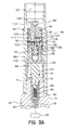
- FIG. 3A the apparatus 40 is representatively illustrated separated from the circulating valve 56 and tubing 44 for illustrative clarity.
- FIG. 3A is also somewhat enlarged as compared to FIG. 2, so that details of the valve 60 and tool 62 may be more clearly shown and described.
- the piston 64 is axially upwardly biased by a compression spring 68.
- An axially spaced apart set of circumferential seals 70, 72 are carried externally on the piston 64.
- the lower seal 72 is sealingly received in a central axial seal bore 74 formed in a top sub 76 of the tool 62.
- the seal 72 isolates the chamber 66 from an atmospheric chamber 78 within the tool 62.
- both of the chambers 66, 78 are at atmospheric pressure, and the piston 64 is upwardly biased by the spring 68 into contact with a sleeve 80 of the valve 60.
- the valve 60 is opened, the upper chamber 66 will be placed in fluid communication with the annulus 48, thereby causing axially downward displacement of the piston 64, provided sufficient fluid pressure exists in the annulus to compress the spring 68.
- a generally tubular spring retainer 82 Attached to the piston 64. and extending downwardly therefrom, is a generally tubular spring retainer 82.
- the spring retainer 82 radially outwardly surrounds a compression spring 84, which exerts an axially downwardly biasing force on a generally rod shaped plunger 86.
- An external shoulder formed on the plunger 86 engages an internal shoulder formed on the spring retainer 82 to prevent removal of the plunger from within the spring retainer.
- the tool 10 shown in FIG. 1 and generally described above may be used for the tool 62 shown in FIG. 3A.
- the piston 64 may correspond to the piston 16
- the spring 68 may correspond to the spring 24
- the chamber 66 may correspond to the chamber 20
- the chamber 78 may correspond to the chamber 22
- the switch 88 may correspond to the switch 26, etc.
- the piston 64 may engage the switch 88 (via the plunger 86) to close it and supply power to the control circuit 28.
- the switch 88 since opening of the valve 60 may be accurately controlled from the earth's surface, as will be described more fully hereinbelow, the switch 88 may be interconnected directly between the power source 14 and the motor 12, so that the motor is powered immediately upon opening of the valve.
- the valve 60 is maintained in its closed configuration as shown in FIG. 3A by a shear pin 90 installed radially through a sidewall portion of the sleeve 80 and a member 92 axially reciprocably and sealingly disposed within the sleeve.
- the member 92 prevents fluid communication between the annulus 48 and the chamber 66, and the valve 60 is closed.
- the member 92 is displaced to its downwardly disposed position relative to the sleeve 80 (see FIG. 3B), such fluid communication is permitted, and the valve 60 is open.
- the member 92 carries three axially spaced apart circumferential seals 94, 96, 98 externally thereon.
- the upper seal 94 is sealingly received in an upper bore 100 formed internally on the sleeve 80.
- the lower seals 96, 98 are sealingly received in a lower bore 102 formed internally on the sleeve 80, with the seals axially straddling a fluid passage 104 formed radially through the sleeve.
- the fluid passage 104 is in fluid communication with the chamber 66 via an opening 106 formed through the sleeve 80 below the bore 102. However, the fluid passage 104 is isolated from fluid communication with the annulus 48 by the seals 96, 98, and by a circumferential seal 108 carried externally on the sleeve 80.
- the seal 108 sealingly engages a bore 110 formed internally on a generally tubular housing 112 radially outwardly surrounding the sleeve 80.
- the housing 112 is configured for sealing attachment to the tubing 44 or circulating valve 56.
- the seal 108 and another circumferential seal 114 carried externally on the sleeve 80 axially straddle a fluid passage 116 formed radially through the housing 112.
- the fluid passage 116 is in fluid communication with one or more circumferentially spaced apart fluid passages 118 (only one of which is visible in FIG. 3A) formed radially through the sleeve 80, a series of circumferentially spaced apart fluid passages 120 formed radially through the member 92, an axially extending fluid passage 122 formed in the member and axially spaced apart fluid passages 124, 126 formed radially through the member.
- the member 92 will be downwardly biased by the difference between the fluid pressure in the fluid passage 50 and the fluid pressure in the annulus 48.
- the downwardly biasing force on the member 92 produced by the differential pressure between the fluid passage 50 and the annulus 48 will eventually shear the shear pin 90 and permit the member to downwardly displace relative to the sleeve 80.
- the operator may select the differential pressure at which the shear pin 90 shears.
- shear pin 90 shear when the fluid pressure in the fluid passage 50 exceeds the fluid pressure in the annulus 48 by approximately 600 psi, but it is to be understood that any predetermined differential pressure may be used without departing from the principles of the present invention.
- an upper end 128 of the member 92 extends axially outward from the sleeve 80.
- the end 128 is exposed to, and extends somewhat into, the fluid passage 50.
- a weighted bar or other object may be dropped through the interior 46 of the tubing 44 from the earth's surface to impact the end 128 and shear the shear pin 90, as an alternate method of downwardly displacing the member 92 and opening the valve 60. It is, thus, a distinct advantage of the apparatus 40 that it may activated using no less than two independent methods, each of which is predictably, controllably and conveniently performed from the earth's surface.
- the apparatus 40 is representatively illustrated with the valve 60 open and the tool 62 activated thereby.
- the member 92 is in its downwardly disposed position relative to the sleeve 80, so that the seals 96, 98 no longer axially straddle the fluid passage 104. Consequently, the fluid passage 104 is now in fluid communication with the annulus 48 via the fluid passages 126, 122, 124, 118 and 116.
- Fluid pressure in the annulus 48 has entered the chamber 66 and caused axially downward displacement of the piston 64.
- the upper seal 70 now sealingly engages an inclined shoulder 130 internally formed on the top sub 76, preventing further downward displacement of the piston 64.
- the plunger 86 has downwardly displaced with the piston 64 and has engaged the switch 88.
- the shear pin 90 is sheared, a predetermined differential pressure between the fluid passage 50 and the annulus 48 having been achieved.
- the shear pin 90 may have been sheared by applying sufficient force to the end 128 of the member 92 by, for example, impacting it with a weighted object.
- fluid pressures within the well may be placed in fluid communication with the chamber 66 without departing from the principles of the present invention.
- the fluid passage 104 may be appropriately positioned so that fluid communication with the fluid passage 50 is permitted when the member 92 is displaced to open the valve 60.
- the tool 62 may be activated with fluid pressure in the interior 46 of the tubing 44, instead of fluid pressure in the annulus 48.
- alternative differential pressures may be utilized to open the valve 60.
- fluid pressure in the annulus 48 greater than fluid pressure in the fluid passage 50 may be utilized to open the valve 60 by appropriate reconfiguration of the various seals and fluid passages therein.
- the tool 62 includes an explosive device, such as an initiator 132 and detonating cord 134, in the atmospheric chamber 78.
- the initiator 132 and detonating cord 134 may be of the type commonly used in firing heads for perforating guns, tubing cutters, setting tools, etc.
- the tool 62 as shown in FIG. 4 may be a firing head or other tool in which it is desired to activate or detonate an explosive device. It will, therefore, be readily appreciated that the apparatus 40, and the valve 60 apart therefrom, may be used for a variety of applications, other than those specifically described herein, without departing from the principles of the present invention.
- the plunger 86 has a generally conical shaped end 136 for engagement with the initiator 132, the plunger operating as a firing pin as shown in FIG. 4. Since it is at times preferable for a firing pin to engage an explosive device with maximum impact to ensure detonation thereof, the tool 62 may be provided without the spring retainer 82, spring 84 and plunger 86, the end 136 instead being formed on a downwardly extending portion of the piston 64. In that manner, the piston 64 would impact the initiator 132 directly.
- the valve 60 has been downwardly displaced relative to the housing 112 by a weighted bar 138.
- the bar 138 has been dropped from the earth's surface, through the interior 46 of the tubing 44, into the fluid passage 50 and into contact with the upper end 128 of the member 92. This contact (or impact) has sheared the shear pin 90 and permitted the member 92 to displace downwardly. Thus, it is not necessary to achieve a differential pressure between the two pressure regions. the fluid passage 50 and the annulus 48, for operation of the valve 60 according to the principles of the present invention.
- valve 60 the overall apparatus 40 and the methods described herein. It will be appreciated that the invention may be modified within the scope of the appended claims.
Landscapes
- Engineering & Computer Science (AREA)
- Life Sciences & Earth Sciences (AREA)
- Geology (AREA)
- Mining & Mineral Resources (AREA)
- Physics & Mathematics (AREA)
- Environmental & Geological Engineering (AREA)
- Fluid Mechanics (AREA)
- General Life Sciences & Earth Sciences (AREA)
- Geochemistry & Mineralogy (AREA)
- Mechanical Engineering (AREA)
- Earth Drilling (AREA)
- Temperature-Responsive Valves (AREA)
Applications Claiming Priority (2)
| Application Number | Priority Date | Filing Date | Title |
|---|---|---|---|
| US846866 | 1997-05-01 | ||
| US08/846,866 US6035880A (en) | 1997-05-01 | 1997-05-01 | Pressure activated switch valve |
Publications (2)
| Publication Number | Publication Date |
|---|---|
| EP0875659A2 true EP0875659A2 (de) | 1998-11-04 |
| EP0875659A3 EP0875659A3 (de) | 1999-06-02 |
Family
ID=25299165
Family Applications (1)
| Application Number | Title | Priority Date | Filing Date |
|---|---|---|---|
| EP19980303452 Withdrawn EP0875659A3 (de) | 1997-05-01 | 1998-05-01 | Ventil für Tiefbohrungen |
Country Status (5)
| Country | Link |
|---|---|
| US (1) | US6035880A (de) |
| EP (1) | EP0875659A3 (de) |
| AU (1) | AU721013B2 (de) |
| CA (1) | CA2236457A1 (de) |
| NO (1) | NO981913L (de) |
Cited By (4)
| Publication number | Priority date | Publication date | Assignee | Title |
|---|---|---|---|---|
| WO1999063198A1 (en) * | 1998-06-03 | 1999-12-09 | Schlumberger Technology Corporation | Mechanical shut-off valve |
| EP0931906A3 (de) * | 1998-01-20 | 2002-11-13 | Halliburton Energy Services, Inc. | Vorrichtung und Verfahren zur Betätigung eines Bohrlochwerkzeuges |
| WO2009002181A1 (en) * | 2007-06-22 | 2008-12-31 | Aker Well Service As | Arrangement and method for separation of tool string |
| US10217583B2 (en) | 2014-10-24 | 2019-02-26 | Halliburton Energy Services, Inc. | Pressure responsive switch for actuating a device |
Families Citing this family (18)
| Publication number | Priority date | Publication date | Assignee | Title |
|---|---|---|---|---|
| US8581740B2 (en) * | 2007-03-06 | 2013-11-12 | Schlumberger Technology Corporation | Method and apparatus for communicating signals to an instrument in a wellbore |
| WO2009085732A2 (en) | 2007-12-19 | 2009-07-09 | Halliburton Energy Services, Inc. | Mechanical actuator with electronic adjustment |
| US7902469B2 (en) * | 2008-08-28 | 2011-03-08 | Brian Wayne Hurst | Perforation gun pressure-actuated electrical switches and methods of use |
| US8915298B2 (en) * | 2010-06-07 | 2014-12-23 | Baker Hughes Incorporated | Slickline or wireline run hydraulic motor driven mill |
| US8579026B2 (en) | 2010-08-24 | 2013-11-12 | Halliburton Energy Services, Inc. | Safety structure for downhole power unit testing |
| US9540913B2 (en) * | 2012-04-11 | 2017-01-10 | Halliburton Energy Services, Inc. | Method and apparatus for actuating a differential pressure firing head |
| US9388665B2 (en) * | 2012-06-12 | 2016-07-12 | Schlumberger Technology Corporation | Underbalance actuators and methods |
| CA2914908C (en) | 2013-07-25 | 2017-01-17 | Halliburton Energy Services, Inc. | Wellbore isolation devices and methods of use to prevent pump offs |
| US9534484B2 (en) | 2013-11-14 | 2017-01-03 | Baker Hughes Incorporated | Fracturing sequential operation method using signal responsive ported subs and packers |
| US9816350B2 (en) | 2014-05-05 | 2017-11-14 | Baker Hughes, A Ge Company, Llc | Delayed opening pressure actuated ported sub for subterranean use |
| US9644450B2 (en) | 2015-01-26 | 2017-05-09 | Halliburton Energy Services, Inc. | Well flow control assemblies and associated methods |
| US9752421B2 (en) * | 2015-01-28 | 2017-09-05 | Owen Oil Tools Lp | Pressure switch for selective firing of perforating guns |
| WO2017209759A1 (en) | 2016-06-03 | 2017-12-07 | Halliburton Energy Services, Inc. | Shuttle valve assembly for gas compression and injection system |
| CA3020009C (en) * | 2018-05-21 | 2020-03-10 | Owen Oil Tools Lp | Signal transfer system for activating downhole tools and related methods |
| CN108729889B (zh) * | 2018-07-16 | 2024-04-02 | 物华能源科技有限公司 | 精准全方位控制无线级联通讯枪间测控装置 |
| US11174713B2 (en) | 2018-12-05 | 2021-11-16 | DynaEnergetics Europe GmbH | Firing head and method of utilizing a firing head |
| US11965393B2 (en) * | 2021-05-11 | 2024-04-23 | G&H Diversified Manufacturing Lp | Downhole setting assembly with switch module |
| US12392216B2 (en) * | 2021-05-11 | 2025-08-19 | G&H Diversified Manufacturing Lp | Initiator system providing set confirmation from plug setting tool in downhole well |
Citations (1)
| Publication number | Priority date | Publication date | Assignee | Title |
|---|---|---|---|---|
| US5492173A (en) | 1993-03-10 | 1996-02-20 | Halliburton Company | Plug or lock for use in oil field tubular members and an operating system therefor |
Family Cites Families (16)
| Publication number | Priority date | Publication date | Assignee | Title |
|---|---|---|---|---|
| US3796261A (en) * | 1972-09-11 | 1974-03-12 | Schlumberger Technology Corp | Releasable connection for pressure controlled test valve system |
| US3800705A (en) * | 1973-03-30 | 1974-04-02 | J Tamplen | Pressure balanced percussion firing system |
| US4306628A (en) * | 1980-02-19 | 1981-12-22 | Otis Engineering Corporation | Safety switch for well tools |
| US4709760A (en) * | 1981-10-23 | 1987-12-01 | Crist Wilmer W | Cementing tool |
| US4544034A (en) * | 1983-03-31 | 1985-10-01 | Geo Vann, Inc. | Actuation of a gun firing head |
| US4690227A (en) * | 1983-03-31 | 1987-09-01 | Halliburton Company | Gun firing head |
| GB2138925B (en) * | 1983-03-31 | 1988-02-24 | Vann Inc Geo | Firing of well perforation guns |
| US4650010A (en) * | 1984-11-27 | 1987-03-17 | Halliburton Company | Borehole devices actuated by fluid pressure |
| US4862964A (en) * | 1987-04-20 | 1989-09-05 | Halliburton Company | Method and apparatus for perforating well bores using differential pressure |
| US4817718A (en) * | 1987-09-08 | 1989-04-04 | Baker Oil Tools, Inc. | Hydraulically activated firing head for well perforating guns |
| US4911251A (en) * | 1987-12-03 | 1990-03-27 | Halliburton Company | Method and apparatus for actuating a tubing conveyed perforating gun |
| US4917189A (en) * | 1988-01-25 | 1990-04-17 | Halliburton Company | Method and apparatus for perforating a well |
| US5215148A (en) * | 1991-05-10 | 1993-06-01 | Dresser Industries, Inc. | Subsurface well pressure actuated and fired apparatus |
| US5176220A (en) * | 1991-10-25 | 1993-01-05 | Ava International, Inc. | Subsurface tubing safety valve |
| GB2272774B (en) * | 1992-11-13 | 1996-06-19 | Clive French | Completion test tool |
| US5603384A (en) * | 1995-10-11 | 1997-02-18 | Western Atlas International, Inc. | Universal perforating gun firing head |
-
1997
- 1997-05-01 US US08/846,866 patent/US6035880A/en not_active Expired - Lifetime
-
1998
- 1998-04-28 AU AU63683/98A patent/AU721013B2/en not_active Ceased
- 1998-04-28 NO NO981913A patent/NO981913L/no not_active Application Discontinuation
- 1998-04-30 CA CA002236457A patent/CA2236457A1/en not_active Abandoned
- 1998-05-01 EP EP19980303452 patent/EP0875659A3/de not_active Withdrawn
Patent Citations (1)
| Publication number | Priority date | Publication date | Assignee | Title |
|---|---|---|---|---|
| US5492173A (en) | 1993-03-10 | 1996-02-20 | Halliburton Company | Plug or lock for use in oil field tubular members and an operating system therefor |
Cited By (7)
| Publication number | Priority date | Publication date | Assignee | Title |
|---|---|---|---|---|
| EP0931906A3 (de) * | 1998-01-20 | 2002-11-13 | Halliburton Energy Services, Inc. | Vorrichtung und Verfahren zur Betätigung eines Bohrlochwerkzeuges |
| WO1999063198A1 (en) * | 1998-06-03 | 1999-12-09 | Schlumberger Technology Corporation | Mechanical shut-off valve |
| US6085843A (en) * | 1998-06-03 | 2000-07-11 | Schlumberger Technology Corporation | Mechanical shut-off valve |
| GB2354786A (en) * | 1998-06-03 | 2001-04-04 | Schlumberger Technology Corp | Mechanicle shut-off valve |
| GB2354786B (en) * | 1998-06-03 | 2002-05-22 | Schlumberger Technology Corp | Mechanical shut-off valve |
| WO2009002181A1 (en) * | 2007-06-22 | 2008-12-31 | Aker Well Service As | Arrangement and method for separation of tool string |
| US10217583B2 (en) | 2014-10-24 | 2019-02-26 | Halliburton Energy Services, Inc. | Pressure responsive switch for actuating a device |
Also Published As
| Publication number | Publication date |
|---|---|
| NO981913D0 (no) | 1998-04-28 |
| CA2236457A1 (en) | 1998-11-01 |
| EP0875659A3 (de) | 1999-06-02 |
| AU6368398A (en) | 1998-11-05 |
| NO981913L (no) | 1998-11-02 |
| US6035880A (en) | 2000-03-14 |
| AU721013B2 (en) | 2000-06-22 |
Similar Documents
| Publication | Publication Date | Title |
|---|---|---|
| US6035880A (en) | Pressure activated switch valve | |
| EP2085571B1 (de) | Ein-Arbeitsgang Steigrohrstanz- und Einbauwerkzeug | |
| US5992289A (en) | Firing head with metered delay | |
| US4509604A (en) | Pressure responsive perforating and testing system | |
| EP0721051B1 (de) | Auslösen eines Zündkopfs | |
| US4616718A (en) | Firing head for a tubing conveyed perforating gun | |
| US5603384A (en) | Universal perforating gun firing head | |
| CA1213210A (en) | Differential pressure actuated vent assembly | |
| EP0415770B1 (de) | Durchlöcherungsvorrichtung und Entzündungskopf für ein Bohrloch | |
| EP0615053B1 (de) | Bohrlochperforationssystem | |
| US4544034A (en) | Actuation of a gun firing head | |
| EP2006486A2 (de) | Verlassen vom Bohrloch in einem einzigen Arbeitsgang mit Doppelpermanentpacker und Bohrlochperforator | |
| EP0310625B1 (de) | Zündköpfe | |
| US4560000A (en) | Pressure-activated well perforating apparatus | |
| US6070672A (en) | Apparatus and method for downhole tool actuation | |
| EP0319321B1 (de) | Zündkopf für eine am Steigrohr befestigte Perforationskanone und Verfahren zum Perforieren | |
| US20130199843A1 (en) | Interruptor sub, perforating gun having the same, and method of blocking ballistic transfer | |
| US4650010A (en) | Borehole devices actuated by fluid pressure | |
| US6102126A (en) | Pressure-actuated circulation valve | |
| WO2002088514A1 (en) | Automatic tubing filler | |
| CA1284768C (en) | Firing head for a tubing conveyed perforating gun | |
| US4690227A (en) | Gun firing head | |
| US4606409A (en) | Fluid pressure actuated firing mechanism for a well perforating gun | |
| US4619319A (en) | Packer and actuation portion of tubing conveyed completion system | |
| GB2138925A (en) | Firing of well perforation guns |
Legal Events
| Date | Code | Title | Description |
|---|---|---|---|
| PUAI | Public reference made under article 153(3) epc to a published international application that has entered the european phase |
Free format text: ORIGINAL CODE: 0009012 |
|
| AK | Designated contracting states |
Kind code of ref document: A2 Designated state(s): DE FR GB NL |
|
| AX | Request for extension of the european patent |
Free format text: AL;LT;LV;MK;RO;SI |
|
| PUAL | Search report despatched |
Free format text: ORIGINAL CODE: 0009013 |
|
| AK | Designated contracting states |
Kind code of ref document: A3 Designated state(s): AT BE CH CY DE DK ES FI FR GB GR IE IT LI LU MC NL PT SE |
|
| AX | Request for extension of the european patent |
Free format text: AL;LT;LV;MK;RO;SI |
|
| RHK1 | Main classification (correction) |
Ipc: E21B 43/1185 |
|
| 17P | Request for examination filed |
Effective date: 19990804 |
|
| AKX | Designation fees paid |
Free format text: DE FR GB NL |
|
| 17Q | First examination report despatched |
Effective date: 20001121 |
|
| GRAH | Despatch of communication of intention to grant a patent |
Free format text: ORIGINAL CODE: EPIDOS IGRA |
|
| STAA | Information on the status of an ep patent application or granted ep patent |
Free format text: STATUS: THE APPLICATION IS DEEMED TO BE WITHDRAWN |
|
| 18D | Application deemed to be withdrawn |
Effective date: 20030715 |