EP0875768B1 - Structure magnétique pour un appareil d'imagerie par résonance magnétique nucléaire - Google Patents
Structure magnétique pour un appareil d'imagerie par résonance magnétique nucléaire Download PDFInfo
- Publication number
- EP0875768B1 EP0875768B1 EP98107116A EP98107116A EP0875768B1 EP 0875768 B1 EP0875768 B1 EP 0875768B1 EP 98107116 A EP98107116 A EP 98107116A EP 98107116 A EP98107116 A EP 98107116A EP 0875768 B1 EP0875768 B1 EP 0875768B1
- Authority
- EP
- European Patent Office
- Prior art keywords
- pole pieces
- magnetic structure
- yoke
- cavity
- pairs
- Prior art date
- Legal status (The legal status is an assumption and is not a legal conclusion. Google has not performed a legal analysis and makes no representation as to the accuracy of the status listed.)
- Expired - Lifetime
Links
Images


Classifications
-
- G—PHYSICS
- G01—MEASURING; TESTING
- G01R—MEASURING ELECTRIC VARIABLES; MEASURING MAGNETIC VARIABLES
- G01R33/00—Arrangements or instruments for measuring magnetic variables
- G01R33/20—Arrangements or instruments for measuring magnetic variables involving magnetic resonance
- G01R33/28—Details of apparatus provided for in groups G01R33/44 - G01R33/64
- G01R33/38—Systems for generation, homogenisation or stabilisation of the main or gradient magnetic field
- G01R33/3806—Open magnet assemblies for improved access to the sample, e.g. C-type or U-type magnets
-
- G—PHYSICS
- G01—MEASURING; TESTING
- G01R—MEASURING ELECTRIC VARIABLES; MEASURING MAGNETIC VARIABLES
- G01R33/00—Arrangements or instruments for measuring magnetic variables
- G01R33/20—Arrangements or instruments for measuring magnetic variables involving magnetic resonance
- G01R33/28—Details of apparatus provided for in groups G01R33/44 - G01R33/64
- G01R33/38—Systems for generation, homogenisation or stabilisation of the main or gradient magnetic field
- G01R33/381—Systems for generation, homogenisation or stabilisation of the main or gradient magnetic field using electromagnets
- G01R33/3815—Systems for generation, homogenisation or stabilisation of the main or gradient magnetic field using electromagnets with superconducting coils, e.g. power supply therefor
Definitions
- the invention relates to a magnetic structure for generating magnetic fields to be used in nuclear magnetic resonance image detection according to the preamble of claim 1.
- Prior art magnetic structures may be substantially of two types, i.e. magnetic structures using permanent magnets, and magnetic structures using electromagnets either of the resistive or of the superconductive type. These structures are used both for total body image detection, in which the body under examination is substantially completely inserted inside the magnetic structure, and for the detection of particular target zones, like specific limbs, or else.
- the magnetic field In order to obtain valid images through the use of nuclear magnetic resonance, the magnetic field must have certain characteristics, namely in intensity and homogeneous distribution, at least in the volume being meant to receive the body or the part thereof to be examined. Unless a homogeneous distribution, within predetermined tolerances, is reached, the image obtained by spin echoes is of no use, since it does not correspond accurately to real conditions.
- Magnetic structures are currently known, of the so-called open type, having apertures for access to the volume being meant to receive the body or the part thereof to be examined, on at least three sides, and having substantially C- or U-shaped conformations.
- these known structures allow for an easier access, they do not solve the handleability and space requirement problems.
- the magnetic structures must have a huge size, so that the field distortion areas along open sides may be kept as far as possible, whereas the possible means for compensating distortions are substantially of the passive type, and are not sufficient to allow for a dimensional contraction of the structures.
- Document US 5,378,988 discloses a MRI system having a high field strength open access magnet having the features of the preamble of claim 1.
- the MRI system has a magnet configuration that provides access for a surgeon or other presonnel to perfform procedures on a patient under support of real time MRI image.
- the magnet system uses a plurality of C-shaped solenoidal magnets oriented to form an imaging volume in a central region of the magnets so that the magnetic flux from each magnet contributes to the magnetic field in the imaging volume.
- the configuration provides a high strength field in the imaging volume.
- the invention has the object to provide a magnetic structure of the type described hereinbefore, in such a way that, through simple and cheap expedients, the above drawbacks may be obviated, by reducing the size and the costs of the magnetic structures, while providing the same quality of the detected image, and the same functionality.
- the invention also has the object to provide a magnetic structure of the type described hereinbefore, particularly compact, so that it is not disproportionate with respect to the size of the examined part, the whole in a relatively simple, cheap and reliable way as regards functionality.
- the invention achieves the above objects with a magnetic structure according to the preamble of claim 1 further comprising the combination of features of the characterizing part of claim 1.
- Claims 2 and 3 provides for further improvements of the magnetic structure according to claim 1.
- At least one of the two pairs of pole pieces defines on opposite sides the volume, inside the cavity, being meant to receive the body or the part thereof under examination.
- the magnetic structure has three open sides, whereas said pair of pole pieces which defines on opposite sides the volume, inside the cavity, being meant to receive the body or the part thereof under examination, is the one at the longest distance from at least one of the open sides.
- the pole pieces of each pair are coaxial to each other.
- the two pole pieces of the pairs are surrounded by at least one common field coil, whereas each pole piece or only one of them has an additional reserved coil.
- pairs of pole pieces there may be provided a greater number of pairs of pole pieces, with different arrangements of the magnetic field coils, associated thereto, both common and reserved.
- the pairs of pole pieces are preferably arranged symmetrically.
- both the yoke and the cavity have a symmetrical shape, with respect to at least one axis.
- the yoke may particularly have an annular closed shape, in which the cavity is only open on the two opposite sides, transverse to the axis.
- the yoke may have an open annular shape, or may simply be a connection element of pole pieces, which define, with their opposite sides, a cavity, i.e. a predetermined volume, only on two opposite sides.
- the pairs of pole pieces may be arranged side-by-side with respect to the closed side - to - open side direction.
- the different pairs of pole pieces are arranged concentrically, the outer pole pieces having annular shapes.
- the pairs of pole pieces have circular shapes, either annular, or, for the inner pair, cylindrical.
- the opposite surfaces of the pairs of pole pieces may be parallel or orientated so as to diverge or converge, and be substantially plane or shaped with predetermined identical profiles, complementary to or different from each other.
- the arrangement of the field coils may also change.
- the coils associated to the opposite pole pieces of the different pairs may be oriented with their axes parallel and coincident, or the axes may be inclined to such an extent that the coils may take diverging or converging positions with respect to certain axes.
- the invention allows to obtain magnetic fields having the necessary characteristics as regards field intensity and homogeneity, by using electromagnetic coils to generate fields, and allowing the magnetic structure to have cavities with more open sides, to suit the different morphological needs of the bodies and parts thereof for which they are designed.
- the magnetic field intensity may be adjusted according to the current circulating in the generating coils.
- the provision of several coils associated to several pairs of pole pieces allows to change the behavior of the magnetic field, in the space inside the cavity, so as to compensate the deformations and deviations from the design values, caused by magnetic structures having cavities with complex profiles, and magnetic structures with several open sides.
- the invention allows to harmonize the possible different shapes of cavities, fitting the morphology of the body or parts thereof to be received therein, with the magnetic field intensity and homogeneity requirements, in the volume being meant to receive the body or the part thereof to be examined, needed to obtain valid nuclear magnetic resonance images.
- the invention also relates to a nuclear magnetic resonance image detecting machine, of the type designed for the shoulder of the human body, said machine having a magnetic structure with three open sides, and with the characteristics described above.
- a magnetic structure of a sensibly reduced size to detect nuclear magnetic resonance images in the shoulder zone, thus avoiding the considerable drawbacks of prior art machines of the same purpose, which have a definitely excessive size with respect to the part under examination.
- Such a huge size affects not only the purchase costs, but also machine installation costs.
- the invention also relates to other characteristics, which form the subject of the dependent claims.
- a first embodiment of the magnetic structure according to the invention comprises a metal element for enclosing the magnetic flow, the so-called yoke, having an annular shape, closed in itself, and being globally indicated as 1.
- the yoke 1 defines a cavity 2.
- the shape of the yoke 1 and of the cavity 2 is preferably symmetrical with respect to two transverse and perpendicular axes, whereas, in the direction of the axis, the annular yoke 1 has a certain length and is open on its two ends.
- pole pieces 101, 201, 301 branch out of the inner walls of the yoke 1.
- the pole pieces of each pair are coaxial to each other and terminate with their opposite surfaces being spaced to a predetermined extent, thus defining a so-called magnetic gap T1, T2, T3.
- the pairs of pole pieces 101, 201, 301 are arranged side-by-side and at a certain distance from each other. Preferably, their arrangement is symmetrical with respect to the two perpendicular transverse axes of the yoke 1.
- a first pair of pole pieces is provided in the central area, whereas on the two sides, there are provided the other pairs of pole pieces 201, 301.
- Each pole piece is surrounded by its magnetic field coil, coils being indicated as 3, 3' respectively.
- the arrangement and distribution of coils 3, 3' is determined by the desired magnetic field characteristics, in a region of the cavity 2 being meant to receive the part under examination.
- said relevant region is generally indicated as 102, and is situated in the zone defined by the magnetic gap T1.
- the coils 3, 3' may be either of the resistive type, possibly appropriately cooled, or of the superconductive type, there being provided the appropriate means for cooling them to the temperatures required to obtain that characteristic, depending on the material used to manufacture the coils.
- the coils 3' associated to the pole pieces 201, 301 of the two lateral pairs, substantially have the function to correct the magnetic field generated by the coils 3, associated to the pole pieces 101, in the volume 102 being meant to receive the body or the part thereof, which is relevant for image detection, in such a way that the magnetic field in said region 102 has sufficient characteristics, as regards intensity and homogeneity of its spatial distribution, which may ensure that the nuclear spins in the part under examination are coded, so as to obtain back echoes of nuclear spins, providing sufficiently accurate, i.e. useful and valid nuclear magnetic resonance images.
- both the pole pieces 101, 201, 301 and the coils 3, 3' may have such shapes, dimensions and arrangements as to optimize the two parameters of intensity and homogeneous distribution, required to detect valid images, combined with a substantial adaptation to the morphology of the bodies under examination.
- the result is achieved, in this case, by providing two dimensionally different lateral pole pieces 201, 301.
- the magnetic structure is provided with a cavity, accounting for a morphology in which, for example, the body under examination has a wider extension in one or both zones associated to the lateral ends of the cavity 2, although said zones are not meant to be scanned, to obtain the nuclear magnetic resonance image.
- the profile of the magnetic structure i.e. of the cavity 2
- the magnetic structure may have a more compact form, implying evident advantages, both as regards construction and as regards costs.
- its intensity may be adjusted not only by conforming the cavity and therefore the pole pieces 101, 201, 301, but also by controlling the currents circulating in the coils 3, 3'.
- the currents and the size and arrangement of the pole pieces 101, 201, 301 may be determined for optimizing the magnetic field characteristics, by applying the normal electromagnetism laws, so as to obtain the desired field characteristics in the volume or in the predetermined region 102. In this case, such laws must be applied to the specific structure and the corresponding equations must be solved.
- Figs. 2 and 3 show another magnetic structure embodying the principle of the present invention.
- the magnetic structure comprises a C-shaped yoke 1, which connects two pairs of concentric pole pieces.
- the cavity 2' having a rotational symmetry, is open on all walls parallel to the axis of the pole pieces.
- the two pairs of pole pieces 101' and 201' are disposed concentrically, the outer pole piece 201' having an annular shape and being substantially designed to correct the spatial distribution of the magnetic field in the volume region 102', between the two pole pieces 101' of the central pair.
- These pole pieces 101' have opposite circular surfaces, concentric to the outer annular pole pieces 201'.
- the end surfaces on the opposite sides of the two pairs of pole pieces 101' and 201' are substantially plane and may extend, depending on different requirements, either flush to each other or at different levels.
- the two coils 3, 3', which surround the pole pieces 101', 201' are also concentric and may be disposed at different levels or at the same level.
- the pole pieces 101', 201' of the two pairs form an annular gap therebetween, for housing the inner coil 3.
- Said pole pieces 101' and 201' may be shaped in such a way as to have opposite annular wider portions, in the form of peripheral flanges 401', which are situated at the free ends of said pole pieces 101' and 201', and superpose the inner coil 3, while partially closing, i.e. reducing the opening of the open side of the groove 501 for housing said coil.
- Such a flange might be also provided along the outer peripheral side of the outer annular pole pieces 201', for partially or completely covering the outer coil 3', whenever this is necessary to provide the region 102' with the desired field characteristics as regards intensity and distribution.
- This configuration which may be optimized like the one described above, provides evident advantages as regards multiple applications to different morphologies of bodies or parts thereof.
- a possible improvement might be achieved by making the yoke 1 extensible with respect to its branch parallel to the axis of the pole pieces 101' and 102' and/or to the branches transverse to said axis.
- the corrections required to adapt the magnetic structure to the new size of the yoke 1 might be made automatically, with the help of an appropriate computer, having the computing programs for the substantial adjustment of the currents circulating in the two coils 3, 3', stored therein.
- the magnetic structure may be dimensionally adapted in a very simple manner, by providing a set of assemblable and disassemblable modular elements.
- the yoke 1 is required to be highly permeable to the magnetic flow, in such a way that the magnetic field inside the yoke is very low, or actually null.
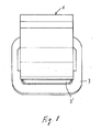
- FIG. 4 A further embodiment of the invention is schematically illustrated in figure 4.
- the yoke 1 is U-shaped and the cavity 2 defined thereby has three open sides.
- the yoke 1 has pole pieces 101'' and 201'' on the two opposite branches of the U shape, which form two coaxial pairs of opposite pole pieces.
- the relevant area for receiving the body or the part thereof to be examined is indicated as 102 and is made to substantially correspond to the magnetic gap T1 between the pole pieces 101'' on the closed side of the U-shaped yoke 1.
- the pole pieces 201'' of the other pair are disposed at the free ends of the two branches of the U-shaped yoke 1.
- the pole pieces 101'' and 201'' are arranged and dimensioned so as to define grooves for holding the coils 3, 3' therein and towards the parallel closed branch of the U-shaped yoke 1. Also, this embodiment provides two coils 3, 3', one surrounding both the pole pieces 101'', 201'' associated to a branch of the U-shaped yoke 1, and the other only surrounding the pole pieces 201'' at the free end of the branches of the U-shaped yoke 1.
- the inner pole pieces 101'' terminate at a shorter distance from each other with respect to those 201'' at the end of the branches of the U-shaped yoke 1, thus substantially forming a cavity which widens in the direction of the open transverse side of the U-shaped yoke 1.
- the magnetic field may be modified in the region of the magnetic gap T1, i.e. in the volume 102, for receiving the body or the part to be examined, in such a way as to compensate the deviation from the required field distribution characteristics in said region 102, and caused by the opening of the yoke 1 on one side parallel to the axis of the pole pieces 101'' and 201'', thus providing valid nuclear magnetic resonance images even when the electromagnetic structure is open.
- Such a configuration is very advantageous for detecting nuclear magnetic resonance images in the shoulder zone.
- the widening on the open side of the U-shaped yoke 1 allows to slip the magnetic structure onto the shoulder, accounting for the thickness increase in the thorax zone, and thus substantially following its morphology.
- the morphological adaptation is achieved while maintaining the quality of the detected images, and the reduction of the magnetic structure size and of the apparatus costs.
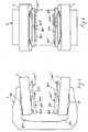
- FIG. 5 A more detailed and less schematic example of a magnetic structure whose configuration is substantially like the one according to fig. 4 is shown in figures 5 to 9.
- the magnetic structure according to those figures is identical to that of figure 4.
- the two examples differ for a few characteristics required to optimize the magnetic field characteristics in the volume or region 102 of the cavity 2.
- the yoke 1 has a variable section in the area 601 connected to the branches of the U shape. Moreover, said branches get increasingly thinner towards the free ends, both on the outer and on the inner sides.
- the pole pieces 101'' of the first pair have a passage aperture which divides them into two spaced parts, in the yoke closed side - to - open side direction.
- the passage aperture substantially extends from the basis of the pole pieces 101'', at the branches of the yoke 1 up to a common end plate.
- Said plate 701 widens on all sides, preferably in a flared way, partially superposing the coil 3.
- the plate 701 laterally narrows on both sides in the direction starting form the closed side of the U-shaped yoke 1, whereas, along the edge facing towards and parallel to said closed side of the U-shaped yoke 1, the plate 701 has a tooth 801, whose cross section is substantially shaped like a rectangular trapezium, which projects towards the opposite and coaxial pole piece 101''.
- the pole pieces 201'' at the ends of the two opposite branches of the U-shaped yoke 1 also terminate with a plate 901, flaringly widening both laterally and at the open side of the U-shaped yoke 1, and projecting out, beyond the ends of its branches, and partially superposing the coil 3' associated thereto.
- the extension of the pole pieces 201", projecting out at the open side of the yoke 1 narrows laterally, lake at the opposite side of the pole pieces 101''.
- the coils 3 surround both the pole pieces 101'' and the pole pieces 201'', together with the coil 3', associated thereto.
- At least one of the coils 3, 3' is oriented so as to be inclined, to such an extent that the two opposite coils 3, 3', having the same function and dimension, are divergently positioned towards the open side of the yoke 1.
- both coils 3 and coils 3' are inclined.
- the inclination may be either different or equal for the two coils 3, 3'.
- the invention is not restricted to the embodiments illustrated and described herein, but may be greatly varied, especially as regards construction.
- magnetic field coils instead of only providing magnetic field coils, the latter may be replaced by equivalent configurations of permanent magnets, or there may be provided, combinedly, both magnetic field coils and permanent magnets, appropriately arranged so as to obtain the desired characteristics of the magnetic field.
Landscapes
- Physics & Mathematics (AREA)
- Condensed Matter Physics & Semiconductors (AREA)
- General Physics & Mathematics (AREA)
- Magnetic Resonance Imaging Apparatus (AREA)
Claims (30)
- Structure magnétique pour générer des champs magnétiques destinés à être utilisés dans la détection d'images par résonance magnétique nucléaire, ayant des moyens (1, 101, 201, 301, 101', 201', 101", 201", 3, 3') pour générer un champ magnétique avec les caractéristiques nécessaires pour obtenir des images valides à l'intérieur d'une région tridimensionnelle prédéterminée (102), étant au moins une partie d'une cavité (2), qui est au moins partiellement contenue dans la structure magnétique, lesquels moyens pour générer le champ magnétique comprennent au moins une bobine (3, 3'), du type résistif ou supraconducteur et laquelle bobine (3, 3') est associée à un élément (1) constitué d'un matériau présentant une perméabilité élevée au flux magnétique, ce que l'on appelle la culasse, laquelle culasse définit ladite cavité (2), ayant au moins un côté ouvert, et une ou plusieurs pièces polaires (101, 201, 301 ; 101', 202' ; 101", 201") s'étendent à partir du côté intérieur faisant face à la cavité (2) de ladite culasse (1), au moins dans la région correspondant au volume (102) qui est destiné à recevoir le corps ou la partie de celui-ci destinée à être balayée, et se terminent par une extrémité libre à l'intérieur de la cavité (2), autour de laquelle la pièce polaire ou les pièces polaires, la bobine ou les bobines (3, 3') pour générer le flux magnétique sont disposées, ladite structure magnétique ayant au moins deux paires (101, 201, 301 ; 101', 202' ; 101", 201") de pièces polaires opposées et au moins une bobine (3, 3') pour chaque pièce polaire (101, 201, 301 ; 101', 202' ; 101", 201") desdites deux paires, caractérisée en ce que
la culasse (1) peut être étendue pour obtenir une nouvelle taille par rapport à sa branche parallèle à l'axe des pièces polaires (101', 102') et/ou aux branches transversales audit axe. - Structure magnétique selon la revendication 1, caractérisée en ce que des moyens informatiques sont prévus, ayant en mémoire un programme de calcul pour l'ajustement des courants circulant dans les bobines (3, 3') pour l'exécution automatique des corrections pour adapter la structure magnétique à la nouvelle taille de la culasse (1).
- Structure magnétique selon les revendications 1 ou 2, caractérisée en ce qu'elle comprend un ensemble d'éléments modulaires qui peuvent être assemblés et désassemblés pour adapter dimensionnellement la structure magnétique à la nouvelle taille de la culasse (1).
- Structure magnétique selon une ou plusieurs des revendications précédentes, caractérisée en ce qu'au moins une des deux paires de pièces polaires (101, 101', 101") délimite sur les côtés opposés le volume (102), à l'intérieur de la cavité (2), étant destiné à recevoir le corps ou la partie examinée.
- Structure magnétique selon une ou plusieurs des revendications précédentes, caractérisée en ce qu'elle comprend au moins trois côtés ouverts, dans laquelle ladite paire de pièces polaires (101, 101', 101") qui délimite sur les côtés opposés le volume (102), à l'intérieur de la cavité (2), étant destiné à recevoir le corps ou la partie de celui-ci destinée à être examinée, est une desdites paires de pièces polaires avec la distance la plus grande du côté ouvert où ledit corps est introduit dans ladite cavité (2).
- Structure magnétique selon une ou plusieurs des revendications précédentes, caractérisée en ce que les pièces polaires (101, 201, 301 ; 101', 202' ; 101", 201") de chacune des paires sont coaxiales les unes par rapport aux autres.
- Structure magnétique selon une ou plusieurs des revendications précédentes, caractérisée en ce que les deux pièces polaires opposées (101, 201, 301 ; 101', 202' ; 101", 201") des paires de pièces polaires, sont entourées d'au moins une bobine de champ commune (3), alors que pour chaque pièce polaire (101, 201, 301 ; 101', 202' ; 101", 201") ou uniquement pour une des pièces polaires il est prévu une bobine séparée supplémentaire entourant uniquement ladite pièce polaire.
- Structure magnétique selon une ou plusieurs des revendications précédentes, caractérisée en ce que les paires de pièces polaires (101, 201, 301 ; 101', 202' ; 101", 201") sont de préférence disposées symétriquement les unes par rapport aux autres par rapport à un plan médian coupant perpendiculairement les côtés ouverts de la cavité (2).
- Structure magnétique selon une ou plusieurs des revendications précédentes, caractérisée en ce que la culasse (1) et la cavité (2) présentent une forme symétrique, par rapport à au moins un axe médian coupant perpendiculairement un des côtés ouverts de la cavité (2).
- Structure magnétique selon une ou plusieurs des revendications précédentes, caractérisée en ce que les pièces polaires (101, 201, 301 ; 101', 202' ; 101", 201") des paires adjacentes sont espacées de manière à former des gorges pour loger les bobines (3, 3') lesdites gorges étant situées dans une position intermédiaire entre lesdites pièces polaires.
- Structure magnétique selon une ou plusieurs des revendications précédentes, caractérisée en ce que chaque pièce polaire comporte sur au moins un côté et sur son extrémité faisant face à la cavité (2) un flasque périphérique (401'), chevauchant, au moins partiellement, peut être complètement, le côté de la bobine (3, 3') faisant face à l'intérieur de la cavité (2), c'est-à-dire l'extrémité des pièces polaires (101', 201' ; 101", 201").
- Structure magnétique selon une ou plusieurs des revendications précédentes, caractérisée en ce que les pièces polaires (101") de chaque paire présentent des ouvertures de passage ou des entrefers (601), ayant une certaine longueur de manière à les diviser au moins dans la région médiane, et deux parties espacées.
- Structure magnétique selon une ou plusieurs des revendications précédentes, caractérisée en ce que les surfaces opposées des paires de pièces polaires (101, 201, 301 ; 101', 202' ; 101", 201") sont parallèles les unes par rapport aux autres.
- Structure magnétique selon une ou plusieurs des revendications 1 à 10, caractérisée en ce que les surfaces opposées des paires de pièces polaires (101, 201, 301 ; 101', 202' ; 101", 201") sont orientées de manière à diverger ou converger les unes par rapport aux autres.
- Structure magnétique selon une ou plusieurs des revendications précédentes, caractérisée en ce que les surfaces opposées des paires de pièces polaires (101, 201, 301 ; 101', 202' ; 101", 201") présentent une forme avec des profils identiques prédéterminés (701), complémentaires les uns par rapport aux autres ou différents les uns des autres.
- Structure magnétique selon une ou plusieurs des revendications précédentes, caractérisée en ce que les pièces polaires (101") d'au moins une desdites paires de pièces polaires comportent sur un bord de leur extrémité faisant face à la cavité (2) une dent (801), qui fait saillie vers la pièce polaire opposée de ladite paire de pièces polaires.
- Structure magnétique selon une ou plusieurs des revendications précédentes, caractérisée en ce que les bobines (3, 3') associées aux pièces polaires opposées (101", 201") des paires différentes sont orientées avec leurs axes parallèles et coïncidants les uns avec les autres.
- Structure magnétique selon une ou plusieurs des revendications précédentes, caractérisée en ce que les bobines (3, 3') associées aux pièces polaires opposées (101", 201") des paires différentes sont orientées avec leurs axes inclinés l'un par rapport à l'autre à un tel point que les bobines (3, 3') prennent des positions divergentes ou convergentes les unes par rapport aux autres et avec des inclinaisons identiques ou différentes pour des paires de bobines (3, 3') ayant des fonctions égales ou pour toutes les bobines (3, 3').
- Structure magnétique selon une ou plusieurs des revendications précédentes, caractérisée en ce qu'elle comprend des éléments magnétiques permanents, combinés aux bobines (3, 3') ou qui les remplacent complètement.
- Structure magnétique selon une ou plusieurs des revendications précédentes, caractérisée en ce que la culasse (1) présente une forme fermée annulaire, la cavité (2) étant uniquement ouverte sur deux côtés opposés.
- Structure magnétique selon une ou plusieurs des revendications précédentes 1 à 20, caractérisée en ce que la culasse (1) présente une forme ouverte annulaire, qui est une forme en C ou en U.
- Structure magnétique selon une ou plusieurs des revendications précédentes, caractérisée en ce que la culasse (1) est un élément de connexion entre des moyens pour définir une cavité (2), c'est-à-dire un volume prédéterminé (102), lesquels moyens définissent uniquement la cavité (2) sur deux côtés opposés, et comprennent les extrémités des paires de pièces polaires opposées (101', 201').
- Structure magnétique selon la revendication 22, caractérisée en ce que les différentes paires de pièces polaires (101', 201') sont disposées concentriquement, les pièces polaires extérieures ayant des formes annulaires, de préférence les paires de pièces polaires (101', 201') ayant des formes circulaires.
- Structure magnétique selon une ou plusieurs des revendications 21 ou 22, caractérisée en ce que la culasse (1) présente une forme en C ou en U, ayant un côté fermé délimitant la cavité (2) qui est situé à l'opposé d'un côté ouvert de la cavité (2), les différentes paires de pièces polaires (101", 201") étant disposées côte à côte dans la direction partant d'un des côtés fermés vers un côté ouvert opposé de la culasse (1).
- Structure magnétique selon la revendication 24, caractérisée en ce qu'elle comprend deux paires de pièces polaires opposées (101", 201"), ayant des longueurs différentes, et définissant entre chaque paire de pièces polaires opposées des entrefers (T1, T2) de taille différente, une paire de pièces polaires opposées (201") est disposée plus près d'un côté ouvert de la culasse ayant une forme en U (1) et est plus courte que la paire adjacente de pièces polaires opposées (101"), qui est plus proche du côté fermé opposé de la culasse (1), alors que la région (102) destinée à recevoir la partie concernée pour l'examen du corps ou la partie de celle-ci, correspond à l'entrefer (T1), entre les deux pièces polaires (101"), plus proche du côté fermé de la culasse (1).
- Structure magnétique selon la revendication 25, caractérisée en ce que les côtés opposés des pièces polaires (101") plus proches du côté fermé de la culasse (1) sont essentiellement plans, et le long du bord disposé face audit côté fermé, présentent une extension (701) vers l'intérieur de la cavité (2), sous la forme d'une dent avec une section ayant de préférence la forme d'un trapèze rectangle.
- Structure magnétique selon une ou plusieurs des revendications précédentes, caractérisée en ce que les pièces polaires (201") s'étendent avec un bord faisant saillie au-delà des extrémités des branches opposées de la culasse de forme en U (1), ledit bord s'effile latéralement vers son extrémité en saillie, chevauchant partiellement la bobine (3').
- Structure magnétique selon une ou plusieurs des revendications précédentes, caractérisée en ce que les pièces polaires (101") d'une paire de pièces polaires sont respectivement associées à une bobine (3), qui entoure la pièce polaire correspondante de ladite paire de pièces polaires (101") et l'autre pièce polaire adjacente (201") de la seconde paire de pièces polaires (201''), et à une bobine (3'), entourant uniquement ladite pièce polaire supplémentaire (201") de la seconde paire des pièces polaires.
- Structure magnétique selon une ou plusieurs des revendications précédentes, caractérisée en ce que les bobines (3) et/ou les bobines (3') sont inclinées de manière divergente dans la direction du côté fermé vers le côté ouvert de la culasse de forme en U (1).
- Machine pour détecter des images par résonance magnétique nucléaire, caractérisée en ce qu'elle est conçue pour détecter des images dans la zone de l'épaule et en ce qu'elle présente une construction selon une ou plusieurs des revendications précédentes 1 à 29.
Applications Claiming Priority (2)
| Application Number | Priority Date | Filing Date | Title |
|---|---|---|---|
| IT97SV000024A IT1294051B1 (it) | 1997-04-29 | 1997-04-29 | Struttura magnetica per la generazione di campi magnetici adatti all'uso nel rilevamento d'immagine in risonanza magnetica nucleare |
| ITSV970024 | 1997-04-29 |
Publications (3)
| Publication Number | Publication Date |
|---|---|
| EP0875768A2 EP0875768A2 (fr) | 1998-11-04 |
| EP0875768A3 EP0875768A3 (fr) | 2000-03-22 |
| EP0875768B1 true EP0875768B1 (fr) | 2006-11-02 |
Family
ID=11408221
Family Applications (1)
| Application Number | Title | Priority Date | Filing Date |
|---|---|---|---|
| EP98107116A Expired - Lifetime EP0875768B1 (fr) | 1997-04-29 | 1998-04-20 | Structure magnétique pour un appareil d'imagerie par résonance magnétique nucléaire |
Country Status (5)
| Country | Link |
|---|---|
| US (1) | US6130538A (fr) |
| EP (1) | EP0875768B1 (fr) |
| DE (1) | DE69836293T2 (fr) |
| ES (1) | ES2275291T3 (fr) |
| IT (1) | IT1294051B1 (fr) |
Cited By (1)
| Publication number | Priority date | Publication date | Assignee | Title |
|---|---|---|---|---|
| US20090310841A1 (en) * | 2006-06-06 | 2009-12-17 | Esaote S.P.A. | Apparatus for magnetic resonance imaging of patients with limbs, particularly lower limbs, under natural stress |
Families Citing this family (14)
| Publication number | Priority date | Publication date | Assignee | Title |
|---|---|---|---|---|
| JP2774777B2 (ja) * | 1994-11-25 | 1998-07-09 | 株式会社日立メディコ | 磁気共鳴イメ−ジング装置 |
| IT1294051B1 (it) * | 1997-04-29 | 1999-03-15 | Esaote Spa | Struttura magnetica per la generazione di campi magnetici adatti all'uso nel rilevamento d'immagine in risonanza magnetica nucleare |
| US5994991A (en) * | 1998-02-19 | 1999-11-30 | General Electric Company | Open magnet having shielding |
| US6504461B2 (en) | 2001-03-26 | 2003-01-07 | General Electric Company | Open magnet with recessed field shaping coils |
| US6662434B2 (en) | 2001-04-03 | 2003-12-16 | General Electric Company | Method and apparatus for magnetizing a permanent magnet |
| US6518867B2 (en) | 2001-04-03 | 2003-02-11 | General Electric Company | Permanent magnet assembly and method of making thereof |
| DE10117595C1 (de) * | 2001-04-07 | 2002-12-05 | Bruker Biospin Gmbh | Asymmetrische Anordnung permanentmagnetischer Elemente für eine Magnetresonanzapparatur und Verfahren zur Herstellung einer solchen Magnetanordnung |
| US6678189B2 (en) * | 2002-02-25 | 2004-01-13 | Hewlett-Packard Development Company, L.P. | Method and system for performing equipotential sensing across a memory array to eliminate leakage currents |
| US6954070B2 (en) * | 2003-01-06 | 2005-10-11 | Brk Wireless Company, Inc. | NMR imaging system with conical permanent magnet |
| CN100556359C (zh) * | 2003-02-10 | 2009-11-04 | 日立金属株式会社 | 磁场产生装置 |
| US6831463B1 (en) * | 2003-06-20 | 2004-12-14 | Brigham And Women's Hospital | Ferrorefraction MRI system having two orthogonal remote field polarization axes |
| US7148689B2 (en) | 2003-09-29 | 2006-12-12 | General Electric Company | Permanent magnet assembly with movable permanent body for main magnetic field adjustable |
| US7423431B2 (en) * | 2003-09-29 | 2008-09-09 | General Electric Company | Multiple ring polefaceless permanent magnet and method of making |
| IT1397713B1 (it) | 2010-01-22 | 2013-01-24 | Esaote Spa | Macchina per risonanza magnetica nucleare con mezzi per la correzione dell'omogeneità del campo magnetico. |
Family Cites Families (6)
| Publication number | Priority date | Publication date | Assignee | Title |
|---|---|---|---|---|
| US5138326A (en) * | 1988-10-14 | 1992-08-11 | Oxford Medical Limited | Magnetic field generating assembly and method |
| JPH06197715A (ja) * | 1992-03-16 | 1994-07-19 | Kissei Pharmaceut Co Ltd | たんぱく質調整そば |
| JP3742662B2 (ja) * | 1992-08-05 | 2006-02-08 | ゼネラル・エレクトリック・カンパニイ | 開放形磁気共鳴イメージングに適した磁石 |
| US5378988A (en) * | 1993-01-22 | 1995-01-03 | Pulyer; Yuly M. | MRI system having high field strength open access magnet |
| JP3113513B2 (ja) * | 1994-07-29 | 2000-12-04 | 住友特殊金属株式会社 | Mri用磁界発生装置 |
| IT1294051B1 (it) * | 1997-04-29 | 1999-03-15 | Esaote Spa | Struttura magnetica per la generazione di campi magnetici adatti all'uso nel rilevamento d'immagine in risonanza magnetica nucleare |
-
1997
- 1997-04-29 IT IT97SV000024A patent/IT1294051B1/it active IP Right Grant
-
1998
- 1998-04-20 EP EP98107116A patent/EP0875768B1/fr not_active Expired - Lifetime
- 1998-04-20 ES ES98107116T patent/ES2275291T3/es not_active Expired - Lifetime
- 1998-04-20 US US09/062,777 patent/US6130538A/en not_active Expired - Lifetime
- 1998-04-20 DE DE69836293T patent/DE69836293T2/de not_active Expired - Lifetime
Cited By (2)
| Publication number | Priority date | Publication date | Assignee | Title |
|---|---|---|---|---|
| US20090310841A1 (en) * | 2006-06-06 | 2009-12-17 | Esaote S.P.A. | Apparatus for magnetic resonance imaging of patients with limbs, particularly lower limbs, under natural stress |
| US8126245B2 (en) | 2006-06-06 | 2012-02-28 | Esaote, S.P.A. | Apparatus for magnetic resonance imaging of patients with limbs, particularly lower limbs, under natural stress |
Also Published As
| Publication number | Publication date |
|---|---|
| ITSV970024A1 (it) | 1998-10-29 |
| US6130538A (en) | 2000-10-10 |
| IT1294051B1 (it) | 1999-03-15 |
| DE69836293D1 (de) | 2006-12-14 |
| EP0875768A2 (fr) | 1998-11-04 |
| ES2275291T3 (es) | 2007-06-01 |
| DE69836293T2 (de) | 2007-05-31 |
| ITSV970024A0 (it) | 1997-04-29 |
| EP0875768A3 (fr) | 2000-03-22 |
Similar Documents
| Publication | Publication Date | Title |
|---|---|---|
| EP0875768B1 (fr) | Structure magnétique pour un appareil d'imagerie par résonance magnétique nucléaire | |
| US6014070A (en) | Ferromagnetic yoke magnets for medical magnetic resonance studies | |
| EP0985934B1 (fr) | Circuit magnétique avec aimants permanents montés en opposition | |
| JP3742662B2 (ja) | 開放形磁気共鳴イメージングに適した磁石 | |
| EP0770881B1 (fr) | Aimant d'IRM blindé et ouvert | |
| CA1180374A (fr) | Electro-aimant utilise en resonance magnetique nucleaire | |
| US5570073A (en) | NMR slice coil | |
| JP3694659B2 (ja) | マグネット及びその磁場調整方法並びに磁気共鳴撮像装置 | |
| JP3731231B2 (ja) | 超電導磁石装置 | |
| US7071694B1 (en) | Magnet assembly of an MRI system with concentric annular ferromagnetic laminations | |
| EP0817211B1 (fr) | Dispositif magnetique supraconducteur et dispositif d'imagerie rmn l'utilisant | |
| US5574417A (en) | Open MRI magnet with homogeneous imaging volume | |
| US6154110A (en) | Gradient magnetic field coil and magnetic resonance imaging apparatus using the same | |
| EP0770883B1 (fr) | Aimant d'IRM ouvert à refroidissement par fluide cryogénique avec champ magnétique uniforme | |
| EP0982598B1 (fr) | Système de résonance magnétique comportant des anneaux de compensation | |
| WO1988004057A1 (fr) | Scanners a resonance magnetique nucleaire | |
| EP0940684B1 (fr) | Système magnétique supraconducteur | |
| US5992006A (en) | Method for passive control of magnet hemogeneity | |
| US6975117B1 (en) | Method and apparatus for magnetic resonance imaging | |
| US4758812A (en) | Frame structure for a magnet system for nuclear spin tomography | |
| EP0695950B1 (fr) | Assemblages de bobines de gradients pour appareil d'imagerie par résonance magnétique | |
| GB2315127A (en) | Open-access MRI magnet with improved homogeneity | |
| US6504461B2 (en) | Open magnet with recessed field shaping coils | |
| US5864235A (en) | Nuclear magnetic resonance tomography apparatus with a combined radio-frequency antenna and gradient coil structure | |
| EP3615953B1 (fr) | Système de réduction d'un champ de franges magnétiques d'un dispositif d'imagerie par résonance magnétique |
Legal Events
| Date | Code | Title | Description |
|---|---|---|---|
| PUAI | Public reference made under article 153(3) epc to a published international application that has entered the european phase |
Free format text: ORIGINAL CODE: 0009012 |
|
| AK | Designated contracting states |
Kind code of ref document: A2 Designated state(s): DE ES FR GB IT |
|
| AX | Request for extension of the european patent |
Free format text: AL;LT;LV;MK;RO;SI |
|
| PUAL | Search report despatched |
Free format text: ORIGINAL CODE: 0009013 |
|
| AK | Designated contracting states |
Kind code of ref document: A3 Designated state(s): AT BE CH CY DE DK ES FI FR GB GR IE IT LI LU MC NL PT SE |
|
| AX | Request for extension of the european patent |
Free format text: AL;LT;LV;MK;RO;SI |
|
| RIC1 | Information provided on ipc code assigned before grant |
Free format text: 7G 01R 33/38 A |
|
| 17P | Request for examination filed |
Effective date: 20000907 |
|
| AKX | Designation fees paid |
Free format text: DE ES FR GB IT |
|
| 17Q | First examination report despatched |
Effective date: 20050504 |
|
| RAP1 | Party data changed (applicant data changed or rights of an application transferred) |
Owner name: ESAOTE S.P.A. |
|
| RAP1 | Party data changed (applicant data changed or rights of an application transferred) |
Owner name: ESAOTE S.P.A. |
|
| GRAP | Despatch of communication of intention to grant a patent |
Free format text: ORIGINAL CODE: EPIDOSNIGR1 |
|
| RAP1 | Party data changed (applicant data changed or rights of an application transferred) |
Owner name: ESAOTE S.P.A. |
|
| GRAS | Grant fee paid |
Free format text: ORIGINAL CODE: EPIDOSNIGR3 |
|
| GRAA | (expected) grant |
Free format text: ORIGINAL CODE: 0009210 |
|
| AK | Designated contracting states |
Kind code of ref document: B1 Designated state(s): DE ES FR GB IT |
|
| PG25 | Lapsed in a contracting state [announced via postgrant information from national office to epo] |
Ref country code: IT Free format text: LAPSE BECAUSE OF FAILURE TO SUBMIT A TRANSLATION OF THE DESCRIPTION OR TO PAY THE FEE WITHIN THE PRESCRIBED TIME-LIMIT;WARNING: LAPSES OF ITALIAN PATENTS WITH EFFECTIVE DATE BEFORE 2007 MAY HAVE OCCURRED AT ANY TIME BEFORE 2007. THE CORRECT EFFECTIVE DATE MAY BE DIFFERENT FROM THE ONE RECORDED. Effective date: 20061102 |
|
| REG | Reference to a national code |
Ref country code: GB Ref legal event code: FG4D |
|
| REF | Corresponds to: |
Ref document number: 69836293 Country of ref document: DE Date of ref document: 20061214 Kind code of ref document: P |
|
| ET | Fr: translation filed | ||
| REG | Reference to a national code |
Ref country code: ES Ref legal event code: FG2A Ref document number: 2275291 Country of ref document: ES Kind code of ref document: T3 |
|
| PLBE | No opposition filed within time limit |
Free format text: ORIGINAL CODE: 0009261 |
|
| STAA | Information on the status of an ep patent application or granted ep patent |
Free format text: STATUS: NO OPPOSITION FILED WITHIN TIME LIMIT |
|
| 26N | No opposition filed |
Effective date: 20070803 |
|
| PGFP | Annual fee paid to national office [announced via postgrant information from national office to epo] |
Ref country code: FR Payment date: 20100519 Year of fee payment: 13 Ref country code: ES Payment date: 20100528 Year of fee payment: 13 |
|
| PGFP | Annual fee paid to national office [announced via postgrant information from national office to epo] |
Ref country code: GB Payment date: 20100408 Year of fee payment: 13 |
|
| GBPC | Gb: european patent ceased through non-payment of renewal fee |
Effective date: 20110420 |
|
| REG | Reference to a national code |
Ref country code: FR Ref legal event code: ST Effective date: 20111230 |
|
| PG25 | Lapsed in a contracting state [announced via postgrant information from national office to epo] |
Ref country code: FR Free format text: LAPSE BECAUSE OF NON-PAYMENT OF DUE FEES Effective date: 20110502 |
|
| PG25 | Lapsed in a contracting state [announced via postgrant information from national office to epo] |
Ref country code: GB Free format text: LAPSE BECAUSE OF NON-PAYMENT OF DUE FEES Effective date: 20110420 |
|
| REG | Reference to a national code |
Ref country code: ES Ref legal event code: FD2A Effective date: 20120604 |
|
| PG25 | Lapsed in a contracting state [announced via postgrant information from national office to epo] |
Ref country code: ES Free format text: LAPSE BECAUSE OF NON-PAYMENT OF DUE FEES Effective date: 20110421 |
|
| PGFP | Annual fee paid to national office [announced via postgrant information from national office to epo] |
Ref country code: DE Payment date: 20120430 Year of fee payment: 15 |
|
| PG25 | Lapsed in a contracting state [announced via postgrant information from national office to epo] |
Ref country code: DE Free format text: LAPSE BECAUSE OF NON-PAYMENT OF DUE FEES Effective date: 20131101 |
|
| REG | Reference to a national code |
Ref country code: DE Ref legal event code: R119 Ref document number: 69836293 Country of ref document: DE Effective date: 20131101 |
|
| PGFP | Annual fee paid to national office [announced via postgrant information from national office to epo] |
Ref country code: IT Payment date: 20170426 Year of fee payment: 20 |